2005 SUZUKI JIMNY bolts
[x] Cancel search: boltsPage 29 of 687

Downloaded from www.Manualslib.com manuals search engine 0A-24 GENERAL INFORMATION
Fasteners Information
Metric Fasteners
Most of the fasteners used for this vehicle are metric fasteners. When replacing any fasteners, it is most impor-
tant that replacement fasteners be the correct diameter, thread pitch and strength.
Fastener Strength Identification
Most commonly used metric fastener strength property classes are 4T, 6.8, 7T, 8.8 and radial line with the class
identification embossed on the head of each bolt. Some metric nuts will be marked with punch, 6 or 8 mark
strength identification on the nut face. Figure shows the different strength markings.
When replacing metric fasteners, be careful to use bolts and nuts of the same strength or greater than the origi-
nal fasteners (the same number marking or higher). It is likewise important to select replacement fasteners of
the correct diameter and thread pitch. Correct replacement bolts and nuts are available through the parts divi-
sion.
Metric bolts: Identification class numbers or marks correspond to bolt strength (increasing numbers represent
increasing strength).
Standard Tightening Torque
Each fastener should be tightened to the torque specified in each section of this manual. If no description or
specification is provided, refer to the following tightening torque chart for the applicable torque for each fastener.
When a fastener of greater strength than the original one is used, however, use the torque specified for the orig-
inal fastener.
1. Nuts strength identification
NOTE:
For the flanged bolt, flanged nut and self-lock nut of 4T and 7T strength, add 10% to the tightening
torque given in the chart below.
The chart below is applicable only where the fastened parts are made of steel light alloy.
Page 35 of 687

Downloaded from www.Manualslib.com manuals search engine 0B-4 MAINTENANCE AND LUBRICATION
Maintenance Recommended Under Severe Driving Conditions
If the vehicle is usually used under the conditions corresponding to any severe condition code given below, it is
recommended that applicable maintenance operation be performed at the particular interval as shown in the fol-
lowing table.
Severe condition code
A : Repeated short trips
B : Driving on rough and/or muddy roads
C : Driving on dusty roads
D : Driving in extremely cold weather and/or salted roads
E : Repeated short trips in extremely cold weather
F : Leaded fuel use
G : – – – – –
H : Trailer towing (if admitted)
Severe
Condition CodeMaintenanceMaintenance
OperationMaintenance Interval
– B C D – – – –Drive belt (V-rib belt)IEvery 15,000 km
(9,000 miles) or 12 months
REvery 45,000 km
(27,000 miles) or 36 months
A – C D E F – H Engine oil and oil filter R Every 5,000 km (3,000 miles) or 4 months
– B – – – – – –Exhaust pipe mountings IEvery 15,000 km
(9,000 miles) or 12 months
– – C – – – – –Air cleaner filter ✱1I Every 2,500 km (1,500 miles)
REvery 30,000 km
(18,000 miles) or 24 months
A B C – E F – H Spark plugsNickel spark plug R Every 10,000 km (6,000 miles) or 8 months
Iridium spark plug
REvery 30,000 km
(18,000 miles) or 24 months
– B C D – – – H Wheel bearing IEvery 15,000 km
(9,000 miles) or 12 months
– B – – – – – –Suspension bolts and nuts TEvery 15,000 km
(9,000 miles) or 12 months
– B – D E – – H Propeller shafts IEvery 15,000 km
(9,000 miles) or 12 months
– B – – E – – HManual transmission,
transfer and differential oilRFirst time only:
15,000 km (9,000 miles) or 12 months
Second time and after: Every 30,000 km
(18,000 miles) or 24 months reckoning from
0 km (0 mile) or 0 month
– B – – E – – H Automatic transmission fluid REvery 30,000 km
(18,000 miles) or 24 months
– B C D – – – –Steering knuckle seal IEvery 15,000 km
(9,000 miles) or 12 months
NOTE:
“I”: Inspect and correct, replace or lubricate if necessary
“R”: Replace or change
“T”: Tighten to the specified torque
✱
✱✱ ✱1: Inspect or replace more frequently if necessary
Page 36 of 687
Downloaded from www.Manualslib.com manuals search engine MAINTENANCE AND LUBRICATION 0B-5
Maintenance Service
Engine
Drive Belt
WATER PUMP AND GENERATOR DRIVE BELT INSPEC-
TION
1) Disconnect negative cable at battery.
2) Inspect belt for cracks, cuts, deformation, wear and cleanli-
ness. If any defect exists, replace.
Check belt for tension.
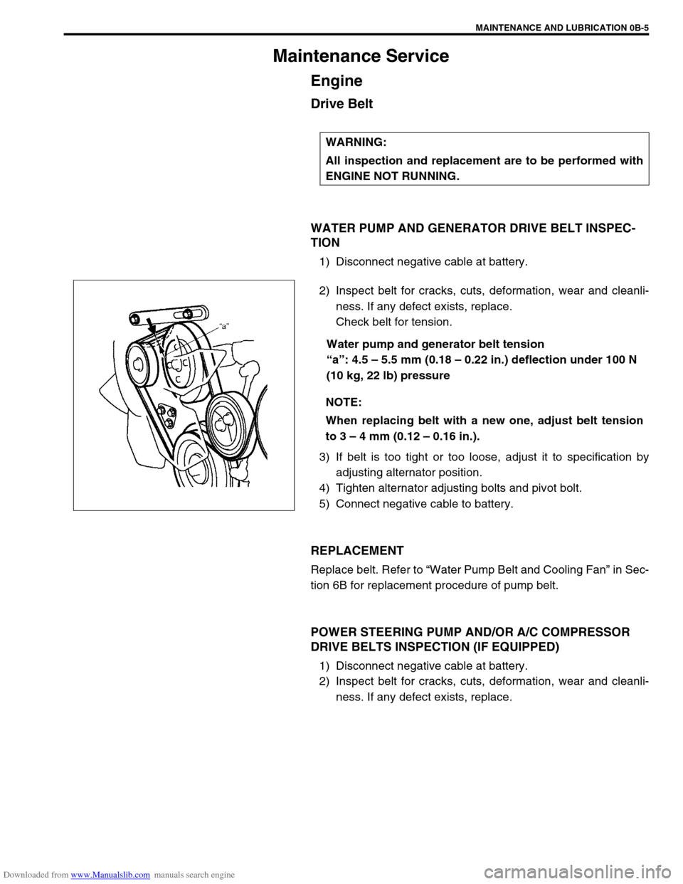
Water pump and generator belt tension
“a”: 4.5 – 5.5 mm (0.18 – 0.22 in.) deflection under 100 N
(10 kg, 22 lb) pressure
3) If belt is too tight or too loose, adjust it to specification by
adjusting alternator position.
4) Tighten alternator adjusting bolts and pivot bolt.
5) Connect negative cable to battery.
REPLACEMENT
Replace belt. Refer to “Water Pump Belt and Cooling Fan” in Sec-
tion 6B for replacement procedure of pump belt.
POWER STEERING PUMP AND/OR A/C COMPRESSOR
DRIVE BELTS INSPECTION (IF EQUIPPED)
1) Disconnect negative cable at battery.
2) Inspect belt for cracks, cuts, deformation, wear and cleanli-
ness. If any defect exists, replace. WARNING:
All inspection and replacement are to be performed with
ENGINE NOT RUNNING.
NOTE:
When replacing belt with a new one, adjust belt tension
to 3 – 4 mm (0.12 – 0.16 in.).
Page 40 of 687

Downloaded from www.Manualslib.com manuals search engine MAINTENANCE AND LUBRICATION 0B-9
When carrying out periodic maintenance, or the vehicle is raised
for other service, check exhaust system as follows:
Check rubber mountings for damage, deterioration, and out
of position.
Check exhaust system for leakage, loose connections, dents
and damages.
If bolts or nuts are loose, tighten them to specification.
Check nearby body areas for damaged, missing, or misposi-
tioned parts, open seams, holes, loose connections or other
defects which could permit exhaust fumes to seep into the
vehicle.
Make sure that exhaust system components have enough
clearance from the underbody to avoid overheating and pos-
sible damage to the floor carpet.
Any defects should be fixed at once.
Ignition System
Spark Plugs
REPLACEMENT
Replace spark plugs with new ones referring to “Spark Plug” in
Section 6F.
Fuel System
Air Cleaner Filter
INSPECTION
1) Remove air cleaner case clamps (1).
2) Take cleaner filter out of air cleaner case.
3) Check air cleaner filter for dirt. Replace excessively dirty fil-
ter.
4) Blow off dust by compressed air from air outlet side of filter.
5) Install air cleaner filter into case.
6) Install air cleaner case cap and clamp it securely.
Page 41 of 687
Downloaded from www.Manualslib.com manuals search engine 0B-10 MAINTENANCE AND LUBRICATION
REPLACEMENT
Replace air cleaner filter with new one according to steps 1), 2)
and 5), 6) of inspection procedure.
Fuel Lines and Connections
INSPECTION
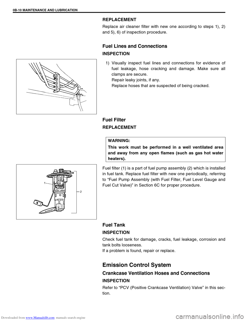
1) Visually inspect fuel lines and connections for evidence of
fuel leakage, hose cracking and damage. Make sure all
clamps are secure.
Repair leaky joints, if any.
Replace hoses that are suspected of being cracked.
Fuel Filter
REPLACEMENT
Fuel filter (1) is a part of fuel pump assembly (2) which is installed
in fuel tank. Replace fuel filter with new one periodically, referring
to “Fuel Pump Assembly (with Fuel Filter, Fuel Level Gauge and
Fuel Cut Valve)” in Section 6C for proper procedure.
Fuel Tank
INSPECTION
Check fuel tank for damage, cracks, fuel leakage, corrosion and
tank bolts looseness.
If a problem is found, repair or replace.
Emission Control System
Crankcase Ventilation Hoses and Connections
INSPECTION
Refer to “PCV (Positive Crankcase Ventilation) Valve” in this sec-
tion.
WARNING:
This work must be performed in a well ventilated area
and away from any open flames (such as gas hot water
heaters).
Page 42 of 687
Downloaded from www.Manualslib.com manuals search engine MAINTENANCE AND LUBRICATION 0B-11
PCV (Positive Crankcase Ventilation) Valve
INSPECTION
Check crankcase ventilation hose and PCV hose for leaks, cracks
or clog, and PCV valve for stick or clog. Refer to “PCV System” of
Section 6E for PCV valve checking procedure.
Fuel Evaporative Emission Control System
INSPECTION
1) Visually inspect hoses for cracks, damage, or excessive
bends. Inspect all clamps for damage and proper position.
2) Check EVAP canister for operation and clog, referring to
“Evaporative Emission (EVAP) Control System” in Section
6E.
If a malfunction is found, repair or replace.
Chassis and Body
Clutch
INSPECTION
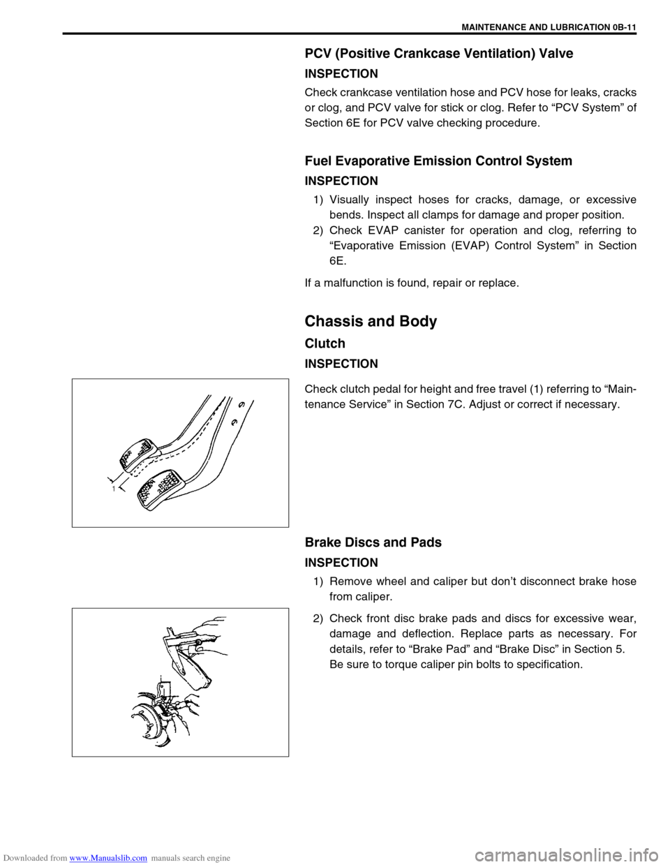
Check clutch pedal for height and free travel (1) referring to “Main-
tenance Service” in Section 7C. Adjust or correct if necessary.
Brake Discs and Pads
INSPECTION
1) Remove wheel and caliper but don’t disconnect brake hose
from caliper.
2) Check front disc brake pads and discs for excessive wear,
damage and deflection. Replace parts as necessary. For
details, refer to “Brake Pad” and “Brake Disc” in Section 5.
Be sure to torque caliper pin bolts to specification.
Page 45 of 687
Downloaded from www.Manualslib.com manuals search engine 0B-14 MAINTENANCE AND LUBRICATION
3) Rotate tires.
For details, refer to “Tire Rotation” in Section 3F.
WHEEL DISCS INSPECTION
Inspect each wheel disc for dents, distortion and cracks. A disc in
badly damaged condition must be replaced.
WHEEL BEARING INSPECTION
1) Check front wheel bearing for wear, damage, abnormal
noise or rattles. For details, refer to “Wheel Disc, Nut and
Bearing Check” in Section 3D.
2) Check rear wheel bearing for wear, damage, abnormal noise
or rattles. For details, refer to “Wheel Disc, Nut and Bearing
Check” in Section 3E.
Suspension System
INSPECTION
Check suspension bolts and nuts for tightness and retighten them
as necessary.
Repair or replace defective parts, if any.
FRONT
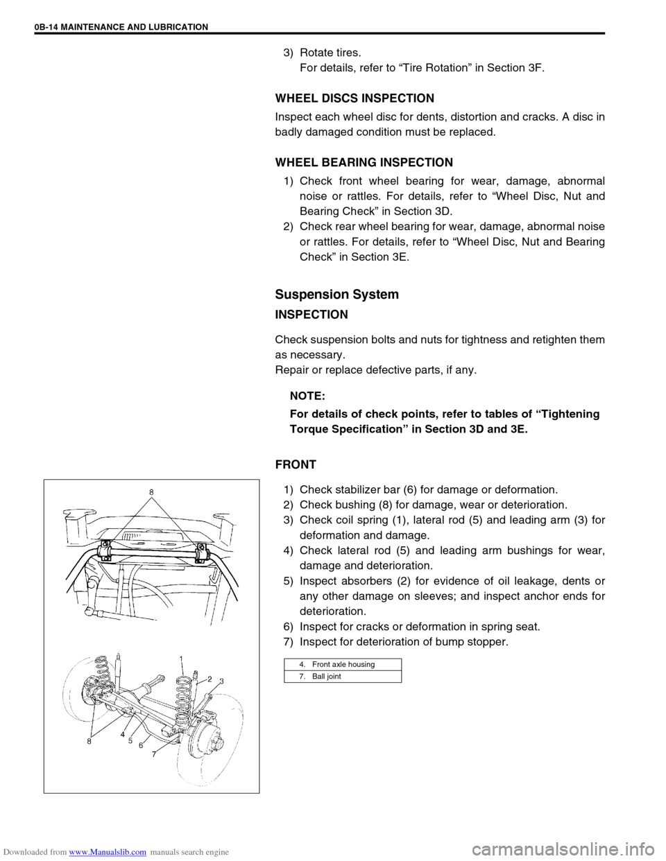
1) Check stabilizer bar (6) for damage or deformation.
2) Check bushing (8) for damage, wear or deterioration.
3) Check coil spring (1), lateral rod (5) and leading arm (3) for
deformation and damage.
4) Check lateral rod (5) and leading arm bushings for wear,
damage and deterioration.
5) Inspect absorbers (2) for evidence of oil leakage, dents or
any other damage on sleeves; and inspect anchor ends for
deterioration.
6) Inspect for cracks or deformation in spring seat.
7) Inspect for deterioration of bump stopper.NOTE:
For details of check points, refer to tables of “Tightening
Torque Specification” in Section 3D and 3E.
4. Front axle housing
7. Ball joint
Page 46 of 687
Downloaded from www.Manualslib.com manuals search engine MAINTENANCE AND LUBRICATION 0B-15
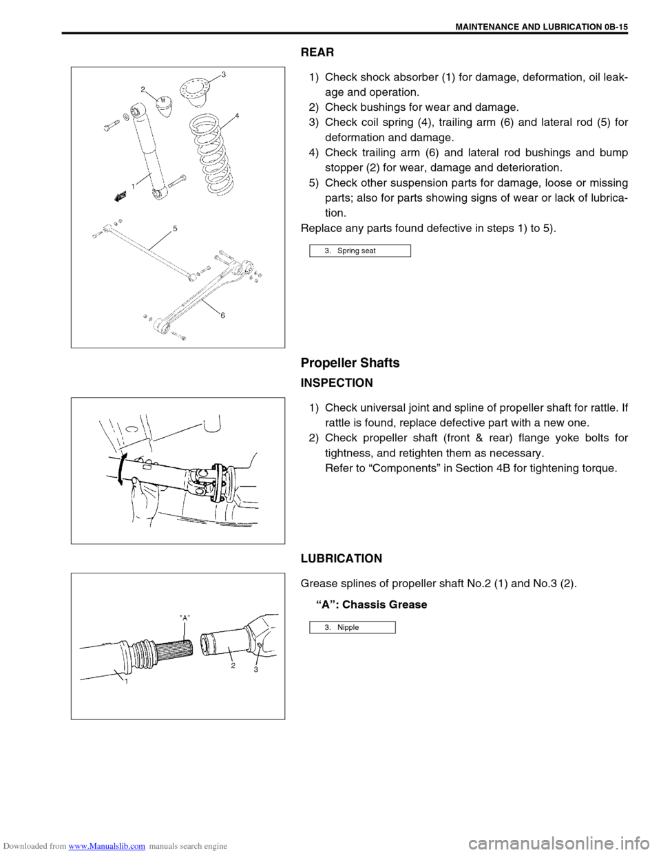
REAR
1) Check shock absorber (1) for damage, deformation, oil leak-
age and operation.
2) Check bushings for wear and damage.
3) Check coil spring (4), trailing arm (6) and lateral rod (5) for
deformation and damage.
4) Check trailing arm (6) and lateral rod bushings and bump
stopper (2) for wear, damage and deterioration.
5) Check other suspension parts for damage, loose or missing
parts; also for parts showing signs of wear or lack of lubrica-
tion.
Replace any parts found defective in steps 1) to 5).
Propeller Shafts
INSPECTION
1) Check universal joint and spline of propeller shaft for rattle. If
rattle is found, replace defective part with a new one.
2) Check propeller shaft (front & rear) flange yoke bolts for
tightness, and retighten them as necessary.
Refer to “Components” in Section 4B for tightening torque.
LUBRICATION
Grease splines of propeller shaft No.2 (1) and No.3 (2).
“A”: Chassis Grease
3. Spring seat
3. Nipple