2005 SUZUKI JIMNY run flat
[x] Cancel search: run flatPage 112 of 687

Downloaded from www.Manualslib.com manuals search engine STEERING, SUSPENSION, WHEELS AND TIRES 3-3
Shimmy, Shake or
VibrationTire or wheel out of balance Balance wheels or replace tire
and/or wheel.
Loose wheel bearings Replace wheel bearing.
Loose wheel hub nuts Retighten.
Worn tie rod ends Replace tie rod end.
Worn king pin bearings or king pins Replace king pin bearing and/or
king pin.
Excessive wheel runout Repair or replace wheel and/or tire.
Blister or bump on tire Replace tire.
Excessively loaded radial runout of tire / wheel
assemblyReplace tire or wheel.
Disturbed front wheel alignment Check and adjust front wheel align-
ment.
Loose or worn steering linkage Tighten or replace steering linkage.
Loose steering gear box bolts Tighten box bolts.
Worn steering knuckle oil seal Replace.
Hard Steering
Bind in tie rod end ball studs or king pin bear-
ingsReplace tie rod end or king pin
bearing.
Disturbed front wheel alignment Check and adjust front wheel align-
ment.
Steering gear box adjustment Check and adjust steering gear
box.
Tire not adequately inflated Inflate tires to proper pressure.
Bind in steering column Repair or replace.
Low fluid level, loose drive belt or malfunction of
power steering system (if equipped with P/S)Check and correct.
Too Much Play in
SteeringWheel bearings worn Replace wheel bearing.
Steering gear box attachments loose Tighten or repair.
Steering gear box adjustments Check and adjust steering gear
box.
Worn steering shaft joints Replace joint.
Worn tie rod ends drug rod ball joints Replace tie rod end.
Worn king pin bearings or king pin Replace king pin bearing and/or
king pin.
Poor Returnability
Bind in tie rod end ball studs Replace tie rod end.
Bind in king pin bearings Replace king pin bearing.
Bind in steering column Repair or replace.
Steering gear box needing lubricant Check, repair or lubricate steering
gear box.
Disturbed front wheel alignment Check and adjust front wheel align-
ment.
Steering gear box not properly adjusted Check and adjust steering gear box
torque.
Tires not adequately inflated Adjust pressure.
Steering Noise
(Rattle or Chuckle)Loose bolts and nuts Retighten.
Broken or otherwise damaged wheel bearings Replace wheel bearing.
Worn or sticky tie rod ends Replace tire rod end.
Linkage joints needing grease Lubricate or replace. Condition Possible Cause Correction
Page 113 of 687

Downloaded from www.Manualslib.com manuals search engine 3-4 STEERING, SUSPENSION, WHEELS AND TIRES
Abnormal Noise,
Front EndWorn, sticky or loose tie rod ends, drug rod ball
joints, king pin bearings or axle shaft jointsReplace tie rod end, king pin bear-
ing or axle shaft joint.
Damaged shock absorbers or mountings Replace or repair.
Worn leading arm bushings Replace.
Worn stabilizer bar bushings Replace.
Worn Iateral rod bushings Replace.
Loose stabilizer bar Tighten bolts or replace bushes.
Loose wheel nuts Tighten wheel nuts.
Loose suspension bolts or nuts Tighten suspension bolts or nuts.
Broken or otherwise damaged wheel bearings Replace wheel bearing.
Broken suspension springs Replace spring.
Wander or Poor
Steering StabilityMismatched or uneven tires Replace tire or inflate tires to
proper pressure.
Loose king pin bearings and tie rod ends Replace king pin bearing or tie rod
end.
Faulty shock absorbers or mounting Replace absorber or repair mount-
ing.
Loose stabilizer bar Tighten or replace stabilizer bar or
bushes.
Broken or sagging springs Replace spring.
Steering gear box not properly adjusted Check or adjust steering gear box
torque.
Front wheel alignment Check and adjust front wheel align-
ment.
Erratic Steering when
BrakingWorn wheel bearings Replace wheel bearing.
Broken or sagging springs Replace spring.
Leaking wheel cylinder or caliper Repair or replace wheel cylinder or
caliper.
Warped discs Replace brake disc.
Badly worn brake linings Replace brake shoe lining.
Drum is out of round in some brakes Replace brake drum.
Wheel tires are inflated unequally Inflate tires to proper pressure.
Defective wheel cylinders Replace or repair wheel cylinder.
Disturbed front wheel alignment Check front wheel alignment
Ride Too Soft
Faulty shock absorber Replace shock absorber.
Suspension bottoms
Overloaded Check loading.
Faulty shocks absorber Replace shock absorber.
Incorrect, broken or sagging springs Replace spring.
Body Leans or Sways
in CornersLoose stabilizer bar Tighten stabilizer bar bolts or
replace bushes.
Faulty shocks absorbers or mounting Replace shock absorber or tighten
mounting.
Broken or sagging springs Replace spring.
Overloaded Check loading.
Cupped Tires
Worn wheel bearings Replace wheel bearing.
Excessive tire or wheel run-out Replace tire or wheel disc.
Tire out of balance Adjust tire balance. Condition Possible Cause Correction
Page 120 of 687

Downloaded from www.Manualslib.com manuals search engine FRONT WHEEL ALIGNMENT 3A-3
Diagnosis
Diagnosis Table
For the details, refer to “Diagnosis Table” in Section 3.
Preliminary Checks Prior To Adjusting Front Wheel Alignment
Steering and vibration complaints are not always the result of improper alignment. An additional item to be
checked is the possibility of tire lead due to worn or improperly manufactured tires. “Lead” is the deviation of the
vehicle from a straight path on a level road without hand pressure on the steering wheel. Section 3 of this man-
ual contains a procedure for determining the presence of a tire lead problem. Before making any adjustment
affecting toe setting, the following checks and inspections should be made to ensure correctness of alignment
readings and alignment adjustments:
1) Check all tires for proper inflation pressures and approximately the same tread wear.
2) Check for loose of king pin bearings. Check tie rod ends; if excessive looseness is noted, it must be cor-
rected before adjusting.
3) Check for run-out of wheels and tires.
4) Check vehicle trim heights; if out of limits and a correction is to be made, it must be made before adjusting
toe.
5) Check for loose of suspension arms.
6) Check for loose or missing stabilizer bar attachments.
7) Consideration must be given to excess loads, such as tool boxes. If this excess load is normally carried in
vehicle, it should remain in vehicle during alignment checks.
8) Consider condition of equipment being used to check alignment and follow manufacturer's instructions.
9) Regardless of equipment used to check alignment, vehicle must be on a level surface both fore and aft and
transversely.
Toe Adjustment
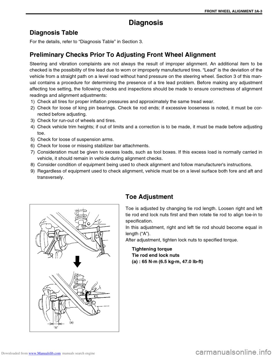
Toe is adjusted by changing tie rod length. Loosen right and left
tie rod end lock nuts first and then rotate tie rod to align toe-in to
specification.
In this adjustment, right and left tie rod should become equal in
length (“A”).
After adjustment, tighten lock nuts to specified torque.
Tightening torque
Tie rod end lock nuts
(a) : 65 N·m (6.5 kg-m, 47.0 lb-ft)
Page 136 of 687

Downloaded from www.Manualslib.com manuals search engine POWER STEERING (P/S) SYSTEM (If equipped) 3B1-5
Steering Wheel Play Check
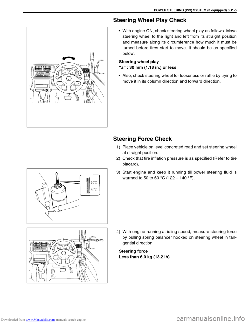
With engine ON, check steering wheel play as follows. Move
steering wheel to the right and left from its straight position
and measure along its circumference how much it must be
turned before tires start to move. It should be as specified
below.
Steering wheel play
“a” : 30 mm (1.18 in.) or less
Also, check steering wheel for looseness or rattle by trying to
move it in its column direction and forward direction.
Steering Force Check
1) Place vehicle on level concreted road and set steering wheel
at straight position.
2) Check that tire inflation pressure is as specified (Refer to tire
placard).
3) Start engine and keep it running till power steering fluid is
warmed to 50 to 60 °C (122 – 140 °F).
4) With engine running at idling speed, measure steering force
by pulling spring balancer hooked on steering wheel in tan-
gential direction.
Steering force
Less than 6.0 kg (13.2 lb)
Page 244 of 687

Downloaded from www.Manualslib.com manuals search engine WHEELS AND TIRES 3F-1
6F1
6F2
6G
3F
8A
8B
8C
8B
8C
8D
8E
9
10
10A
10B
SECTION 3F
WHEELS AND TIRES
CONTENTS
General Description ........................................ 3F-2
Tires .............................................................. 3F-2
Wheels .......................................................... 3F-2
Replacement Tires ........................................ 3F-2
Replacement Wheels ................................ 3F-3
How To Measure Wheel Runout ............... 3F-3
Metric Lug Nuts and Wheel Studs ............. 3F-3
Diagnosis ......................................................... 3F-4
Diagnosis Table ............................................ 3F-4
Balancing Wheels ......................................... 3F-4
General Balance Procedure .......................... 3F-4
Off-vehicle balancing ................................. 3F-4
On-vehicle balancing ................................. 3F-4
Maintenance and Minor Adjustments ........... 3F-6Wheel and Tire.............................................. 3F-6
Studs ......................................................... 3F-6
Matched tires and wheels
(For vehicle equipped with steel
wheels) ...................................................... 3F-6
Inflation of Tires ............................................ 3F-6
Tire placard ............................................... 3F-7
Tire rotation ............................................... 3F-7
On-Vehicle Service ......................................... 3F-8
Wheel ............................................................ 3F-8
Tire ................................................................ 3F-9
Mounting and demounting......................... 3F-9
Repair........................................................ 3F-9
NOTE:
All wheel fasteners are important attaching parts in that they could affect the performance of vital
parts and systems, and/or could result in major repair expense. They must be replaced with one of the
same part number or with an equivalent part if replacement becomes necessary. Do not use a replace-
ment part of lesser quality or substitute design. Torque values must be used as specified during reas-
sembly to assure proper retention of all parts.
There is to be no welding as it may result in extensive damage and weakening of the metal.
Page 569 of 687

Downloaded from www.Manualslib.com manuals search engine 6A1-88 ENGINE MECHANICAL (M13 ENGINE)
Flywheel
If ring gear is damaged, cracked or worn, replace flywheel.
If the surface contacting clutch disc is damaged, or exces-
sively worn, replace flywheel.
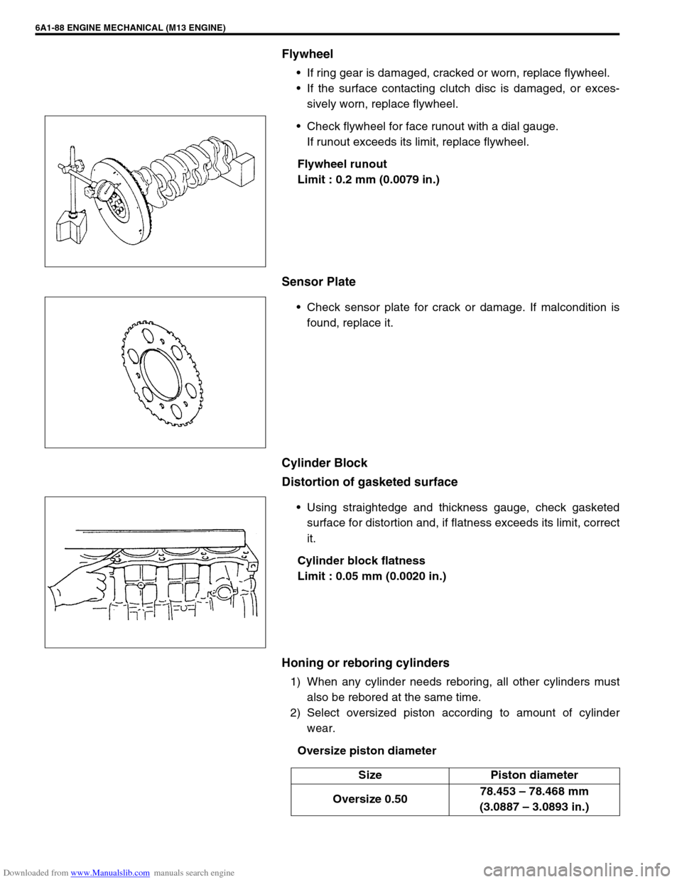
Check flywheel for face runout with a dial gauge.
If runout exceeds its limit, replace flywheel.
Flywheel runout
Limit : 0.2 mm (0.0079 in.)
Sensor Plate
Check sensor plate for crack or damage. If malcondition is
found, replace it.
Cylinder Block
Distortion of gasketed surface
Using straightedge and thickness gauge, check gasketed
surface for distortion and, if flatness exceeds its limit, correct
it.
Cylinder block flatness
Limit : 0.05 mm (0.0020 in.)
Honing or reboring cylinders
1) When any cylinder needs reboring, all other cylinders must
also be rebored at the same time.
2) Select oversized piston according to amount of cylinder
wear.
Oversize piston diameter
Size Piston diameter
Oversize 0.5078.453 – 78.468 mm
(3.0887 – 3.0893 in.)