Page 49 of 687
Downloaded from www.Manualslib.com manuals search engine 0B-18 MAINTENANCE AND LUBRICATION
Steering System
INSPECTION
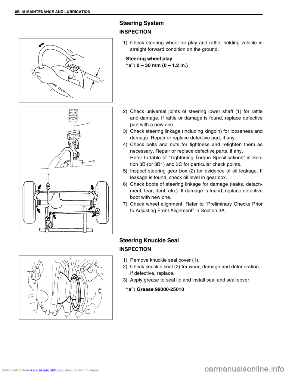
1) Check steering wheel for play and rattle, holding vehicle in
straight forward condition on the ground.
Steering wheel play
“a”: 0 – 30 mm (0 – 1.2 in.)
2) Check universal joints of steering lower shaft (1) for rattle
and damage. If rattle or damage is found, replace defective
part with a new one.
3) Check steering linkage (including kingpin) for looseness and
damage. Repair or replace defective part, if any.
4) Check bolts and nuts for tightness and retighten them as
necessary. Repair or replace defective parts, if any.
Refer to table of “Tightening Torque Specifications” in Sec-
tion 3B (or 3B1) and 3C for particular check points.
5) Inspect steering gear box (2) for evidence of oil leakage. If
leakage is found, check oil level in gear box.
6) Check boots of steering linkage for damage (leaks, detach-
ment, tear, dent, etc.). If damage is found, replace defective
boot with new one.
7) Check wheel alignment. Refer to “Preliminary Checks Prior
to Adjusting Front Alignment” in Section 3A.
Steering Knuckle Seal
INSPECTION
1) Remove knuckle seal cover (1).
2) Check knuckle seal (2) for wear, damage and deterioration.
If defective, replace.
3) Apply grease to seal lip and install seal and seal cover.
“a”: Grease 99000-25010
Page 50 of 687
Downloaded from www.Manualslib.com manuals search engine MAINTENANCE AND LUBRICATION 0B-19
Power Steering (P/S) System (if equipped)
INSPECTION
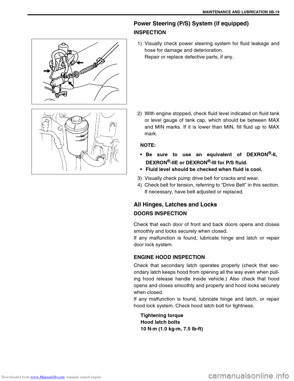
1) Visually check power steering system for fluid leakage and
hose for damage and deterioration.
Repair or replace defective parts, if any.
2) With engine stopped, check fluid level indicated on fluid tank
or level gauge of tank cap, which should be between MAX
and MIN marks. If it is lower than MIN, fill fluid up to MAX
mark.
3) Visually check pump drive belt for cracks and wear.
4) Check belt for tension, referring to “Drive Belt” in this section.
If necessary, have belt adjusted or replaced.
All Hinges, Latches and Locks
DOORS INSPECTION
Check that each door of front and back doors opens and closes
smoothly and locks securely when closed.
If any malfunction is found, lubricate hinge and latch or repair
door lock system.
ENGINE HOOD INSPECTION
Check that secondary latch operates properly (check that sec-
ondary latch keeps hood from opening all the way even when pull-
ing hood release handle inside vehicle.) Also check that hood
opens and closes smoothly and properly and hood locks securely
when closed.
If any malfunction is found, lubricate hinge and latch, or repair
hood lock system. Check hood latch bolt for tightness.
Tightening torque
Hood latch bolts
10 N·m (1.0 kg-m, 7.5 lb-ft)
NOTE:
Be sure to use an equivalent of DEXRON
®-II,
DEXRON
®-IIE or DEXRON®-III for P/S fluid.
Fluid level should be checked when fluid is cool.
Page 60 of 687
Downloaded from www.Manualslib.com manuals search engine HEATER AND VENTILATION 1A-7
Heater Blower Fan Switch
INSPECTION
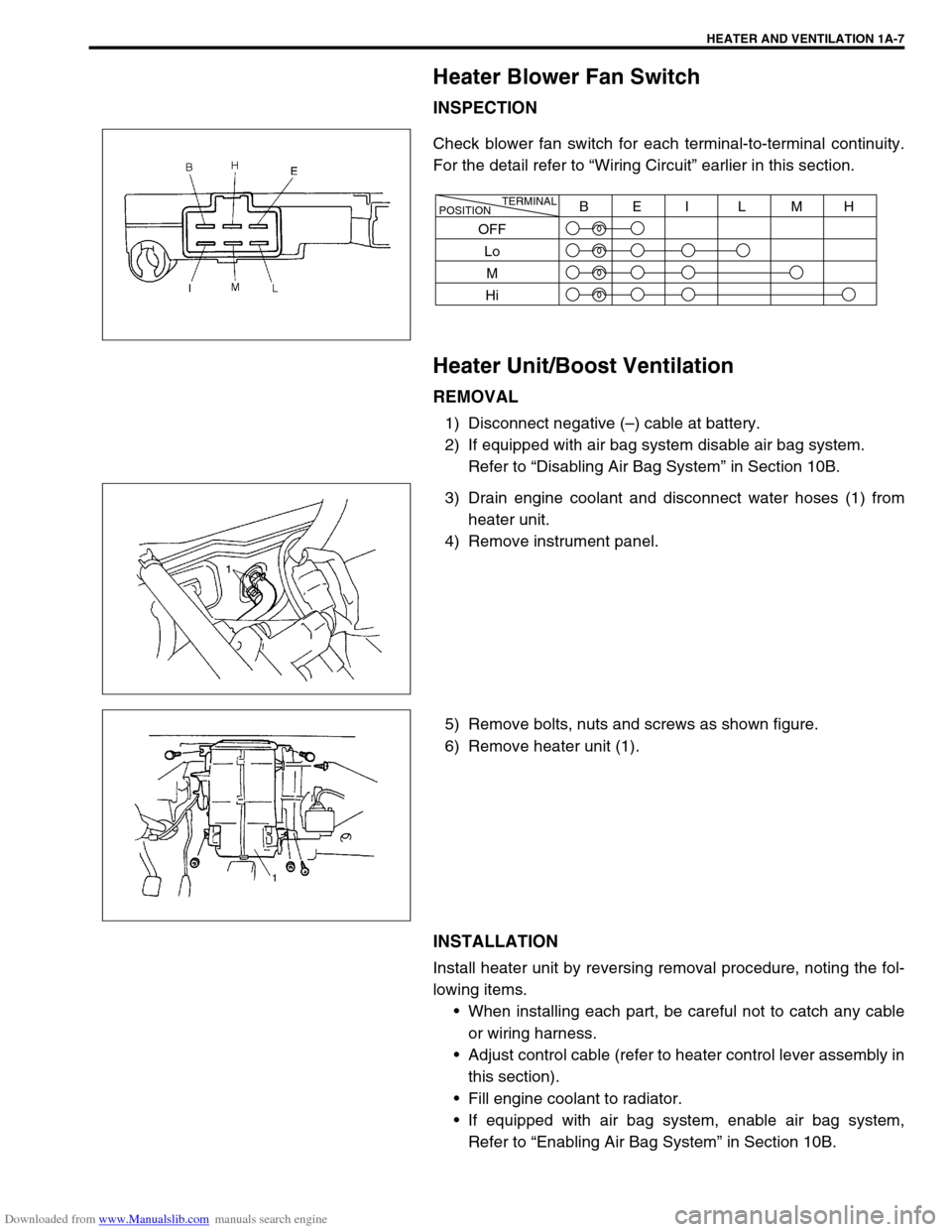
Check blower fan switch for each terminal-to-terminal continuity.
For the detail refer to “Wiring Circuit” earlier in this section.
Heater Unit/Boost Ventilation
REMOVAL
1) Disconnect negative (–) cable at battery.
2) If equipped with air bag system disable air bag system.
Refer to “Disabling Air Bag System” in Section 10B.
3) Drain engine coolant and disconnect water hoses (1) from
heater unit.
4) Remove instrument panel.
5) Remove bolts, nuts and screws as shown figure.
6) Remove heater unit (1).
INSTALLATION
Install heater unit by reversing removal procedure, noting the fol-
lowing items.
When installing each part, be careful not to catch any cable
or wiring harness.
Adjust control cable (refer to heater control lever assembly in
this section).
Fill engine coolant to radiator.
If equipped with air bag system, enable air bag system,
Refer to “Enabling Air Bag System” in Section 10B.
TERMINAL
POSITIONBEI L MH
OFF
Lo
M
Hi
Page 68 of 687

Downloaded from www.Manualslib.com manuals search engine AIR CONDITIONING (OPTIONAL) 1B-7
Abnormal Noise Diagnosis
There are various types of noise, ranging from those produced in the engine compartment to those from the
passenger compartment, also from rumbling noises to whistling noises.
Abnormal noise from compressor
Abnormal noise from magnetic clutch
Abnormal noise from tubing
Abnormal noise from condenser
Condition Possible Cause Correction
During compressor
operation, a rumbling
noise is heard propor-
tional to engine revo-
lutions.Inadequate clearance in piston area (piston or
swash-plate).Repair or replace compressor as
necessary
A loud noise is heard
at a certain rpm, dis-
proportionately to
engine revolution.Loose or faulty compressor drive belt. Adjust drive belt tension, or replace
belt.
Loose compressor mounting bolts. Retighten mounting bolts.
A loud rattle is heard
at low engine rpm.Loose compressor clutch plate bolt. Retighten clutch plate bolt.
Replace compressor if it was oper-
ated in this condition for a long
time.
Condition Possible Cause Correction
A rumbling noise is
heard when compres-
sor is not operating.Worn or damaged bearings. Replace magnet clutch assembly.
A chattering noise is
heard when compres-
sor is engaged.Faulty clutch clearance (excessive). Adjust clutch clearance.
Worn clutch friction surface. Replace magnet clutch assembly.
Compressor oil leaked from lip type seal. Replace lip type seal.
Contaminating the friction surface. Replace compressor body assem-
bly.
Condition Possible Cause Correction
A droning noise is
heard inside vehicle,
but not particularly
noticeable in engine
compartment.Faulty tubing clamps. Reposition clamps or increase the
number of clamps.
Resonance caused by pulsation from variations
in refrigerant pressure.Attach a silencer to tubing, or mod-
ify its position and length.
Condition Possible Cause Correction
Considerable vibra-
tion in condenser.Resonance from condenser bracket and body. Firmly insert a silencer between
condenser bracket and body.
Page 76 of 687
Downloaded from www.Manualslib.com manuals search engine AIR CONDITIONING (OPTIONAL) 1B-15
Compressor Drive Belt
INSPECTION
Check belt for wear and cracks, and replace as required.
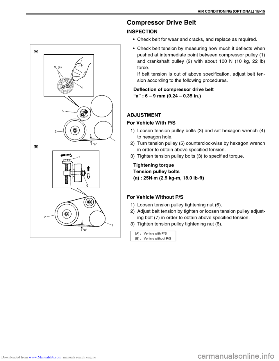
Check belt tension by measuring how much it deflects when
pushed at intermediate point between compressor pulley (1)
and crankshaft pulley (2) with about 100 N (10 kg, 22 lb)
force.
If belt tension is out of above specification, adjust belt ten-
sion according to the following procedures.
Deflection of compressor drive belt
“a” : 6 – 9 mm (0.24 – 0.35 in.)
ADJUSTMENT
For Vehicle With P/S
1) Loosen tension pulley bolts (3) and set hexagon wrench (4)
to hexagon hole.
2) Turn tension pulley (5) counterclockwise by hexagon wrench
in order to obtain above specified tension.
3) Tighten tension pulley bolts (3) to specified torque.
Tightening torque
Tension pulley bolts
(a) : 25N·m (2.5 kg-m, 18.0 lb-ft)
For Vehicle Without P/S
1) Loosen tension pulley tightening nut (6).
2) Adjust belt tension by tighten or loosen tension pulley adjust-
ing bolt (7) in order to obtain above specified tension.
3) Tighten tension pulley tightening nut (6).
[A] : Vehicle with P/S
[B] : Vehicle without P/S
Page 92 of 687
Downloaded from www.Manualslib.com manuals search engine AIR CONDITIONING (OPTIONAL) 1B-31
Condenser Assembly
INSPECTION
Check the following.
Check clog of condenser fins.
If, any clogs are found, condenser fins should be washed
with water, and should be dried with compressed air.
Check condenser fins for leakage and breakage.
If any defects are found, repair or replace condenser.
Check condenser fittings for leakage.
If any defects are found, repair or replace condenser.
REMOVAL
1) Disconnect negative (–) cable at battery.
2) Recover refrigerant from A/C system by referring to “Recov-
ery” in this section.
3) Remove front bumper referring to “Front Bumper” in Section
8.
4) Disconnect A/C condenser cooling fan motor and dual pres-
sure switch connectors.
5) Remove radiator mounting bolts.
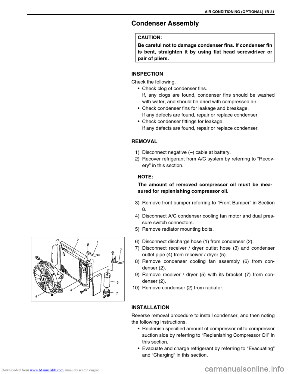
6) Disconnect discharge hose (1) from condenser (2).
7) Disconnect receiver / dryer outlet hose (3) and condenser
outlet pipe (4) from receiver / dryer (5).
8) Remove condenser cooling fan assembly (6) from con-
denser (2).
9) Remove receiver / dryer (5) with its bracket (7) from con-
denser (2).
10) Remove condenser (2) from radiator.
INSTALLATION
Reverse removal procedure to install condenser, and then noting
the following instructions.
Replenish specified amount of compressor oil to compressor
suction side by referring to “Replenishing Compressor Oil” in
this section.
Evacuate and charge refrigerant by referring to “Evacuating”
and “Charging” in this section. CAUTION:
Be careful not to damage condenser fins. If condenser fin
is bent, straighten it by using flat head screwdriver or
pair of pliers.
NOTE:
The amount of removed compressor oil must be mea-
sured for replenishing compressor oil.
Page 94 of 687
Downloaded from www.Manualslib.com manuals search engine AIR CONDITIONING (OPTIONAL) 1B-33
Condenser Cooling Fan Assembly
ASSEMBLY
INSPECTION
1) Check continuity between each two terminals about the con-
denser cooling fan motor (1).
If check results are no continuity, replace condenser cooling
fan motor.
2) Connect battery to condenser cooling fan motor as shown in
figure, then check that the condenser cooling fan motor
operates smoothly.
Reference current of condenser cooling fan motor
approximately 7.5 A at 12 V
REMOVAL
1) Remove front bumper.
2) Disconnect condenser cooling fan motor connector (1).
3) Remove radiator mounting bolts.
4) Remove condenser cooling fan assembly (2) from con-
denser (3).
INSTALLATION
Reverse removal procedure for installation.CAUTION:
Be careful not to damage condenser fins. If condenser fin
is bent, straighten condenser fin by using flat head
screwdriver or pair of pliers.
Page 101 of 687
Downloaded from www.Manualslib.com manuals search engine 1B-40 AIR CONDITIONING (OPTIONAL)
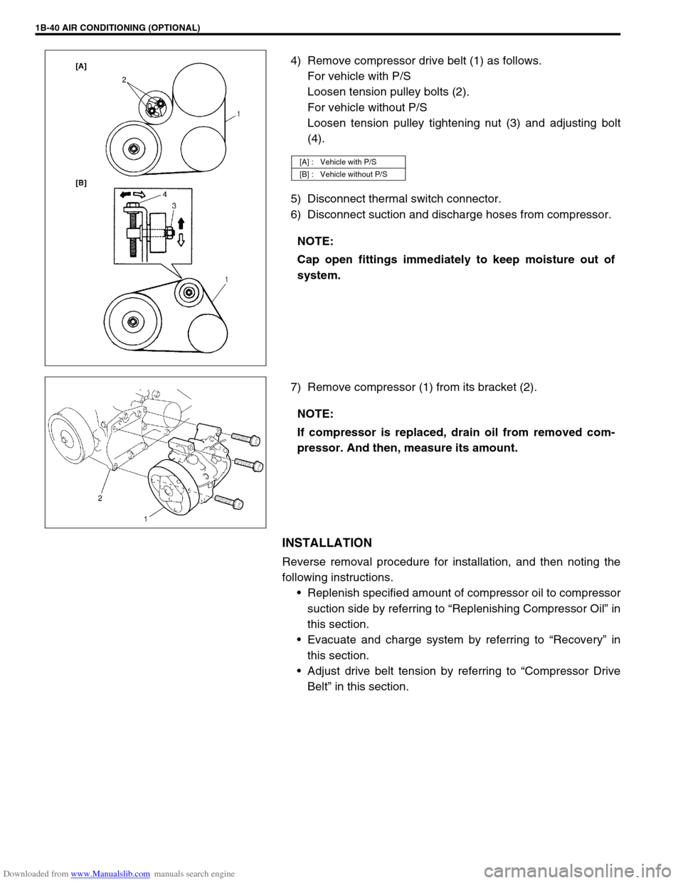
4) Remove compressor drive belt (1) as follows.
For vehicle with P/S
Loosen tension pulley bolts (2).
For vehicle without P/S
Loosen tension pulley tightening nut (3) and adjusting bolt
(4).
5) Disconnect thermal switch connector.
6) Disconnect suction and discharge hoses from compressor.
7) Remove compressor (1) from its bracket (2).
INSTALLATION
Reverse removal procedure for installation, and then noting the
following instructions.
Replenish specified amount of compressor oil to compressor
suction side by referring to “Replenishing Compressor Oil” in
this section.
Evacuate and charge system by referring to “Recovery” in
this section.
Adjust drive belt tension by referring to “Compressor Drive
Belt” in this section.
[A] : Vehicle with P/S
[B] : Vehicle without P/S
NOTE:
Cap open fittings immediately to keep moisture out of
system.
NOTE:
If compressor is replaced, drain oil from removed com-
pressor. And then, measure its amount.