Page 21 of 687

Downloaded from www.Manualslib.com manuals search engine 0A-16 GENERAL INFORMATION
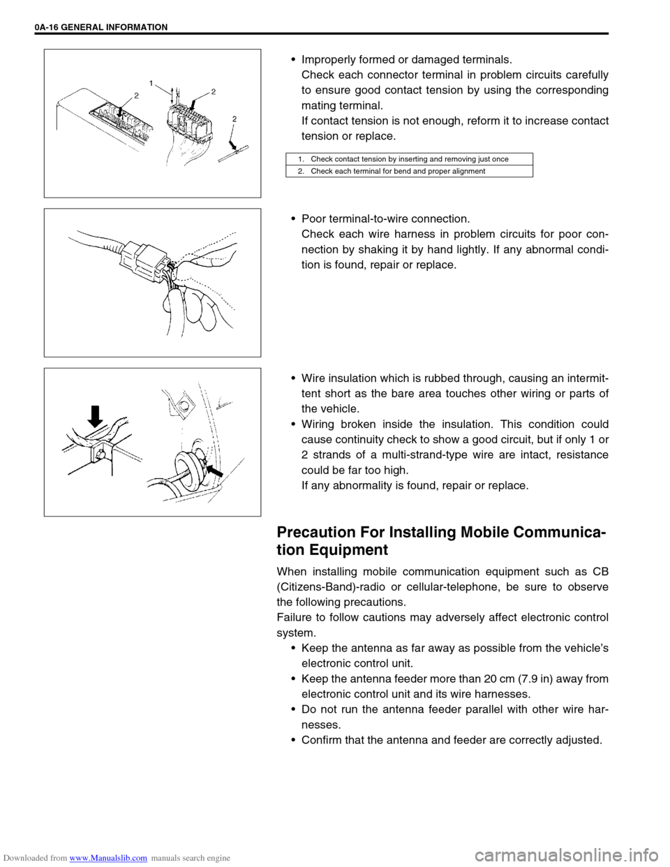
Improperly formed or damaged terminals.
Check each connector terminal in problem circuits carefully
to ensure good contact tension by using the corresponding
mating terminal.
If contact tension is not enough, reform it to increase contact
tension or replace.
Poor terminal-to-wire connection.
Check each wire harness in problem circuits for poor con-
nection by shaking it by hand lightly. If any abnormal condi-
tion is found, repair or replace.
Wire insulation which is rubbed through, causing an intermit-
tent short as the bare area touches other wiring or parts of
the vehicle.
Wiring broken inside the insulation. This condition could
cause continuity check to show a good circuit, but if only 1 or
2 strands of a multi-strand-type wire are intact, resistance
could be far too high.
If any abnormality is found, repair or replace.
Precaution For Installing Mobile Communica-
tion Equipment
When installing mobile communication equipment such as CB
(Citizens-Band)-radio or cellular-telephone, be sure to observe
the following precautions.
Failure to follow cautions may adversely affect electronic control
system.
Keep the antenna as far away as possible from the vehicle’s
electronic control unit.
Keep the antenna feeder more than 20 cm (7.9 in) away from
electronic control unit and its wire harnesses.
Do not run the antenna feeder parallel with other wire har-
nesses.
Confirm that the antenna and feeder are correctly adjusted.
1. Check contact tension by inserting and removing just once
2. Check each terminal for bend and proper alignment
Page 58 of 687

Downloaded from www.Manualslib.com manuals search engine HEATER AND VENTILATION 1A-5
Heater Blower Resistor
REMOVAL
1) Disconnect negative (–) cable at battery.
2) Disable air bag system, if equipped.
Refer to “Disabling Air Bag System” in Section 10B.
3) Disconnect resistor coupler.
4) Remove blower motor resistor (3) as shown figure.
INSPECTION
Measure each terminal-to-terminal resistance on resistor
If measured resistance is incorrect, replace heater blower motor
resistor.
Heater blower resistor resistance
Me-Lo: approx. 2.4
Ω
Me-Hi: approx. 1.2
Ω
INSTALLATION
1) Reverse removal procedure for installation.
2) Enable air bag system, if equipped.
Refer to “Enabling Air Bag System” in Section 10B.
Heater Control Lever Assembly
REMOVAL
1) Disconnect negative (–) cable at battery.
2) Disable air bag system, if equipped.
Refer to “Disabling Air Bag System” in Section 10B.
3) Remove meter cluster hood, ashtray, center garnish, instru-
ment glove box and radio or accessory case (if equipped),
Then remove mounting screws (2) from heater control lever
assembly (1).
1. Heater unit
2. Blower motor
Page 671 of 687

Downloaded from www.Manualslib.com manuals search engine 6H-4 CHARGING SYSTEM
When keeping battery on vehicle over a long period of time, follow
instructions given below.
Weekly, start the engine and run it until it reaches normal
operating temperature with engine speed of 2,000 to 3,000
rpm. Make sure all electric switches are off before storing the
vehicle.
Recharge the battery twice a month to prevent it from dis-
charging excessively. This is especially important when
ambient temperature is low.
The battery discharges even when it is not used, while vehi-
cles are being stored. Battery electrolyte can freeze and bat-
tery case can crack at cold ambient condition if battery is not
properly charged.
2) Keep the battery cable connections clean.
The cable connections, particularly at the positive (+) termi-
nal post, tend to become corroded. The product of corrosion,
or rust, on the mating faces of conductors resists the flow of
current.
Clean the terminals and fittings periodically to ensure good
metal-to-metal contact, and grease the connections after
each cleaning to protect them against rusting.
3) Be always in the know as to the state of charge of the bat-
tery. The simplest way to tell the state of charge is to carry
out a hydrometer test. The hydrometer is an instrument for
measuring the specific gravity (S.G.) of the battery electro-
lyte. The S.G. of the electrolyte is indicative of the state of
charge. Refer to “HYDROMETER TEST” in this section.
Generator
The generator is a small and high performance type with an IC regulator incorporated.
The internal components are connected electrically as shown below figure.
The generator features are as follows:
Solid state regulator is mounted inside the generator.
All regulator components are enclosed into a solid mold.
This unit along with the brush holder assembly is attached to the rear housing.
The IC regulator uses integrated circuits and controls the voltage produced by the generator, and the volt-
age setting cannot be adjusted.
The generator rotor bearings contain enough grease to eliminate the need for periodic lubrication. Two
brushes carry current through the two slip rings to the field coil mounted on the rotor, and under normal con-
ditions will provide long period of attention-free service.
The stator windings are assembled on the inside of a laminated core that forms part of the generator frame.
A condenser mounted in the rear housing suppresses radio noise.