2005 SUZUKI JIMNY front
[x] Cancel search: frontPage 134 of 687

Downloaded from www.Manualslib.com manuals search engine POWER STEERING (P/S) SYSTEM (If equipped) 3B1-3
Diagnosis
Diagnosis Table
Condition Possible Cause Correction
Steering wheel feels
heavy
(at low speed)Fluid deteriorated, low viscosity, different type of
fluid mixedChange fluid.
Pipes or hoses deformed, air entering through
jointCorrect or replace.
Insufficient air bleeding from piping Bleed air.
Belt worn, lacking in tension Adjust belt tension or replace belt
as necessary.
Tire inflation pressure too low Inflate tire.
Wheel alignment out of adjustment Adjust front wheel alignment.
Steering wheel installed improperly (twisted) Install steering wheel correctly.
Hydraulic pressure failing to rise (See NOTE
“A”.)Replace P/S pump.
Slow hydraulic pressure rise (See NOTE “A”.)
Steering wheel feels
heavy momentarily
when turning it to the
left or right.Air drawn in due to insufficient amount of fluid Add fluid and bleed air.
Slipping belt Adjust belt tension or replace belt
as necessary.
No idle-up (See NOTE
“B”.)Defective pressure switch Replace pressure switch
(terminal set).
NOTE:
“A” : Be sure to warm up engine fully before performing this check. Pump vanes are sometimes
hard to come out where temperature is low.
“B” : Acceptable if idling speed does not drop.
Condition Possible Cause Correction
Steering wheel returns
slowly from turns.
(See NOTE “C”.)Dust or foreign object mixed in fluid Change fluid.
Deformed pipes or hoses Correct or replace.
Steering column installed improperly Install correctly.
Wheel alignment maladjusted Adjust.
Linkage or joints not operating smoothly Correct.
Vehicle pulls to one
side during straight
driving.Low or uneven tire inflation pressure Inflate tire (s) as necessary.
Wheel alignment maladjusted Adjust.
Defective spool valve Replace gear box assembly.
Steering wheel play is
large and vehicle wan-
ders.Loose steering shaft nut Retighten.
Loose linkage or joint Retighten.
Loose gear box fixing bolt Retighten.
Front wheel bearing worn Replace.
Fluid leakage
Loose joints of hydraulic pressure pipes and
hosesRetighten.
Deformed or damaged pipes or hoses Correct or replace.
Gear box Replace gear box assembly.
Page 139 of 687

Downloaded from www.Manualslib.com manuals search engine 3B1-8 POWER STEERING (P/S) SYSTEM (If equipped)
Air Bleeding Procedure
AIR BLEEDING FROM SYSTEM
1) Jack up the front end of vehicle and apply rigid rack.
2) Fill P/S fluid reservoir with fluid up to specified level.
3) With engine running at idling speed, add fluid up to specified
level.
4) When fluid stops reducing, stop engine and leave P/S sys-
tem as it is for about 10 minutes.
5) After running engine at idling speed for 1 minute, stop it.
6) As a final step, check to make sure that fluid is up to speci-
fied level.
7) Check steering condition and P/S system for fluid leakage.
AIR BLEEDING FROM GEAR BOX
1) Remove steering gear box from vehicle referring to “Power
Steering (P/S) Gear Box” in this section.
2) Install special tool as shown.
Special tool
(A) : 09945-35010 CAUTION:
When air bleeding is not complete, it is indicated by
foaming fluid on level gauge or humming noise from P/S
pump.
NOTE:
Bleed air from system when P/S system has been ser-
viced in any way other than replacement of steering gear
box (e.g., disconnection of piping, replacement of P/S
pump). Never operate steering system while servicing.
Or Air Bleeding from gear box must be performed.
NOTE:
Bleed air from gear box:
When steering gear box has been replaced with a new
one.
When entry of air into hydraulic circuit of steering gear
box is suspected.
1. Steering gear box 3. High pressure hose / pipe
2. Low pressure hose / pipe
Page 151 of 687

Downloaded from www.Manualslib.com manuals search engine 3B1-20 POWER STEERING (P/S) SYSTEM (If equipped)
Install pitman arm (1) to sector shaft (2) of P/S gear box (3)
with match marks “A” and “B” aligned as shown in figure and
torque to specification.
Tightening torque
Pitman arm mounting nut
(a) : 135 N·m (13.5 kg-m, 98.0 lb-ft)
Install lower shaft by the following steps.
1) Align flat part of steering gear box worm shaft (1) with bolt
hole in lower joint as shown. Then insert lower joint (2) onto
worm shaft.
2) Be sure that front wheels and steering wheel are in straight-
forward state and insert upper joint onto steering shaft.
3) Torque lower shaft joint bolt to specification.
Tightening torque
Steering shaft lower joint bolt
(a) : 25 N·m (2.5 kg-m, 18.0 lb-ft)
Fill engine coolant to radiator.
Bleed air in P/S circuit referring to “Air Bleeding Procedure”
in this section.
Page 155 of 687

Downloaded from www.Manualslib.com manuals search engine 3C-2 STEERING WHEEL AND COLUMN
General Description
This double tube type steering column has the following three important features in addition to the steering func-
tion:
The column is energy absorbing, designed to compress in a front-end collision.
The ignition switch and lock are mounted conveniently on this column.
With the column mounted lock, the ignition and steering operations can be locked to inhibit theft of the vehi-
cle.
To insure the energy absorbing action, it is important that only the specified screws, bolts and nuts be used as
designated and that they are tightened to the specified torque.
When the column assembly is removed from the vehicle, special care must be taken in handling it. Use of a
steering wheel puller other than the one recommended in this manual or a sharp blow on the end of the steering
shaft, leaning on the assembly, or dropping the assembly could shear the plastic shear pins which maintain col-
umn length and position.
The driver air bag (inflator) module is one of the supplemental restraint (air bag) system components and is
mounted to the center of the steering wheel. During certain frontal crashes, the air bag system supplements the
restraint of the driver’s and passenger’s seat belts by deploying the air bags.
The air bag (inflator) module should be handled with care to prevent accidental deployment. When servicing, be
sure to observe all WARNINGS and CAUTIONS in this section and “Service Precautions” in Section 10B.
1. Driver air bag (inflator) module 6. Steering column upper cover 11. Steering lower shaft
2. Steering wheel 7. Steering column lower cover [A] : For vehicle with air bag system
3. Steering wheel side cap 8. Steering column assembly [B] : For vehicle without air bag system
4. Steering wheel nut 9. Steering lock assembly (ignition switch)
5. Combination switch or contact coil and com-
bination switch assembly10. Steering column hole cover
Page 160 of 687

Downloaded from www.Manualslib.com manuals search engine STEERING WHEEL AND COLUMN 3C-7
5) Remove steering wheel (1) with special tool.
Special tool
(A) : 09944-36011
INSTALLATION
1) Check that vehicle’s front tires are at straight-ahead position.
If equipped with air bag system, align contact coil to original
position referring to “Centering Contact Coil” in this section.
2) Install steering wheel as follows.
For vehicle without air bag system
a) Apply grease to contact plate (1).
“A” : Grease 99000-25290
b) Install steering wheel onto shaft, aligning them by match
marks.
For vehicle with air bag system
Install steering wheel to steering shaft with 2 lugs (2) on con-
tact coil fitted in two grooves (3) in the back of steering wheel
and also aligning marks (4) on steering wheel and steering
shaft. CAUTION:
Do not hammer the end of the shaft. Hammering it will
loosen the plastic shear pins which maintain the column
length and impair the collapsible design of the column.
CAUTION:
For vehicle with air bag system
These two conditions are prerequisite for installation of
steering wheel. If steering wheel has been installed with-
out these conditions, contact coil will break when steer-
ing wheel is turned.
[A] : For vehicle without air bag system
[B] : For vehicle with air bag system
Page 161 of 687

Downloaded from www.Manualslib.com manuals search engine 3C-8 STEERING WHEEL AND COLUMN
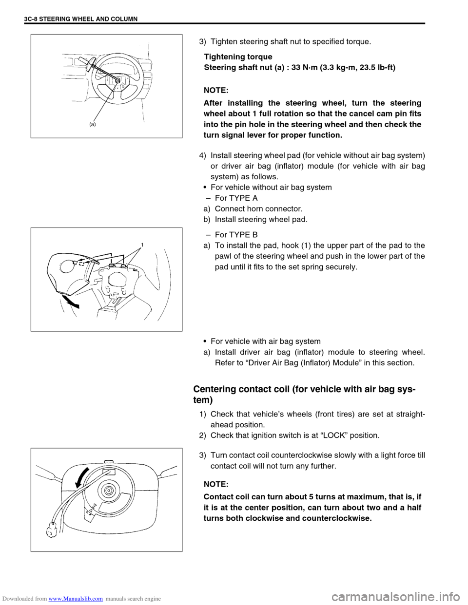
3) Tighten steering shaft nut to specified torque.
Tightening torque
Steering shaft nut (a) : 33 N·m (3.3 kg-m, 23.5 lb-ft)
4) Install steering wheel pad (for vehicle without air bag system)
or driver air bag (inflator) module (for vehicle with air bag
system) as follows.
For vehicle without air bag system
–For TYPE A
a) Connect horn connector.
b) Install steering wheel pad.
–For TYPE B
a) To install the pad, hook (1) the upper part of the pad to the
pawl of the steering wheel and push in the lower part of the
pad until it fits to the set spring securely.
For vehicle with air bag system
a) Install driver air bag (inflator) module to steering wheel.
Refer to “Driver Air Bag (Inflator) Module” in this section.
Centering contact coil (for vehicle with air bag sys-
tem)
1) Check that vehicle’s wheels (front tires) are set at straight-
ahead position.
2) Check that ignition switch is at “LOCK” position.
3) Turn contact coil counterclockwise slowly with a light force till
contact coil will not turn any further. NOTE:
After installing the steering wheel, turn the steering
wheel about 1 full rotation so that the cancel cam pin fits
into the pin hole in the steering wheel and then check the
turn signal lever for proper function.
NOTE:
Contact coil can turn about 5 turns at maximum, that is, if
it is at the center position, can turn about two and a half
turns both clockwise and counterclockwise.
Page 163 of 687

Downloaded from www.Manualslib.com manuals search engine 3C-10 STEERING WHEEL AND COLUMN
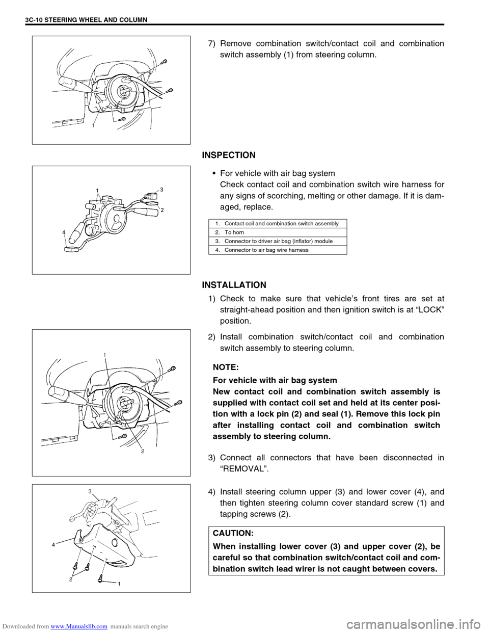
7) Remove combination switch/contact coil and combination
switch assembly (1) from steering column.
INSPECTION
For vehicle with air bag system
Check contact coil and combination switch wire harness for
any signs of scorching, melting or other damage. If it is dam-
aged, replace.
INSTALLATION
1) Check to make sure that vehicle’s front tires are set at
straight-ahead position and then ignition switch is at “LOCK”
position.
2) Install combination switch/contact coil and combination
switch assembly to steering column.
3) Connect all connectors that have been disconnected in
“REMOVAL”.
4) Install steering column upper (3) and lower cover (4), and
then tighten steering column cover standard screw (1) and
tapping screws (2).
1. Contact coil and combination switch assembly
2. To horn
3. Connector to driver air bag (inflator) module
4. Connector to air bag wire harness
NOTE:
For vehicle with air bag system
New contact coil and combination switch assembly is
supplied with contact coil set and held at its center posi-
tion with a lock pin (2) and seal (1). Remove this lock pin
after installing contact coil and combination switch
assembly to steering column.
CAUTION:
When installing lower cover (3) and upper cover (2), be
careful so that combination switch/contact coil and com-
bination switch lead wirer is not caught between covers.
Page 165 of 687

Downloaded from www.Manualslib.com manuals search engine 3C-12 STEERING WHEEL AND COLUMN
REMOVAL
1) Disconnect negative battery cable at battery terminal.
2) For vehicle equipped with air bag system, disable air bag
system referring to “Disabling Air Bag System” in Section
10B.
3) If necessary, remove steering wheel and combination switch
assembly referring to “Steering Wheel” and “Combination
switch/Contact Coil and Combination Switch Assembly” in
this section.
If not removing steering wheel and/or combination switch
assembly, perform the following procedure.
a) Turn steering wheel so that vehicle’s front tires are at
straight ahead position.
b) Turn ignition switch to “LOCK” position and remove key.
4) Remove steering column hole cover (1).
5) Disconnect all connectors of the following parts.
Combination switch/contact coil and combination switch
assembly.
Ignition switch.
Immobilizer control system parts (if equipped).
6) Remove joint bolt (steering column side) (3) and loosen joint
bolt (steering gear box side).
7) Remove steering column mounting nuts (2) and bolts (1).WARNING:
For vehicle with air bag system
Never rest a steering column assembly on the steering
wheel with the air bag (inflator) module face down and
column vertical. Otherwise, personal injury may result.