Page 159 of 687
Downloaded from www.Manualslib.com manuals search engine 3C-6 STEERING WHEEL AND COLUMN
REMOVAL
1) Disconnect negative battery cable at battery terminal.
2) Remove steering wheel pad (for vehicle without air bag sys-
tem) or driver air bag (inflator) module (for vehicle with air
bag system) as follows.
Vehicle without air bag system for TYPE A
a) Remove steering wheel pad.
b) Disconnect horn connector.
Vehicle without air bag system for TYPE B
a) As shown in the figure, while pushing the set spring (1) with
a screwdriver or the like inserted in the hole of the steering
wheel, pull the lower part of the pad forward and remove
the steering wheel pad.
Vehicle with air bag system
a) Remove driver air bag (inflator) module from steering wheel
referring to “Driver Air Bag (Inflator) Module” in this section.
3) Remove steering shaft nut.
4) Make alignment marks (1) on steering wheel and shaft for a
guide during reinstallation.
[A] : For TYPE A
[B] : For TYPE B
Page 161 of 687
Downloaded from www.Manualslib.com manuals search engine 3C-8 STEERING WHEEL AND COLUMN
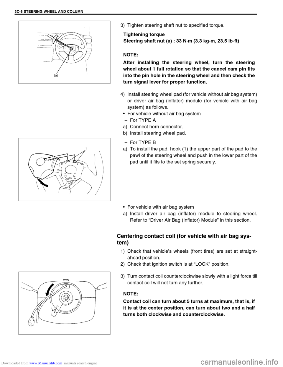
3) Tighten steering shaft nut to specified torque.
Tightening torque
Steering shaft nut (a) : 33 N·m (3.3 kg-m, 23.5 lb-ft)
4) Install steering wheel pad (for vehicle without air bag system)
or driver air bag (inflator) module (for vehicle with air bag
system) as follows.
For vehicle without air bag system
–For TYPE A
a) Connect horn connector.
b) Install steering wheel pad.
–For TYPE B
a) To install the pad, hook (1) the upper part of the pad to the
pawl of the steering wheel and push in the lower part of the
pad until it fits to the set spring securely.
For vehicle with air bag system
a) Install driver air bag (inflator) module to steering wheel.
Refer to “Driver Air Bag (Inflator) Module” in this section.
Centering contact coil (for vehicle with air bag sys-
tem)
1) Check that vehicle’s wheels (front tires) are set at straight-
ahead position.
2) Check that ignition switch is at “LOCK” position.
3) Turn contact coil counterclockwise slowly with a light force till
contact coil will not turn any further. NOTE:
After installing the steering wheel, turn the steering
wheel about 1 full rotation so that the cancel cam pin fits
into the pin hole in the steering wheel and then check the
turn signal lever for proper function.
NOTE:
Contact coil can turn about 5 turns at maximum, that is, if
it is at the center position, can turn about two and a half
turns both clockwise and counterclockwise.
Page 163 of 687
Downloaded from www.Manualslib.com manuals search engine 3C-10 STEERING WHEEL AND COLUMN
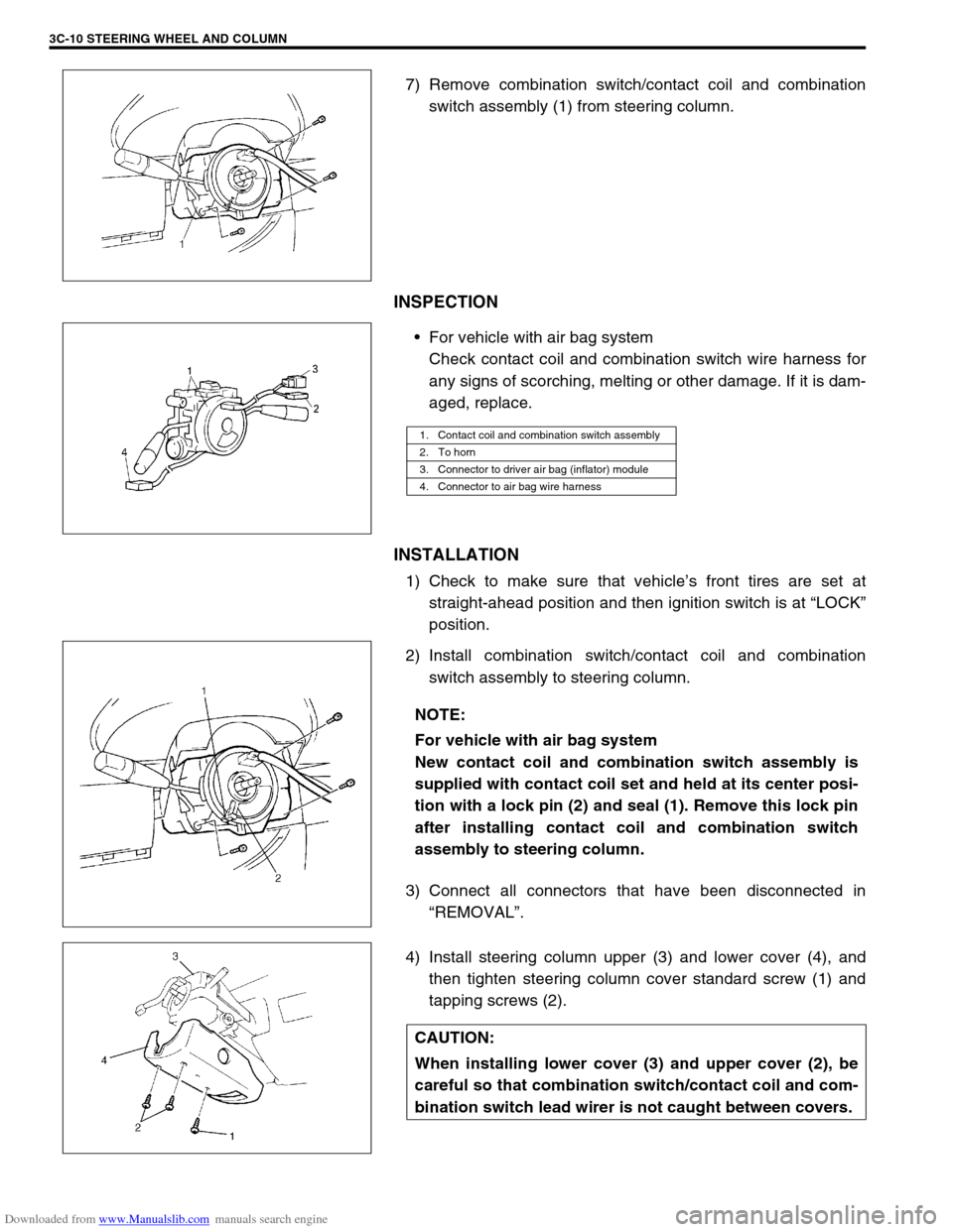
7) Remove combination switch/contact coil and combination
switch assembly (1) from steering column.
INSPECTION
For vehicle with air bag system
Check contact coil and combination switch wire harness for
any signs of scorching, melting or other damage. If it is dam-
aged, replace.
INSTALLATION
1) Check to make sure that vehicle’s front tires are set at
straight-ahead position and then ignition switch is at “LOCK”
position.
2) Install combination switch/contact coil and combination
switch assembly to steering column.
3) Connect all connectors that have been disconnected in
“REMOVAL”.
4) Install steering column upper (3) and lower cover (4), and
then tighten steering column cover standard screw (1) and
tapping screws (2).
1. Contact coil and combination switch assembly
2. To horn
3. Connector to driver air bag (inflator) module
4. Connector to air bag wire harness
NOTE:
For vehicle with air bag system
New contact coil and combination switch assembly is
supplied with contact coil set and held at its center posi-
tion with a lock pin (2) and seal (1). Remove this lock pin
after installing contact coil and combination switch
assembly to steering column.
CAUTION:
When installing lower cover (3) and upper cover (2), be
careful so that combination switch/contact coil and com-
bination switch lead wirer is not caught between covers.
Page 172 of 687
Downloaded from www.Manualslib.com manuals search engine STEERING WHEEL AND COLUMN 3C-19
6) Check steering shaft joints and shaft for any damages such
as crack, breakage, malfunction or excessive play.
If anything is found faulty, replace as lower joint assembly or
column assembly.
7) Check steering shaft for smooth rotation.
If found defective, replace as column assembly.
8) Check steering shaft and column for bend, cracks or defor-
mation.
If found defective, replace.
Tightening Torque Specifications
Required Service Material
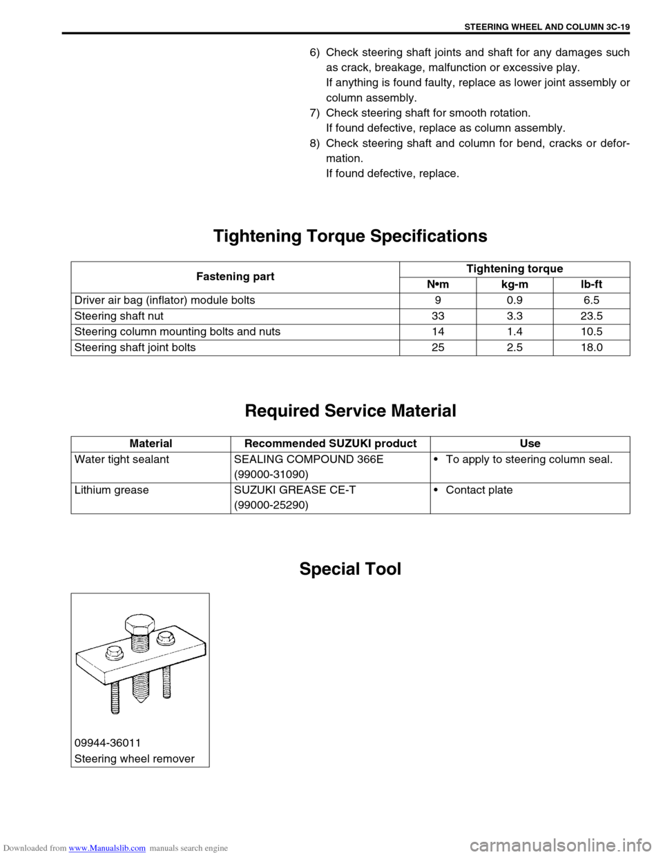
Special Tool
Fastening partTightening torque
Nm kg-m lb-ft
Driver air bag (inflator) module bolts 9 0.9 6.5
Steering shaft nut 33 3.3 23.5
Steering column mounting bolts and nuts 14 1.4 10.5
Steering shaft joint bolts 25 2.5 18.0
Material Recommended SUZUKI product Use
Water tight sealant SEALING COMPOUND 366E
(99000-31090)To apply to steering column seal.
Lithium grease SUZUKI GREASE CE-T
(99000-25290)Contact plate
09944-36011
Steering wheel remover
Page 197 of 687
Downloaded from www.Manualslib.com manuals search engine 3D-24 FRONT SUSPENSION
11) Using hydraulic press (1) and special tool remove wheel
bearing (2).
Special tool
(A) : 09913-75520
12) Remove hub bolts from hub.
INSTALLATION
1) Insert new stud in hub hole. Rotate stud slowly to assure ser-
rations are aligned with those made by original bolt.
2) Using special tool, press-fit wheel bearing (3) until its end
contacts stepped surface of wheel hub (4).
Special tool
(A) : 09944-78210
3) Install bearing circlip.
4) Drive in wheel bearing oil seal (1) by using special tools.
Special tool
(B) : 09944-66010
(C) : 09924-74510
1. Oil hydraulic press
2. Hub bolt
CAUTION:
Press-fit wheel bearing (3) vertically to hub (4).
1. Oil hydraulic press
2. Steel plate
Page 236 of 687
Downloaded from www.Manualslib.com manuals search engine REAR SUSPENSION 3E-17
16) Upon completion of all jobs, depress brake pedal with about
30 kg (66 lbs) load over ten times so as to obtain proper
drum-to shoe clearance.
Adjust parking brake cable. (For adjustment, refer to “Parking
Brake Check and Adjustment” in Section 5.)
17) Tighten parking brake lever cover screws.
18) Check to ensure that brake drum is free from dragging and
proper braking is obtained. Then remove vehicle from hoist
and perform brake test (foot brake and parking brake).
19) Check each installed part for oil leakage.
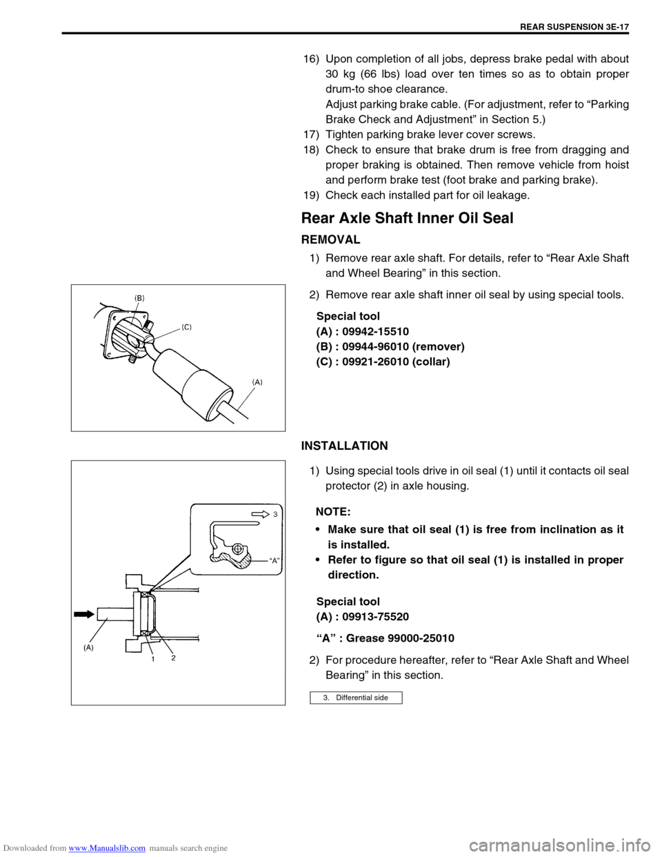
Rear Axle Shaft Inner Oil Seal
REMOVAL
1) Remove rear axle shaft. For details, refer to “Rear Axle Shaft
and Wheel Bearing” in this section.
2) Remove rear axle shaft inner oil seal by using special tools.
Special tool
(A) : 09942-15510
(B) : 09944-96010 (remover)
(C) : 09921-26010 (collar)
INSTALLATION
1) Using special tools drive in oil seal (1) until it contacts oil seal
protector (2) in axle housing.
Special tool
(A) : 09913-75520
“A” : Grease 99000-25010
2) For procedure hereafter, refer to “Rear Axle Shaft and Wheel
Bearing” in this section.
NOTE:
Make sure that oil seal (1) is free from inclination as it
is installed.
Refer to figure so that oil seal (1) is installed in proper
direction.
3. Differential side
Page 248 of 687
Downloaded from www.Manualslib.com manuals search engine WHEELS AND TIRES 3F-5
WARNING:
Wheel spin should be limited to 35 mph (55 km/h) as indicated on speedometer.
This limit is necessary because speedometer only indicates one-half of actual wheel speed when one
drive wheel is spinning and the other drive wheel is stopped.
Unless care is taken in limiting drive wheel spin, spinning wheel can reach excessive speeds. This
can result in possible tire disintegration or differential failure, which could cause serious personal
injury or extensive vehicle damage.
CAUTION:
For vehicle equipped with ABS, using on-vehicle balancing method with ignition switch ON may set
malfunction diagnostic trouble code (DTC) of ABS even when system is in good condition.
Never turn ignition switch ON while spinning wheel.
Page 249 of 687
Downloaded from www.Manualslib.com manuals search engine 3F-6 WHEELS AND TIRES
Maintenance and Minor Adjustments
Wheel and Tire
Wheel repairs that use welding, heating, or peening are not approved. All damaged wheels should be replaced.
Studs
If a broken stud is found, see Section 3E (rear) or Section 3D (front) for Note and Replacement procedure.
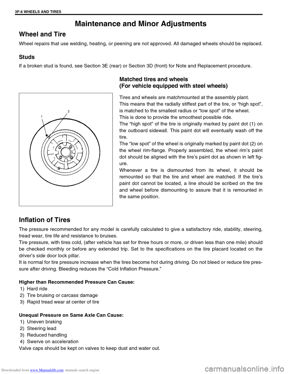
Matched tires and wheels
(For vehicle equipped with steel wheels)
Tires and wheels are matchmounted at the assembly plant.
This means that the radially stiffest part of the tire, or “high spot”,
is matched to the smallest radius or “low spot” of the wheel.
This is done to provide the smoothest possible ride.
The “high spot” of the tire is originally marked by paint dot (1) on
the outboard sidewall. This paint dot will eventually wash off the
tire.
The “low spot” of the wheel is originally marked by paint dot (2) on
the wheel rim-flange. Properly assembled, the wheel rim’s paint
dot should be aligned with the tire’s paint dot as shown in left fig-
ure.
Whenever a tire is dismounted from its wheel, it should be
remounted so that the tire and wheel are matched. If the tire’s
paint dot cannot be located, a line should be scribed on the tire
and wheel before dismounting to assure that it is remounted in
the same position.
Inflation of Tires
The pressure recommended for any model is carefully calculated to give a satisfactory ride, stability, steering,
tread wear, tire life and resistance to bruises.
Tire pressure, with tires cold, (after vehicle has set for three hours or more, or driven less than one mile) should
be checked monthly or before any extended trip. Set to the specifications on the tire placard located on the
driver’s side door lock pillar.
It is normal for tire pressure increase when the tires become hot during driving. Do not bleed or reduce tire pres-
sure after driving. Bleeding reduces the “Cold Inflation Pressure.”
Higher than Recommended Pressure Can Cause:
1) Hard ride
2) Tire bruising or carcass damage
3) Rapid tread wear at center of tire
Unequal Pressure on Same Axle Can Cause:
1) Uneven braking
2) Steering lead
3) Reduced handling
4) Swerve on acceleration
Valve caps should be kept on valves to keep dust and water out.