2005 SUZUKI JIMNY drive
[x] Cancel search: drivePage 66 of 687

Downloaded from www.Manualslib.com manuals search engine AIR CONDITIONING (OPTIONAL) 1B-5
Diagnosis
General Diagnosis Table
Condition Possible Cause Correction
Cool air won’t come
out (A/C system won’t
operative)No refrigerant Perform recover, evacuation and charging.
Fuse blown Check fuses in main and circuit fuse
boxes, and check short circuit to ground.
A/C switch faulty Check A/C switch.
Blower fan switch faulty Check blower fan switch referring to Sec-
tion 1A.
A/C evaporator thermistor faulty Check A/C evaporator thermistor.
Dual pressure switch faulty Check dual pressure switch.
Wiring or grounding faulty Repair as necessary.
ECT sensor faulty Check ECT sensor referring to Section 6E.
ECM and its circuit faulty Check ECM and its circuit referring to Sec-
tion 6E.
4WD controller faulty Check 4WD controller referring to Section
3D.
Cool air won’t come
out (A/C compressor
won't operative)ECM faulty Check ECM and its circuit referring to Sec-
tion 6E.
Magnet clutch faulty Check magnet clutch.
Compressor drive belt loosen or broken Adjust or replace drive belt.
Compressor faulty Check compressor.
Cool air won’t come
out (A/C condenser
cooling fan motor
won’t operative)Fuse blown Check “A/C” fuse in main fuse box, and
check short circuit to ground.
Wiring or grounding faulty Repair as necessary.
Condenser cooling fan motor relay
faultyCheck condenser cooling fan motor relay.
Condenser cooling fan motor faulty Check condenser cooling fan motor.
Cool air won’t come
out (Blower fan motor
won’t operative)Fuse blown Check fuses in main and circuit fuse
boxes, and check short circuit to ground.
Blower fan motor resistor faulty Check blower fan motor resistor referring
to Section 1A.
Blower fan switch faulty Check blower fan switch referring to Sec-
tion 1A.
Wiring or grounding faulty Repair as necessary.
Blower fan motor faulty Check blower fan motor referring to Sec-
tion 1A.
Page 67 of 687

Downloaded from www.Manualslib.com manuals search engine 1B-6 AIR CONDITIONING (OPTIONAL)
Cool air won’t come
out or insufficient
cooling (A/C system
normal operative)Insufficient or excessive charge of
refrigerantCheck charge of refrigerant and system for
leaks.
Condenser clogged Check condenser.
A/C evaporator clogged or frosted Check A/C evaporator and A/C evaporator
thermistor.
A/C evaporator thermistor faulty Check A/C evaporator thermistor.
Expansion valve faulty Check expansion valve.
Receiver / dryer clogged Check receiver / dryer.
Compressor drive belt loosen or broken Adjust or replace drive belt.
Magnetic clutch faulty Check magnetic clutch.
Compressor faulty Check compressor.
Air in A/C system Replace receiver / dryer, and perform
evacuation and charging.
Air leaking from cooling unit or air duct Repair as necessary.
Heater and ventilation system faulty Check air inlet box (cooling unit), heater
control lever assembly and heater unit
referring to Section 1A.
Blower fan motor faulty Check blower fan motor referring to Sec-
tion 1A.
Excessive compressor oil existing in
A/C systemPull out compressor oil in A/C system cir-
cuit, and replace compressor.
Cool air won’t come
out only intermittentlyWiring connection faulty Repair as necessary.
Expansion valve faulty Check expansion valve.
Excessive moisture in A/C system Replace receiver / dryer, and perform
evacuation and charging.
Magnetic clutch faulty Check magnetic clutch.
Excessive charge of refrigerant Check charge of refrigerant.
Thermal switch faulty Check thermal switch.
Cool air comes out
only at high speedCondenser clogged Check A/C condenser.
Insufficient charge of refrigerant Check charge of refrigerant.
Air in A/C system Replace receiver / dryer, and perform
evacuation and charging.
Compressor drive belt loosen or broken Adjust or replace drive belt.
Compressor faulty Check compressor.
Cool air won’t come
out only at high speedExcessive charge of refrigerant Check charge refrigerant.
A/C evaporator frosted Check A/C evaporator and A/C evaporator
thermistor.
Insufficient velocity of
cooled airA/C evaporator clogged or frosted Check A/C evaporator and A/C evaporator
thermistor.
Air leaking from cooling unit or air duct Repair as necessary.
Blower fan motor faulty Check blower fan motor referring to Sec-
tion 1A.
Wiring or grounding faulty Repair as necessary. Condition Possible Cause Correction
Page 68 of 687

Downloaded from www.Manualslib.com manuals search engine AIR CONDITIONING (OPTIONAL) 1B-7
Abnormal Noise Diagnosis
There are various types of noise, ranging from those produced in the engine compartment to those from the
passenger compartment, also from rumbling noises to whistling noises.
Abnormal noise from compressor
Abnormal noise from magnetic clutch
Abnormal noise from tubing
Abnormal noise from condenser
Condition Possible Cause Correction
During compressor
operation, a rumbling
noise is heard propor-
tional to engine revo-
lutions.Inadequate clearance in piston area (piston or
swash-plate).Repair or replace compressor as
necessary
A loud noise is heard
at a certain rpm, dis-
proportionately to
engine revolution.Loose or faulty compressor drive belt. Adjust drive belt tension, or replace
belt.
Loose compressor mounting bolts. Retighten mounting bolts.
A loud rattle is heard
at low engine rpm.Loose compressor clutch plate bolt. Retighten clutch plate bolt.
Replace compressor if it was oper-
ated in this condition for a long
time.
Condition Possible Cause Correction
A rumbling noise is
heard when compres-
sor is not operating.Worn or damaged bearings. Replace magnet clutch assembly.
A chattering noise is
heard when compres-
sor is engaged.Faulty clutch clearance (excessive). Adjust clutch clearance.
Worn clutch friction surface. Replace magnet clutch assembly.
Compressor oil leaked from lip type seal. Replace lip type seal.
Contaminating the friction surface. Replace compressor body assem-
bly.
Condition Possible Cause Correction
A droning noise is
heard inside vehicle,
but not particularly
noticeable in engine
compartment.Faulty tubing clamps. Reposition clamps or increase the
number of clamps.
Resonance caused by pulsation from variations
in refrigerant pressure.Attach a silencer to tubing, or mod-
ify its position and length.
Condition Possible Cause Correction
Considerable vibra-
tion in condenser.Resonance from condenser bracket and body. Firmly insert a silencer between
condenser bracket and body.
Page 76 of 687

Downloaded from www.Manualslib.com manuals search engine AIR CONDITIONING (OPTIONAL) 1B-15
Compressor Drive Belt
INSPECTION
Check belt for wear and cracks, and replace as required.
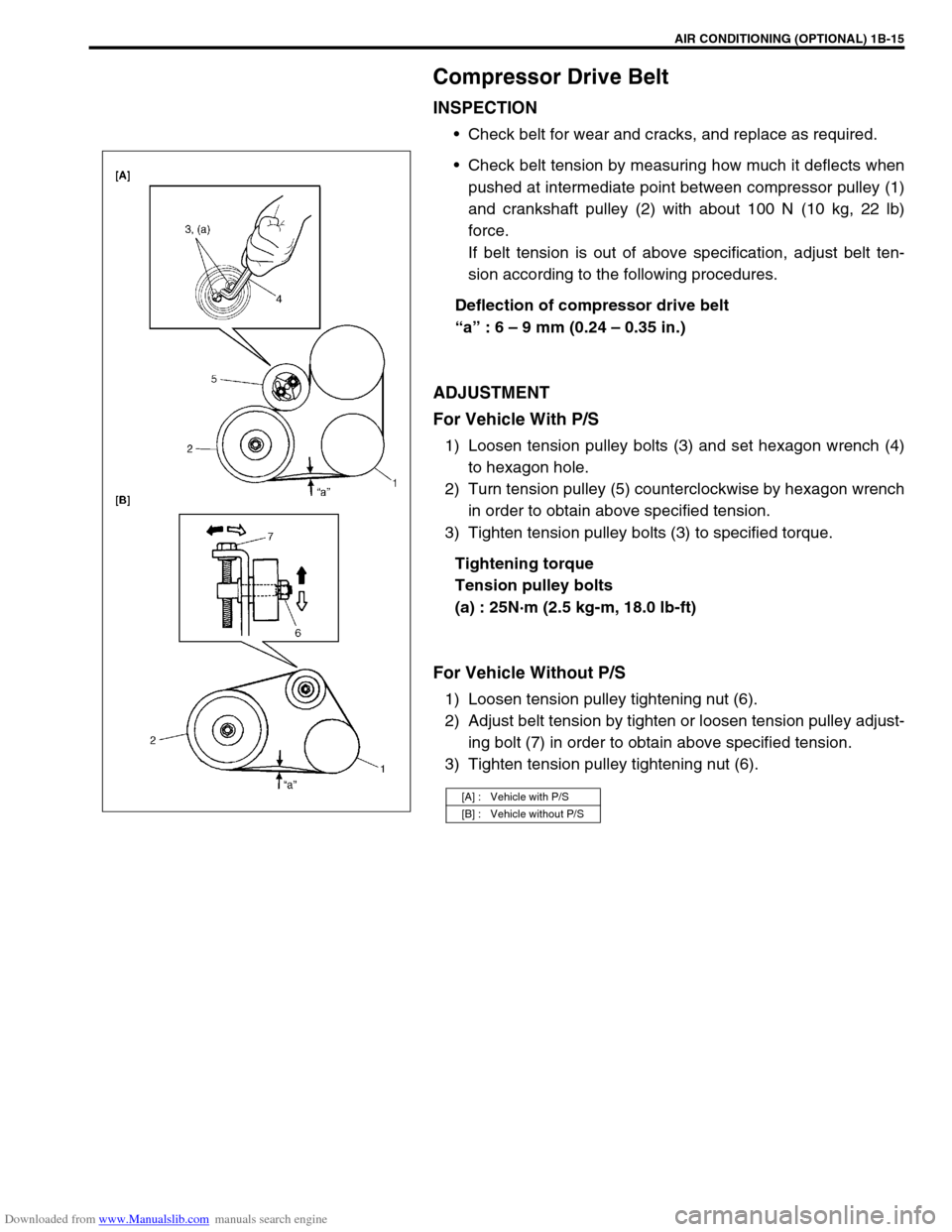
Check belt tension by measuring how much it deflects when
pushed at intermediate point between compressor pulley (1)
and crankshaft pulley (2) with about 100 N (10 kg, 22 lb)
force.
If belt tension is out of above specification, adjust belt ten-
sion according to the following procedures.
Deflection of compressor drive belt
“a” : 6 – 9 mm (0.24 – 0.35 in.)
ADJUSTMENT
For Vehicle With P/S
1) Loosen tension pulley bolts (3) and set hexagon wrench (4)
to hexagon hole.
2) Turn tension pulley (5) counterclockwise by hexagon wrench
in order to obtain above specified tension.
3) Tighten tension pulley bolts (3) to specified torque.
Tightening torque
Tension pulley bolts
(a) : 25N·m (2.5 kg-m, 18.0 lb-ft)
For Vehicle Without P/S
1) Loosen tension pulley tightening nut (6).
2) Adjust belt tension by tighten or loosen tension pulley adjust-
ing bolt (7) in order to obtain above specified tension.
3) Tighten tension pulley tightening nut (6).
[A] : Vehicle with P/S
[B] : Vehicle without P/S
Page 80 of 687

Downloaded from www.Manualslib.com manuals search engine AIR CONDITIONING (OPTIONAL) 1B-19
ECM VOLTAGE VALUES TABLE FOR RELATION OF A/C CONTROL
Terminal Wire CircuitMeasurement
groundNormal value Condition
E18-1 PCompressor
magnet clutch
outputGround to
engine (Fig B)10 – 14 voltBlower fan motor switch and A/C
switch ON with engine running
0 – 1 voltsExcept the above-mentioned condi-
tion with engine running
E18-5 Bl/BMain power sup-
ply for ECMGround to
engine (Fig B)10 – 14 voltsIgnition switch ON with engine
stopped
E18-6 Bl/BMain power sup-
ply for ECMGround to
engine (Fig B)10 – 14 voltsIgnition switch ON with engine
stopped
E18-10 Bl Main relay driveGround to
engine (Fig B)0.5 – 1.2 voltIgnition switch ON with engine
stopped
0 volts Ignition switch OFF
E18-16 G/W A/C switch inputGround to
engine (Fig B)12 – 15 voltsBlower fan motor switch or A/C switch
OFF with engine running
0 – 1 voltBlower fan motor switch and A/C
switch ON with engine running
12 – 15 voltsWithin several seconds after operate
transfer lever between 2WD and 4WD
with above condition
E18-18 P/BCompressor
cooling fan relay
outputGround to
engine (Fig B)0 – 1 voltBlower fan motor switch and A/C
switch ON or engine coolant tempera-
ture at more than 110 °C (230 °F) with
engine running.
12 – 15 voltsExcept the above-mentioned condi-
tion with engine running
E18-20 B/BlSensor ground
for A/C evapora-
torGround to
body (Fig A)–0.5 – 0 volt Engine running
E18-24 Bl/YBlower fan
speed inputGround to
engine (Fig B)0 – 1 voltBlower fan motor switch 2nd or 3rd
with engine running
4 – 7 voltsBlower fan motor switch 1st with
engine running
12 – 15 voltsBlower fan motor switch and A/C
switch OFF with engine running
E19-1 BMain ground for
ECMGround to
engine (Fig A)–0.5 – 1 volt Engine running
E19-2 B/RECM ground for
power circuitGround to
engine (Fig A)–0.5 – 1 volt Engine running
E19-3 B/RECM ground for
power circuitGround to
engine (Fig A)–0.5 – 1 volt Engine running
E19-10 B/BlSensor ground
for ECT sensorGround to
body (Fig A)–0.5 – 1 volt Engine running
Page 92 of 687

Downloaded from www.Manualslib.com manuals search engine AIR CONDITIONING (OPTIONAL) 1B-31
Condenser Assembly
INSPECTION
Check the following.
Check clog of condenser fins.
If, any clogs are found, condenser fins should be washed
with water, and should be dried with compressed air.
Check condenser fins for leakage and breakage.
If any defects are found, repair or replace condenser.
Check condenser fittings for leakage.
If any defects are found, repair or replace condenser.
REMOVAL
1) Disconnect negative (–) cable at battery.
2) Recover refrigerant from A/C system by referring to “Recov-
ery” in this section.
3) Remove front bumper referring to “Front Bumper” in Section
8.
4) Disconnect A/C condenser cooling fan motor and dual pres-
sure switch connectors.
5) Remove radiator mounting bolts.
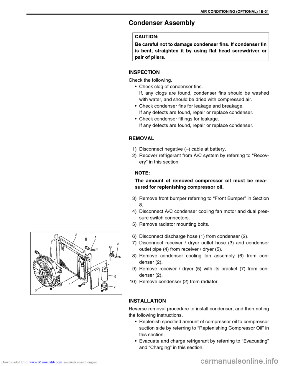
6) Disconnect discharge hose (1) from condenser (2).
7) Disconnect receiver / dryer outlet hose (3) and condenser
outlet pipe (4) from receiver / dryer (5).
8) Remove condenser cooling fan assembly (6) from con-
denser (2).
9) Remove receiver / dryer (5) with its bracket (7) from con-
denser (2).
10) Remove condenser (2) from radiator.
INSTALLATION
Reverse removal procedure to install condenser, and then noting
the following instructions.
Replenish specified amount of compressor oil to compressor
suction side by referring to “Replenishing Compressor Oil” in
this section.
Evacuate and charge refrigerant by referring to “Evacuating”
and “Charging” in this section. CAUTION:
Be careful not to damage condenser fins. If condenser fin
is bent, straighten it by using flat head screwdriver or
pair of pliers.
NOTE:
The amount of removed compressor oil must be mea-
sured for replenishing compressor oil.
Page 94 of 687

Downloaded from www.Manualslib.com manuals search engine AIR CONDITIONING (OPTIONAL) 1B-33
Condenser Cooling Fan Assembly
ASSEMBLY
INSPECTION
1) Check continuity between each two terminals about the con-
denser cooling fan motor (1).
If check results are no continuity, replace condenser cooling
fan motor.
2) Connect battery to condenser cooling fan motor as shown in
figure, then check that the condenser cooling fan motor
operates smoothly.
Reference current of condenser cooling fan motor
approximately 7.5 A at 12 V
REMOVAL
1) Remove front bumper.
2) Disconnect condenser cooling fan motor connector (1).
3) Remove radiator mounting bolts.
4) Remove condenser cooling fan assembly (2) from con-
denser (3).
INSTALLATION
Reverse removal procedure for installation.CAUTION:
Be careful not to damage condenser fins. If condenser fin
is bent, straighten condenser fin by using flat head
screwdriver or pair of pliers.
Page 95 of 687

Downloaded from www.Manualslib.com manuals search engine 1B-34 AIR CONDITIONING (OPTIONAL)
Cooling Unit (Evaporator)
REMOVAL
1) Disconnect negative (–) cable at battery.
2) Recover refrigerant from A/C system by referring to “Recov-
ery” in this section. CAUTION:
Be careful not to damage A/C evaporator fins. If A/C evaporator fin is bent, straighten A/C evaporator
fin by using flat head screwdriver or pair of pliers.
1. A/C evaporator 3. Expansion valve 5. Packing 7. O-ring
2. A/C evaporator thermistor
(A/C evaporator temperature sensor)4. Evaporator case 6. Air inlet door 8. Door link
NOTE:
The amount of removed compressor oil must be mea-
sured for replenishing compressor oil.