Page 250 of 687
Downloaded from www.Manualslib.com manuals search engine WHEELS AND TIRES 3F-7
Lower than Recommended Pressure Can Cause:
1) Tire squeal on turns
2) Hard steering
3) Rapid and uneven wear on the edges of the tread
4) Tire rim bruises and rupture
5) Tire cord breakage
6) High tire temperatures
7) Reduced handling
8) High fuel consumption
Tire placard
The tire placard is located on the driver’s side door lock pillar and should be referred to for tire information. The
placard lists the maximum load, tire size and cold tire pressure where applicable.
Tire rotation
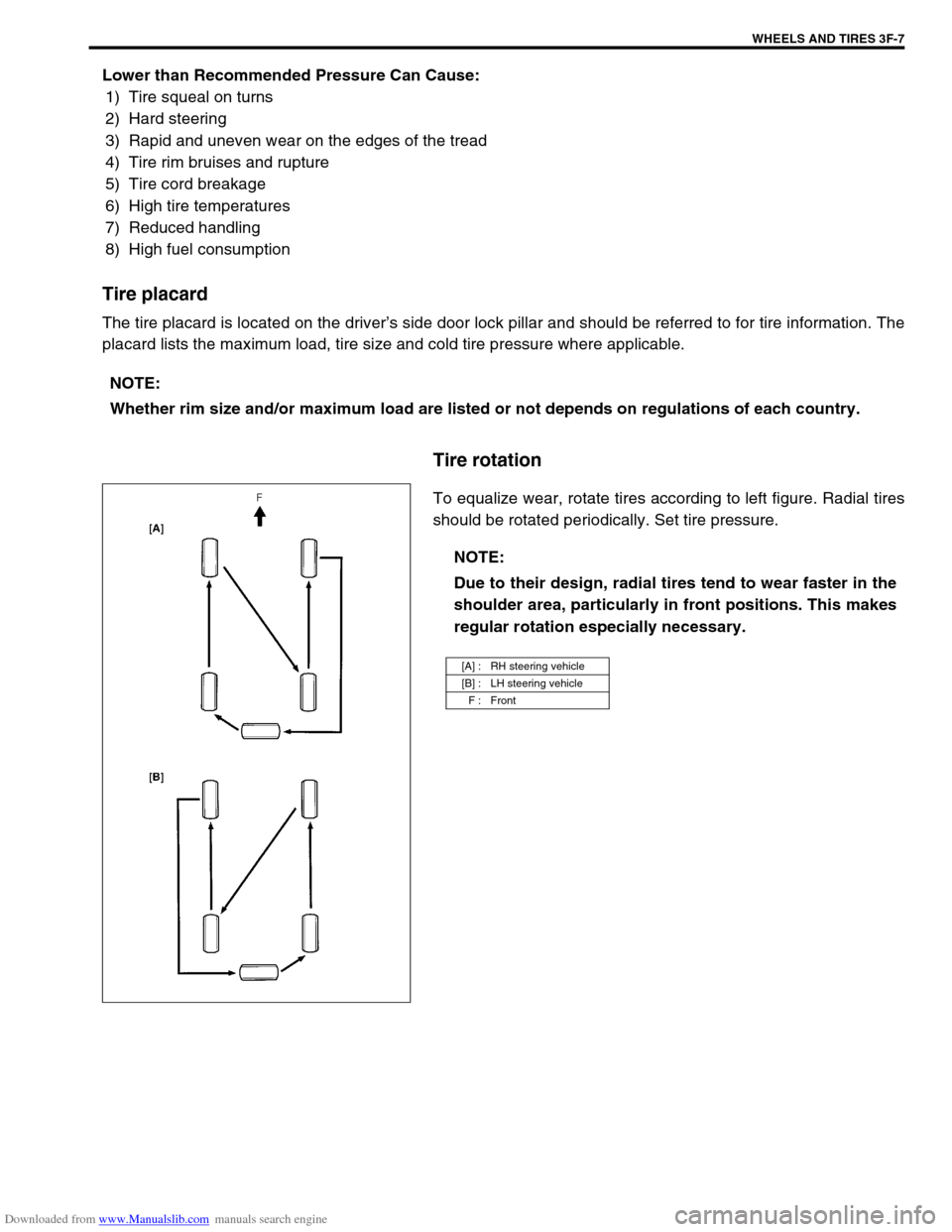
To equalize wear, rotate tires according to left figure. Radial tires
should be rotated periodically. Set tire pressure. NOTE:
Whether rim size and/or maximum load are listed or not depends on regulations of each country.
NOTE:
Due to their design, radial tires tend to wear faster in the
shoulder area, particularly in front positions. This makes
regular rotation especially necessary.
[A] : RH steering vehicle
[B] : LH steering vehicle
F : Front
Page 255 of 687
Downloaded from www.Manualslib.com manuals search engine 4B-2 PROPELLER SHAFTS
General Description
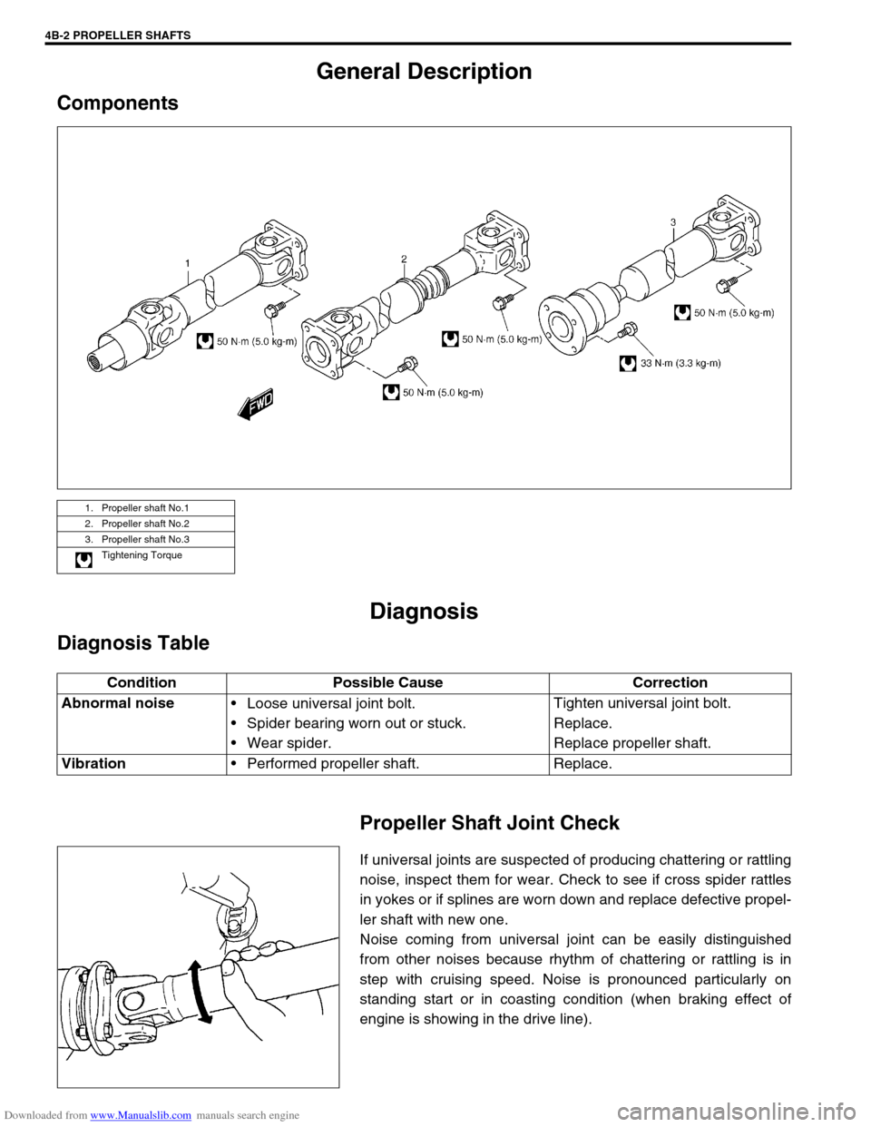
Components
Diagnosis
Diagnosis Table
Propeller Shaft Joint Check
If universal joints are suspected of producing chattering or rattling
noise, inspect them for wear. Check to see if cross spider rattles
in yokes or if splines are worn down and replace defective propel-
ler shaft with new one.
Noise coming from universal joint can be easily distinguished
from other noises because rhythm of chattering or rattling is in
step with cruising speed. Noise is pronounced particularly on
standing start or in coasting condition (when braking effect of
engine is showing in the drive line).
1. Propeller shaft No.1
2. Propeller shaft No.2
3. Propeller shaft No.3
Tightening Torque
Condition Possible Cause Correction
Abnormal noise
Loose universal joint bolt.
Spider bearing worn out or stuck.
Wear spider.Tighten universal joint bolt.
Replace.
Replace propeller shaft.
Vibration
Performed propeller shaft. Replace.
Page 265 of 687

Downloaded from www.Manualslib.com manuals search engine 5-4 BRAKES
Diagnosis
Road Testing Brakes
Brakes should be tested on dry, clean, smooth and reasonably level roadway which is not crowned. Road test
brakes by making brake applications with both light and heavy pedal forces at various speeds to determine if the
vehicle stops evenly and effectively.
Also drive vehicle to see if it leads to one side or the other without brake application. If it does, check the tire
pressure, front end alignment and front suspension attachments for looseness. See diagnosis table for other
causes.
Brake Fluid Leaks
Check the master cylinder fluid levels. While a slight drop in reservoir level does result from normal lining wear,
an abnormally low level indicates a leak in the system. In such a case, check the entire brake system for leak-
age. If even a slight evidence of leakage is noted, the cause should be corrected or defective parts should be
replaced.
If fluid level is lower than the minimum level of reservoir, refilling is necessary. Fill reservoir with specified brake
fluid.
Brake fluid: Refer to reservoir tank cap.
Substandard or Contaminated Brake Fluid
Improper brake fluid, mineral oil or water in the fluid may cause the brake fluid to boil or the rubber components
in the hydraulic system to deteriorate.
If primary piston cups are swollen, then rubber parts have deteriorated. This deterioration may also be evi-
denced by swollen wheel cylinder piston cups on the drum brake wheels.
If deterioration of rubber is evident, disassemble all hydraulic parts and wash with alcohol. Dry these parts with
compressed air before assembly to keep alcohol out of the system. Replace all rubber parts in the system,
including hoses. Also, when working on the brake mechanisms, check for fluid on the linings. If excessive fluid is
found, replace the linings.
If master cylinder piston seals are satisfactory, check for leakage or excessive heat conditions. If condition is not
found, drain fluid, flush with brake fluid, refill and bleed the system.
The system must be flushed if there is any doubt as to the grade of fluid in the system or if fluid has been used
which contained parts that have been subjected to contaminated fluid.CAUTION:
Since brake system of this vehicle is factory-filled with brake fluid indicated on reservoir tank cap, do
not use or mix different type of fluid when refilling; otherwise serious damage will occur.
Do not use old or used brake fluid, or any fluid from a unsealed container.
Page 276 of 687
Downloaded from www.Manualslib.com manuals search engine BRAKES 5-15
Fluid Pressure Test (If Equipped with LSPV)
Test procedure for LSPV assembly is as follows.
Before testing, confirm the following.
Fuel tank is filled with fuel fully.
Vehicle is equipped with spare tire, tools, jack and jack han-
dle.
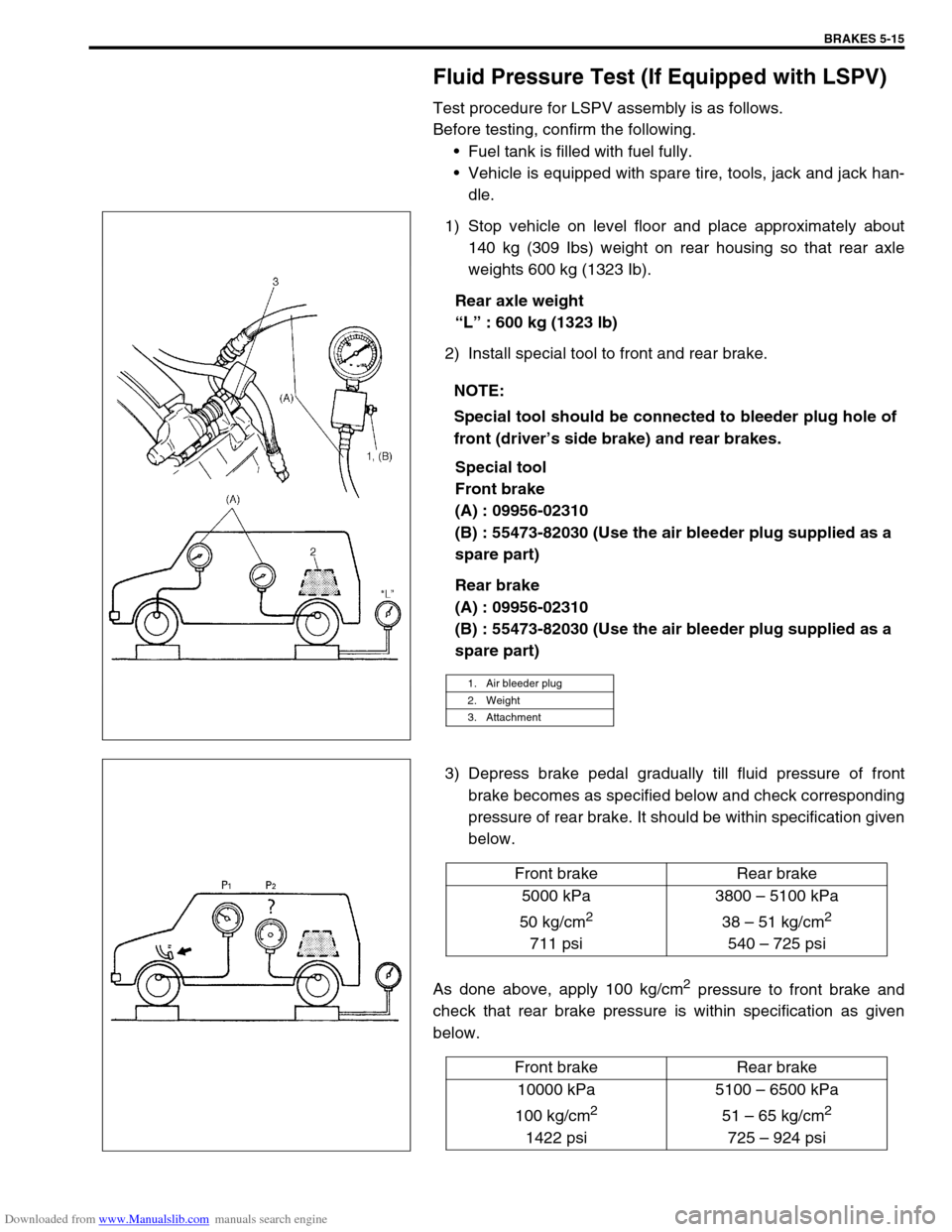
1) Stop vehicle on level floor and place approximately about
140 kg (309 Ibs) weight on rear housing so that rear axle
weights 600 kg (1323 Ib).
Rear axle weight
“L” : 600 kg (1323 lb)
2) Install special tool to front and rear brake.
Special tool
Front brake
(A) : 09956-02310
(B) : 55473-82030 (Use the air bleeder plug supplied as a
spare part)
Rear brake
(A) : 09956-02310
(B) : 55473-82030 (Use the air bleeder plug supplied as a
spare part)
3) Depress brake pedal gradually till fluid pressure of front
brake becomes as specified below and check corresponding
pressure of rear brake. It should be within specification given
below.
As done above, apply 100 kg/cm
2 pressure to front brake and
check that rear brake pressure is within specification as given
below.NOTE:
Special tool should be connected to bleeder plug hole of
front (driver’s side brake) and rear brakes.
1. Air bleeder plug
2. Weight
3. Attachment
Front brake Rear brake
5000 kPa
50 kg/cm
2
711 psi3800 – 5100 kPa
38 – 51 kg/cm
2
540 – 725 psi
Front brake Rear brake
10000 kPa
100 kg/cm
2
1422 psi5100 – 6500 kPa
51 – 65 kg/cm
2
725 – 924 psi
Page 291 of 687
Downloaded from www.Manualslib.com manuals search engine 5-30 BRAKES
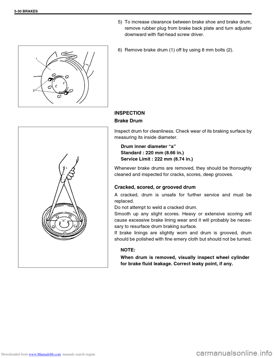
5) To increase clearance between brake shoe and brake drum,
remove rubber plug from brake back plate and turn adjuster
downward with flat-head screw driver.
6) Remove brake drum (1) off by using 8 mm bolts (2).
INSPECTION
Brake Drum
Inspect drum for cleanliness. Check wear of its braking surface by
measuring its inside diameter.
Drum inner diameter “a”
Standard : 220 mm (8.66 in.)
Service Limit : 222 mm (8.74 in.)
Whenever brake drums are removed, they should be thoroughly
cleaned and inspected for cracks, scores, deep grooves.
Cracked, scored, or grooved drum
A cracked, drum is unsafe for further service and must be
replaced.
Do not attempt to weld a cracked drum.
Smooth up any slight scores. Heavy or extensive scoring will
cause excessive brake lining wear and it will probably be neces-
sary to resurface drum braking surface.
If brake linings are slightly worn and drum is grooved, drum
should be polished with fine emery cloth but should not be turned.
NOTE:
When drum is removed, visually inspect wheel cylinder
for brake fluid leakage. Correct leaky point, if any.
Page 298 of 687
Downloaded from www.Manualslib.com manuals search engine BRAKES 5-37
INSTALLATION
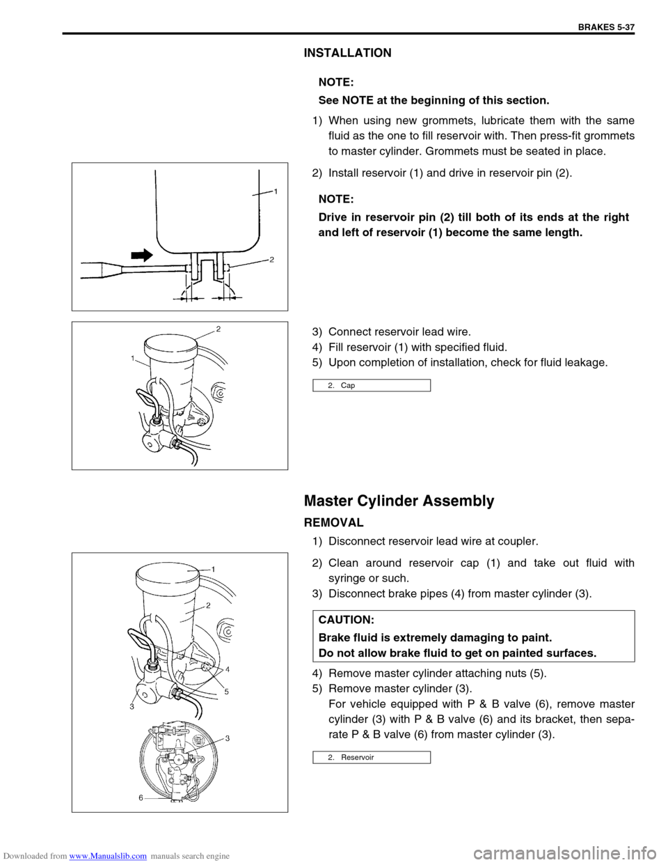
1) When using new grommets, lubricate them with the same
fluid as the one to fill reservoir with. Then press-fit grommets
to master cylinder. Grommets must be seated in place.
2) Install reservoir (1) and drive in reservoir pin (2).
3) Connect reservoir lead wire.
4) Fill reservoir (1) with specified fluid.
5) Upon completion of installation, check for fluid leakage.
Master Cylinder Assembly
REMOVAL
1) Disconnect reservoir lead wire at coupler.
2) Clean around reservoir cap (1) and take out fluid with
syringe or such.
3) Disconnect brake pipes (4) from master cylinder (3).
4) Remove master cylinder attaching nuts (5).
5) Remove master cylinder (3).
For vehicle equipped with P & B valve (6), remove master
cylinder (3) with P & B valve (6) and its bracket, then sepa-
rate P & B valve (6) from master cylinder (3). NOTE:
See NOTE at the beginning of this section.
NOTE:
Drive in reservoir pin (2) till both of its ends at the right
and left of reservoir (1) become the same length.
2. Cap
CAUTION:
Brake fluid is extremely damaging to paint.
Do not allow brake fluid to get on painted surfaces.
2. Reservoir
Page 308 of 687
Downloaded from www.Manualslib.com manuals search engine BRAKES 5-47
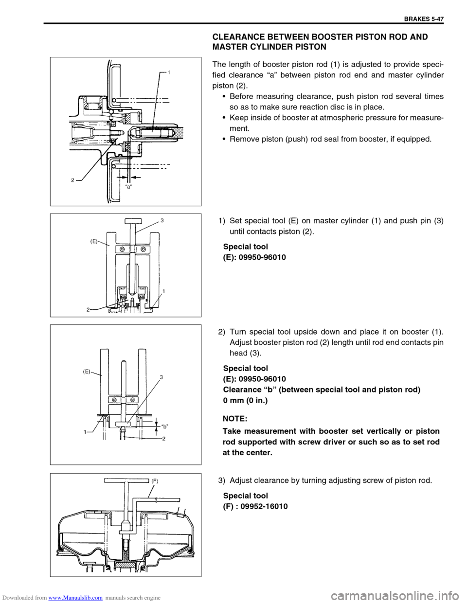
CLEARANCE BETWEEN BOOSTER PISTON ROD AND
MASTER CYLINDER PISTON
The length of booster piston rod (1) is adjusted to provide speci-
fied clearance “a” between piston rod end and master cylinder
piston (2).
Before measuring clearance, push piston rod several times
so as to make sure reaction disc is in place.
Keep inside of booster at atmospheric pressure for measure-
ment.
Remove piston (push) rod seal from booster, if equipped.
1) Set special tool (E) on master cylinder (1) and push pin (3)
until contacts piston (2).
Special tool
(E): 09950-96010
2) Turn special tool upside down and place it on booster (1).
Adjust booster piston rod (2) length until rod end contacts pin
head (3).
Special tool
(E): 09950-96010
Clearance “b” (between special tool and piston rod)
0 mm (0 in.)
3) Adjust clearance by turning adjusting screw of piston rod.
Special tool
(F) : 09952-16010
NOTE:
Take measurement with booster set vertically or piston
rod supported with screw driver or such so as to set rod
at the center.
Page 320 of 687

Downloaded from www.Manualslib.com manuals search engine ANTILOCK BRAKE SYSTEM (ABS) 5E-3
System Schematic
1. Wheel speed sensor (Right front) 7. Wheel speed sensor (Left rear) 13. ABS hydraulic unit
2. Stop lamp switch 8.“ABS” warning lamp 14. G sensor
3. ABS control module 9. ABS pump motor transistor 15. Data link connector
4. Wheel speed sensor (Right rear) 10. ABS solenoid valve transistor 16. ABS hydraulic unit / control module assembly
5. Monitor connector 11. Proportioning valve 17. 4WD switch (for 4WD model only)
6. ABS lamp driver module 12. Wheel speed sensor (Left front)
INPUTOUTPUT
ABS control
module Wheel speed sensor (RF)
Wheel speed sensor (RR)
Wheel speed sensor (LR)
Wheel speed sensor (LF)
Stop lamp switch
Diag. switch terminal
Battery voltage
4WD switch (for 4WD model only) G sensor
Pump motor
transistor
Fail-safe
transistor
Pump motor
LF hold solenoid
LF release solenoid
RF hold solenoid
RF release solenoid
Rear hold solenoid
Rear release solenoid
“ABS” warning lamp
Idle-up
ECM
Data link connector
ABS hydraulic unit/control
module assembly