2005 SUZUKI JIMNY piston
[x] Cancel search: pistonPage 307 of 687

Downloaded from www.Manualslib.com manuals search engine 5-46 BRAKES
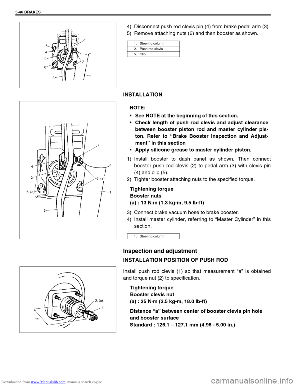
4) Disconnect push rod clevis pin (4) from brake pedal arm (3).
5) Remove attaching nuts (6) and then booster as shown.
INSTALLATION
1) Install booster to dash panel as shown, Then connect
booster push rod clevis (2) to pedal arm (3) with clevis pin
(4) and clip (5).
2) Tighter booster attaching nuts to the specified torque.
Tightening torque
Booster nuts
(a) : 13 N·m (1.3 kg-m, 9.5 Ib-ft)
3) Connect brake vacuum hose to brake booster.
4) Install master cylinder, referring to “Master Cylinder” in this
section.
Inspection and adjustment
INSTALLATION POSITION OF PUSH ROD
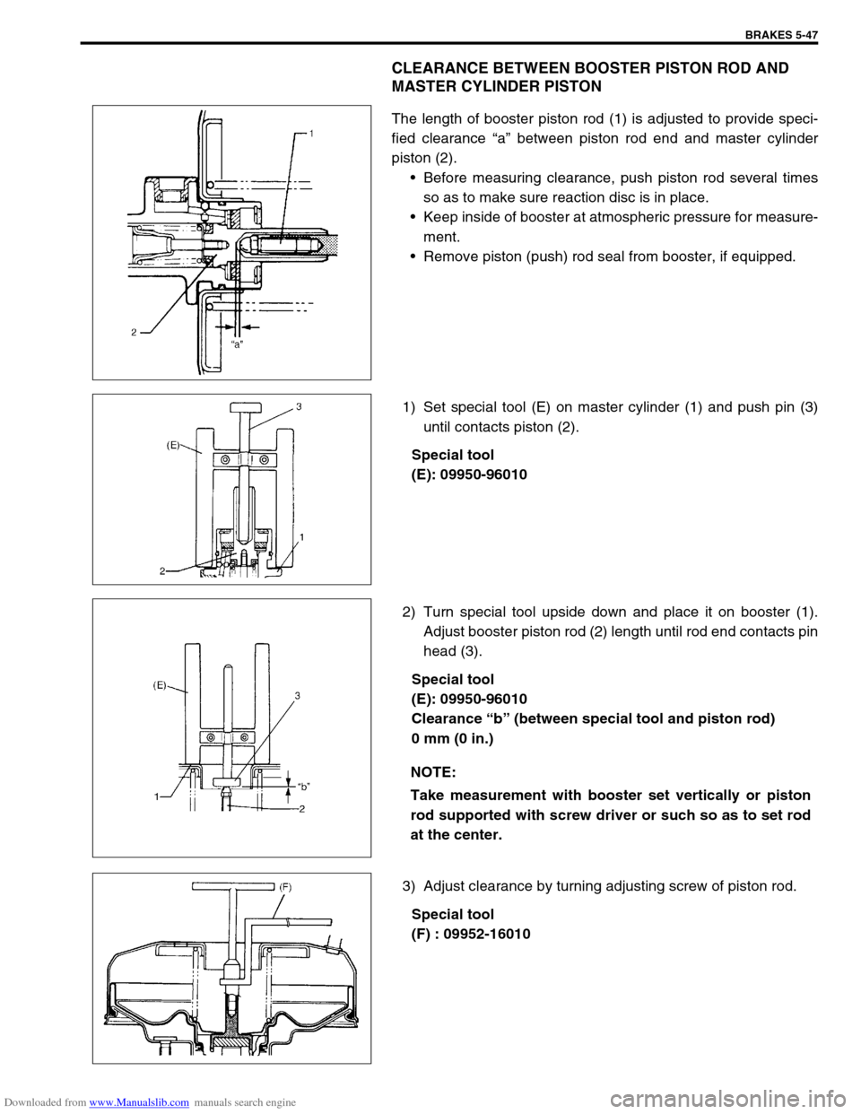
Install push rod clevis (1) so that measurement “a” is obtained
and torque nut (2) to specification.
Tightening torque
Booster clevis nut
(a) : 25 N·m (2.5 kg-m, 18.0 Ib-ft)
Distance “a” between center of booster clevis pin hole
and booster surface
Standard : 126.1 – 127.1 mm (4.96 - 5.00 in.)
1. Steering column
2. Push rod clevis
5. Clip
NOTE:
See NOTE at the beginning of this section.
Check length of push rod clevis and adjust clearance
between booster piston rod and master cylinder pis-
ton. Refer to “Brake Booster Inspection and Adjust-
ment” in this section
Apply silicone grease to master cylinder piston.
1. Steering column
Page 308 of 687

Downloaded from www.Manualslib.com manuals search engine BRAKES 5-47
CLEARANCE BETWEEN BOOSTER PISTON ROD AND
MASTER CYLINDER PISTON
The length of booster piston rod (1) is adjusted to provide speci-
fied clearance “a” between piston rod end and master cylinder
piston (2).
Before measuring clearance, push piston rod several times
so as to make sure reaction disc is in place.
Keep inside of booster at atmospheric pressure for measure-
ment.
Remove piston (push) rod seal from booster, if equipped.
1) Set special tool (E) on master cylinder (1) and push pin (3)
until contacts piston (2).
Special tool
(E): 09950-96010
2) Turn special tool upside down and place it on booster (1).
Adjust booster piston rod (2) length until rod end contacts pin
head (3).
Special tool
(E): 09950-96010
Clearance “b” (between special tool and piston rod)
0 mm (0 in.)
3) Adjust clearance by turning adjusting screw of piston rod.
Special tool
(F) : 09952-16010
NOTE:
Take measurement with booster set vertically or piston
rod supported with screw driver or such so as to set rod
at the center.
Page 315 of 687

Downloaded from www.Manualslib.com manuals search engine 5-54 BRAKES
Tightening Torque Specifications
Required Service Material
Fastening partTightening torque
Nm kg-m lb-ft
Brake caliper carrier bolt 85 8.5 61.5
Brake caliper pin bolt 22 2.2 16.0
Front brake flexible hose bolt 23 2.3 17.0
Rear brake back plate nut 23 2.3 17.0
Master cylinder nut 13 1.3 9.5
Booster nut 13 1.3 9.5
Brake pipe 5-way 4-way joint bolt 11 1.1 8.0
Brake pipe flare nut 16 1.6 12.0
LSPV bolt/P valve bolt 25 2.5 18.0
Brake bleeder plugFront caliper 11 1.1 8.0
Rear wheel cylinder, LSPV 8 0.8 6.0
Wheel nut 95 9.5 69.0
Hose bracket bolt 11 1.1 8.0
Booster clevis nut 25 2.5 18.0
Stop light switch lock nut 6.5 0.65 4.7
Parking brake lever bolt 23 2.3 17.0
Wheel cylinder mounting bolt 9 0.9 6.5
Piston stopper bolt 10 1.0 7.5
LSPV adjust bolt 25 2.5 18.0
Material Recommended SUZUKI products Use
Brake fluid Indicated on reservoir tank cap or
described in owner’s manual of vehi-
cleTo fill master cylinder reservoir.
To clean and apply to inner parts of master
cylinder caliper and wheel cylinder when they
are disassembled.
Water tight sealant SEALING COMPOUND 366E
99000-31090To apply to mating surfaces of brake back
plate and rear wheel cylinder.
Sealant SUZUKI BOND NO. 1215
99000-31110To apply to mating surfaces of brake back
plate and rear axle housing.
To apply to mating surfaces of brake back
plate and rear wheel bearing retainer.
Page 316 of 687

Downloaded from www.Manualslib.com manuals search engine BRAKES 5-55
Special Tool
09900-20205 09900-20602 09900-20701 09956-02210
Micrometer (0 – 25 mm) Dial gauge (1/1000 mm) Magnetic stand Brake circuit plug
09922-85811 09942-15510 09943-35511 09950-78220
Connector pin remover Sliding hammer Brake drum remover
(Front wheel hub
remover)Flare nut wrench (10 mm)
09950-96010 09952-16010 09956-02310
Booster piston rod gauge Booster piston rod
adjusterFluid pressure gauge
Page 360 of 687

Downloaded from www.Manualslib.com manuals search engine ENGINE GENERAL INFORMATION AND DIAGNOSIS 6-3
General Information
Statement on Cleanliness and Care
An automobile engine is a combination of many machined, honed, polished and lapped surfaces with tolerances
that are measured in the thousands of an millimeter (ten thousands of an inch).
Accordingly, when any internal engine parts are serviced, care and cleanliness are important.
Throughout this section, it should be understood that proper cleaning and protection of machined surfaces and
friction areas is part of the repair procedure. This is considered standard shop practice even if not specifically
stated.
A liberal coating of engine oil should be applied to friction areas during assembly to protect and lubricate the
surfaces on initial operation.
Whenever valve train components, pistons, piston rings, connecting rods, rod bearings, and crankshaft jour-
nal bearings are removed for service, they should be retained in order.
At the time of installation, they should be installed in the same locations and with the same mating surfaces
as when removed.
Battery cables should be disconnected before any major work is performed on the engine.
Failure to disconnect cables may result in damage to wire harness or other electrical parts.
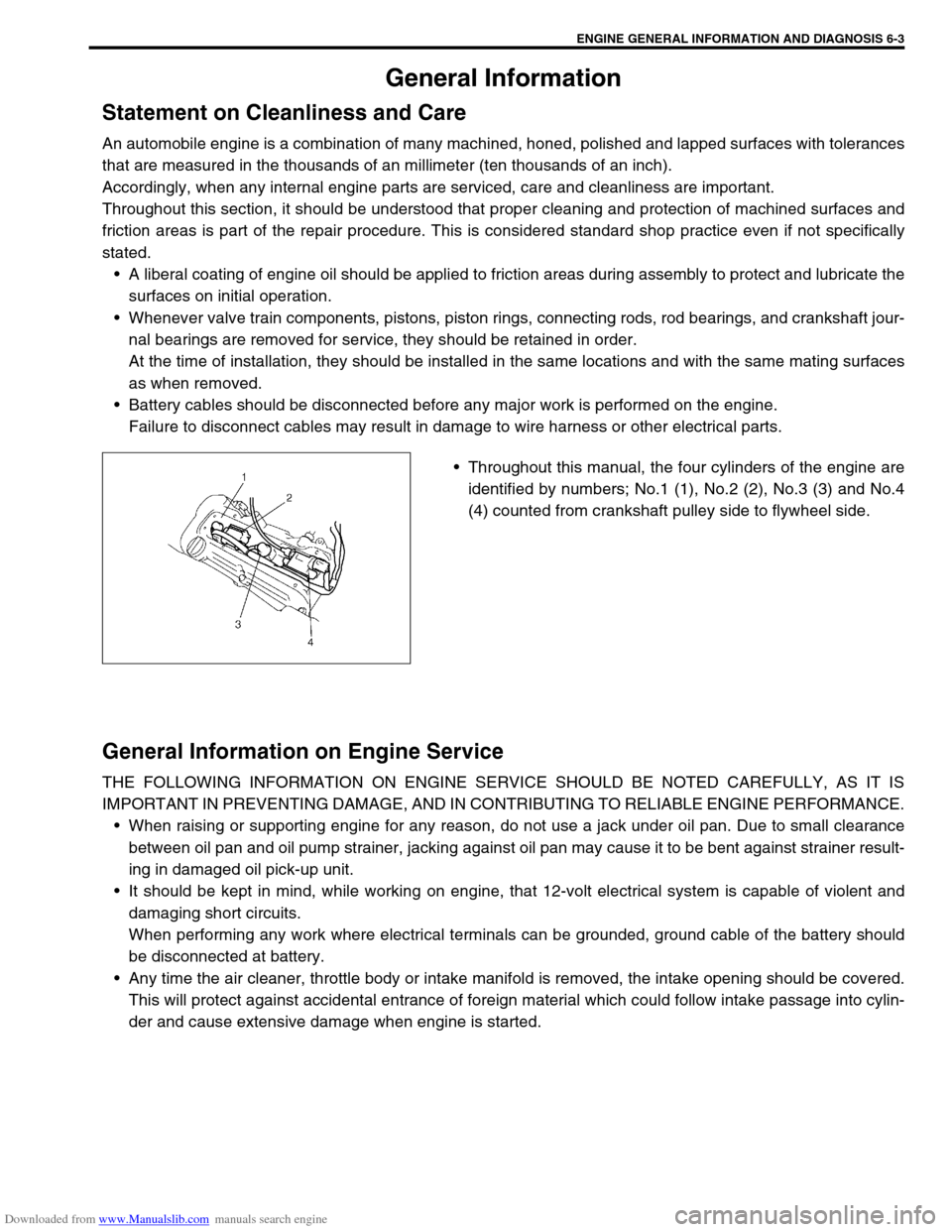
Throughout this manual, the four cylinders of the engine are
identified by numbers; No.1 (1), No.2 (2), No.3 (3) and No.4
(4) counted from crankshaft pulley side to flywheel side.
General Information on Engine Service
THE FOLLOWING INFORMATION ON ENGINE SERVICE SHOULD BE NOTED CAREFULLY, AS IT IS
IMPORTANT IN PREVENTING DAMAGE, AND IN CONTRIBUTING TO RELIABLE ENGINE PERFORMANCE.
When raising or supporting engine for any reason, do not use a jack under oil pan. Due to small clearance
between oil pan and oil pump strainer, jacking against oil pan may cause it to be bent against strainer result-
ing in damaged oil pick-up unit.
It should be kept in mind, while working on engine, that 12-volt electrical system is capable of violent and
damaging short circuits.
When performing any work where electrical terminals can be grounded, ground cable of the battery should
be disconnected at battery.
Any time the air cleaner, throttle body or intake manifold is removed, the intake opening should be covered.
This will protect against accidental entrance of foreign material which could follow intake passage into cylin-
der and cause extensive damage when engine is started.
Page 380 of 687
![SUZUKI JIMNY 2005 3.G Service Workshop Manual Downloaded from www.Manualslib.com manuals search engine ENGINE GENERAL INFORMATION AND DIAGNOSIS 6-23
[D] Fig. 4 for Step 7 or 8 / [E] Fig. 5 for Step 10 / [F] Fig. 6 for Step 13
Engine diagnosis tab SUZUKI JIMNY 2005 3.G Service Workshop Manual Downloaded from www.Manualslib.com manuals search engine ENGINE GENERAL INFORMATION AND DIAGNOSIS 6-23
[D] Fig. 4 for Step 7 or 8 / [E] Fig. 5 for Step 10 / [F] Fig. 6 for Step 13
Engine diagnosis tab](/manual-img/20/7588/w960_7588-379.png)
Downloaded from www.Manualslib.com manuals search engine ENGINE GENERAL INFORMATION AND DIAGNOSIS 6-23
[D] Fig. 4 for Step 7 or 8 / [E] Fig. 5 for Step 10 / [F] Fig. 6 for Step 13
Engine diagnosis table
Perform troubleshooting referring to following table when ECM has no DTC and no abnormality found in visual
inspection and engine basic inspection previously.
Condition Possible Cause Reference Item
Hard Starting
(Engine cranks OK)Faulty ignition coil Ignition coil assembly in Section 6F.
Faulty CMP sensing rotor or CKP sensing
rotorCMP sensing rotor or CKP sensing
rotor inspection in Section 6E.
Faulty idle air control system Diagnostic Flow Table B-4
Faulty ECT sensor, TP sensor, CKP sen-
sor, CMP sensor or MAP sensorECT sensor, TP sensor, CKP sensor,
CMP sensor or MAP sensor in Sec-
tion 6E.
Fuel pressure out of specification Diagnostic Flow Table B-3
Faulty fuel injector Diagnostic Flow Table B-1
Faulty ECM Inspection of ECM and its circuit in
this section.
Malfunctioning PCV system PCV system in Section 6E.
Low compression Compression check in Section 6A1.
Improper valve lash Valve lash in Section 6A1.
Improper valve timing Timing chain and chain tensioner in
Section 6A1.
Compression leak from valve seat Valves and cylinder head in Section
6A1.
Sticky valve stem Valves and cylinder head in Section
6A1.
Weak or damaged valve springs Valves and cylinder head in Section
6A1.
Compression leak at cylinder head gasket Valves and cylinder head in Section
6A1.
Sticking or damaged piston ring Pistons, piston rings, connecting rods
and cylinders in Section 6A1.
Worn piston, ring or cylinder Pistons, piston rings, connecting rods
and cylinders in Section 6A1.
Page 382 of 687

Downloaded from www.Manualslib.com manuals search engine ENGINE GENERAL INFORMATION AND DIAGNOSIS 6-25
Excessive detonation
(The engine makes
sharp metallic knocks
that change with throt-
tle opening.
Sounds like pop corn
popping.)Engine overheating Refer to “Overheating” of this table.
Faulty spark plug Spark plugs in Section 6F.
Clogged fuel filter and fuel lines Diagnostic Flow Table B-3
Malfunctioning EGR valve (if equipped) EGR system in Section 6E.
Poor performance of knock sensor, ECT
sensor or MAP sensorKnock sensor in this section, ECT
sensor or MAP sensor in Section 6E.
Faulty injector Diagnostic Flow Table B-1
Faulty ECM Inspection of ECM and its circuit in
this section.
Excessive combustion chamber deposits Piston and cylinder head in Section
6A1.
Overheating
Inoperative thermostat Thermostat in Section 6B.
Faulty A/C condenser fan motor or its cir-
cuitA/C condenser fan control system
check in Section 6E.
Loose or slip water pump belt ITEM1-1 Drive belt inspection and
change in Section 0B.
Poor water pump performance Water pump in Section 6B.
Clogged or leaky radiator Radiator in Section 6B.
Improper engine oil grade ITEM1-3 Engine oil and oil filter
change in Section 0B.
Clogged oil filter or oil strainer Oil pressure check in Section 6A1.
Poor oil pump performance Oil pressure check in Section 6A1.
Dragging brakes Diagnosis Table in Section 5.
Slipping clutch Diagnosis Table in Section 7C.
Blown cylinder head gasket Valves and cylinder head in Section
6A1.
Poor gasoline mileage
Faulty ignition coil Ignition coil assembly in Section 6F.
Fuel pressure out of specification Diagnostic Flow Table B-3
Faulty TP sensor, ECT sensor or MAP
sensorTP sensor, ECT sensor or MAP sen-
sor in Section 6E.
Faulty injector Diagnostic Flow Table B-1
Faulty ECM Inspection of ECM and its circuit in
this section.
Malfunctioning EGR valve (if equipped) EGR system in Section 6E.
High idle speed Refer to item “Improper Engine Idle
Speed” previously outlined.
Low compression Previously outlined.
Poor valve seating Valves and cylinder head in Section
6A1.
Dragging brakes Diagnosis Table in Section 5.
Slipping clutch Diagnosis Table in Section 7C.
Thermostat out of order Thermostat in Section 6B.
Improper tire pressure Refer to Section 3F. Condition Possible Cause Reference Item
Page 383 of 687

Downloaded from www.Manualslib.com manuals search engine 6-26 ENGINE GENERAL INFORMATION AND DIAGNOSIS
Excessive engine oil
consumptionSticky piston ring Pistons, piston rings, connecting rods
and cylinders in Section 6A1.
Worn piston and cylinder Pistons, piston rings, connecting rods
and cylinders in Section 6A1.
Worn piston ring groove and ring Pistons, piston rings, connecting rods
and cylinders in Section 6A1.
Improper location of piston ring gap Pistons, piston rings, connecting rods
and cylinders in Section 6A1.
Worn or damaged valve stem seal Valves and cylinder head in Section
6A1.
Worn valve stem Valves and cylinder head in Section
6A1.
Low oil pressure
Improper oil viscosity ITEM1-3 Engine oil and oil filter
change in Section 0B.
Malfunctioning oil pressure switch Oil pressure switch in Section 8.
Clogged oil strainer Oil pan and oil pump strainer in Sec-
tion 6A1.
Functional deterioration of oil pump Oil pump in Section 6A1.
Worn oil pump relief valve Oil pump in Section 6A1.
Excessive clearance in various sliding
partsRefer to Section 6A1.
Engine noise
See NOTE below.Improper valve lash Valve lash in Section 6A1.
Worn valve stem and guide Valves and cylinder head in Section
6A1.
Weak or broken valve spring Valve springs in Section 6A1.
Warped or bent valve Valves and cylinder head in Section
6A1.
Loose camshaft housing bolts Camshaft in Section 6A1.
Worn piston, ring and cylinder bore Pistons and cylinders in Section 6A1.
Worn crankpin bearing Crankpin and connecting rod bearing
in Section 6A1.
Worn crankpin Crankpin and connecting rod bearing
in Section 6A1.
Loose connecting rod nuts Connecting rod in Section 6A1.
Low oil pressure Previously outlined.
Worn crankshaft journal bearing Main bearings, Crankshaft and cylin-
der block in Section 6A1.
Worn crankshaft journal Main bearings, Crankshaft and cylin-
der block in Section 6A1.
Loose lower crankcase (bearing cap) bolts Main bearings, Crankshaft and cylin-
der block in Section 6A1.
Excessive crankshaft thrust play Main bearings, Crankshaft and cylin-
der block in Section 6A1. Condition Possible Cause Reference Item
NOTE:
Before checking the mechanical noise, make sure that :
Ignition timing is properly adjusted.
Specified spark plug is used.
Specified fuel is used.