2005 SUZUKI JIMNY piston
[x] Cancel search: pistonPage 482 of 687

Downloaded from www.Manualslib.com manuals search engine ENGINE MECHANICAL (M13 ENGINE) 6A1-1
6F1
6G
6H
6K
7A
7A1
7B1
7C1
7D
7E
7F
8A
8C
6A1
8E
9
9
10B
SECTION 6A1
ENGINE MECHANICAL (M13 ENGINE)
CONTENTS
General Description ......................................6A1-2
Engine ......................................................... 6A1-2
Engine Lubrication ...................................... 6A1-3
Diagnosis .......................................................6A1-4
Diagnosis Table .......................................... 6A1-4
Compression Check .................................... 6A1-4
Engine Vacuum Check ................................ 6A1-6
Oil Pressure Check ..................................... 6A1-7
Valve Lash (Clearance) ............................... 6A1-9
On-Vehicle Service......................................6A1-13
Air Cleaner Element .................................. 6A1-13
Air Cleaner Assembly ................................ 6A1-14
Knock Sensor ............................................ 6A1-14
Cylinder Head Cover ................................. 6A1-15
Throttle Body and Intake Manifold ............ 6A1-18
Exhaust Manifold ....................................... 6A1-21Oil Pan and Oil Pump Strainer .................. 6A1-24
Timing Chain Cover .................................. 6A1-28
Oil Pump ................................................... 6A1-33
Timing Chain and Chain Tensioner .......... 6A1-37
Camshaft, Tappet and Shim ..................... 6A1-42
Valves and Cylinder Head ........................ 6A1-48
Pistons, Piston Rings, Connecting
Rods and Cylinders................................... 6A1-62
Engine Mountings ..................................... 6A1-72
Unit Repair Overhaul .................................. 6A1-73
Engine Assembly ...................................... 6A1-73
Main Bearings, Crankshaft and Cylinder
Block ......................................................... 6A1-79
Required Service Material .......................... 6A1-93
Tightening Torque Specification ............... 6A1-93
Special Tool ................................................. 6A1-94
WARNING:
For vehicles equipped with Supplemental Restraint (Air Bag) System:
Service on and around the air bag system components or wiring must be performed only by an
authorized SUZUKI dealer. Refer to “Air Bag System Components and Wiring Location View” under
“General Description” in air bag system section in order to confirm whether you are performing ser-
vice on or near the air bag system components or wiring. Please observe all WARNINGS and “Ser-
vice Precautions” under “On-Vehicle Service” in air bag system section before performing service
on or around the air bag system components or wiring. Failure to follow WARNINGS could result in
unintentional activation of the system or could render the system inoperative. Either of these two
conditions may result in severe injury.
Technical service work must be started at least 90 seconds after the ignition switch is turned to the
“LOCK” position and the negative cable is disconnected from the battery. Otherwise, the system
may be activated by reserve energy in the Sensing and Diagnostic Module (SDM).
Page 484 of 687

Downloaded from www.Manualslib.com manuals search engine ENGINE MECHANICAL (M13 ENGINE) 6A1-3
Engine Lubrication
The oil pump is of a trochoid type, and mounted under the crankshaft. Oil is drawn up through the oil pump
strainer and passed through the pump to the oil filter.
The filtered oil flows into 2 paths in cylinder block.
In one path, oil reaches the crankshaft journal bearings. Oil from the crankshaft journal bearings is supplied to
the connecting rod bearings by means of intersecting passages drilled in the crankshaft, and then injected from
the big end of connecting rod to lubricate piston, rings, and cylinder wall.
In other path oil goes up to the cylinder head and lubricates valves and camshafts, etc., after passing through
the internal oilway of camshafts.
An oil relief valve is provided on the oil pump. This valve starts relieving oil pressure when the pressure exceeds
about 400 kPa (4.0 kg/cm
2, 56.9 psi).
Page 518 of 687

Downloaded from www.Manualslib.com manuals search engine ENGINE MECHANICAL (M13 ENGINE) 6A1-37
Timing Chain and Chain Tensioner
REMOVAL
1) Remove timing chain cover referring to “Timing Chain
Cover”.
2) Align both intake and exhaust camshaft timing sprocket
marks (1) with notches (2) of cylinder head respectively by
turning crankshaft.
3) Remove timing chain tensioner adjuster assembly (3).
4) Remove timing chain tensioner (4).
5) Remove timing chain No.1 guide (5).
6) Remove timing chain (6) with crankshaft timing sprocket (7).
1. Crankshaft timing sprocket 5. Timing chain tensioner adjuster assembly Tightening torque
2. Timing chain 6. Chain tensioner adjuster mounting bolt Apply engine oil to sliding surface.
3. Timing chain No.1 guide 7. Chain tensioner mounting bolt
4. Timing chain tensioner 8. Chain guide mounting bolt
CAUTION:
After timing chain is removed, never turn crankshaft and
camshafts independently more than its allowable turning
range described in “INSTALLATION” section.
If turned, interference may occur between piston and
valves and valves themselves, and parts related to piston
and valves may be damaged.
45
6
21
1
3
7
Page 520 of 687

Downloaded from www.Manualslib.com manuals search engine ENGINE MECHANICAL (M13 ENGINE) 6A1-39
INSTALLATION
1) Check that match marks (1) on intake and exhaust camshaft
timing sprockets are in match with notches (2) on cylinder
head as shown in figure.
2) Set key (3) and turn crankshaft to position key on upside of
crankshaft.
3) Install timing chain by aligning dark blue plate (1) of timing
chain and mark (2) on camshaft timing sprocket and then
aligning dark blue plate (3) and triangle mark (4) as shown in
figure.
4) Fit crankshaft timing sprocket to timing chain by aligning gold
plate (5) of timing chain and mark (6) on crankshaft timing
sprocket. Then install crankshaft timing sprocket fitted with
chain to crankshaft.
5) Apply engine oil to sliding surface of timing chain No.1 guide
(1) and install it as shown in figure.
Tighten guide bolts to specified torque.
Tightening torque
Timing chain No.1 guide bolts
(a) : 9 N·m (0.9 kg-m, 6.5 lb-ft) CAUTION:
After timing chain is removed, never turn crankshaft and
camshafts independently more than such an extent (“a”,
“b”) as shown in figure.
If turned, interference may occur between piston and
valves and valves themselves, and parts related to piston
and valves may be damaged.
“a” :90°5. Crankshaft allowable turning range.
By key on crankshaft, within 90° from top on both right and left.
“b” :15°4. Camshaft (IN and EX) allowable turning range.
By marks on camshaft timing sprocket within 15° from notches on
cylinder head on both right and left.
Page 537 of 687

Downloaded from www.Manualslib.com manuals search engine 6A1-56 ENGINE MECHANICAL (M13 ENGINE)
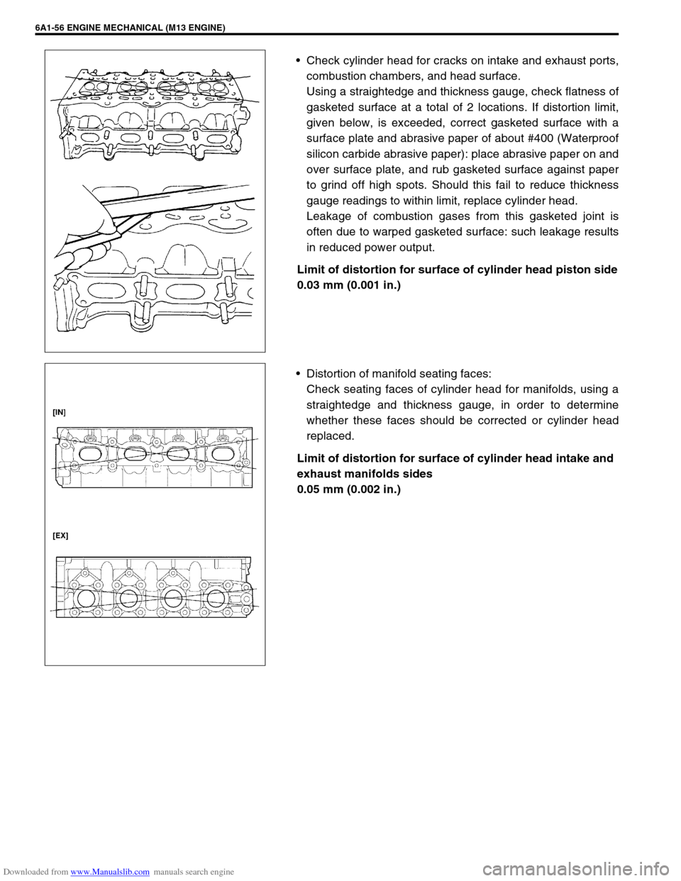
Check cylinder head for cracks on intake and exhaust ports,
combustion chambers, and head surface.
Using a straightedge and thickness gauge, check flatness of
gasketed surface at a total of 2 locations. If distortion limit,
given below, is exceeded, correct gasketed surface with a
surface plate and abrasive paper of about #400 (Waterproof
silicon carbide abrasive paper): place abrasive paper on and
over surface plate, and rub gasketed surface against paper
to grind off high spots. Should this fail to reduce thickness
gauge readings to within limit, replace cylinder head.
Leakage of combustion gases from this gasketed joint is
often due to warped gasketed surface: such leakage results
in reduced power output.
Limit of distortion for surface of cylinder head piston side
0.03 mm (0.001 in.)
Distortion of manifold seating faces:
Check seating faces of cylinder head for manifolds, using a
straightedge and thickness gauge, in order to determine
whether these faces should be corrected or cylinder head
replaced.
Limit of distortion for surface of cylinder head intake and
exhaust manifolds sides
0.05 mm (0.002 in.)
Page 543 of 687

Downloaded from www.Manualslib.com manuals search engine 6A1-62 ENGINE MECHANICAL (M13 ENGINE)
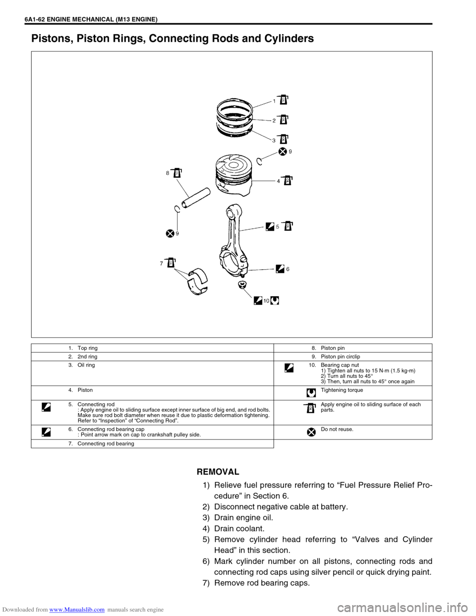
Pistons, Piston Rings, Connecting Rods and Cylinders
REMOVAL
1) Relieve fuel pressure referring to “Fuel Pressure Relief Pro-
cedure” in Section 6.
2) Disconnect negative cable at battery.
3) Drain engine oil.
4) Drain coolant.
5) Remove cylinder head referring to “Valves and Cylinder
Head” in this section.
6) Mark cylinder number on all pistons, connecting rods and
connecting rod caps using silver pencil or quick drying paint.
7) Remove rod bearing caps.
1. Top ring8. Piston pin
2. 2nd ring9. Piston pin circlip
3. Oil ring10. Bearing cap nut
1) Tighten all nuts to 15 N·m (1.5 kg-m)
2) Turn all nuts to 45°
3) Then, turn all nuts to 45° once again
4. PistonTightening torque
5. Connecting rod
: Apply engine oil to sliding surface except inner surface of big end, and rod bolts.
Make sure rod bolt diameter when reuse it due to plastic deformation tightening.
Refer to “Inspection” of “Connecting Rod”.Apply engine oil to sliding surface of each
parts.
6. Connecting rod bearing cap
: Point arrow mark on cap to crankshaft pulley side.Do not reuse.
7. Connecting rod bearing
Page 544 of 687

Downloaded from www.Manualslib.com manuals search engine ENGINE MECHANICAL (M13 ENGINE) 6A1-63
8) Install guide hose (1) over threads of rod bolts.
This prevents damage to bearing journal and rod bolt
threads when removing connecting rod.
9) Decarbon top of cylinder bore before removing piston from
cylinder.
10) Push piston and connecting rod assembly out through the
top of cylinder bore.
DISASSEMBLY
1) Using piston ring expander, remove two compression rings
(Top and 2nd) and oil ring from piston.
2) Remove piston pin from connecting rod.
Ease out piston pin circlips (1), as shown.
Force piston pin out.
CLEANING
Decarbon piston head and ring grooves, using a suitable tool.
INSPECTION
Cylinder
Inspect cylinder walls for scratches, roughness or ridges
which indicate excessive wear. If cylinder bore is very rough
or deeply scratched or ridged, rebore cylinder and use over-
size piston.
Page 545 of 687

Downloaded from www.Manualslib.com manuals search engine 6A1-64 ENGINE MECHANICAL (M13 ENGINE)
Using a cylinder gauge (1), measure cylinder bore in thrust
and axial directions at two positions (“a” and “b”) as shown in
figure.
If any of the following conditions is noted, rebore cylinder.
1) Cylinder bore dia. exceeds limit.
2) Difference of measurements at two positions exceeds taper
limit.
3) Difference between thrust and axial measurements exceeds
out-of-round limit.
Limit on cylinder bore diameter
78.114 mm (3.073 in.)
Limit on taper and out-of-round for cylinder
0.10 mm (0.004 in.)
Pistons
Inspect piston for faults, cracks or other damaged.
Damaged or faulty piston should be replaced.
Piston diameter:
As indicated in figure, piston diameter should be measured
at a position 19.5 mm (0.77 in.) from piston skirt end in the
direction perpendicular to piston pin.
Piston diameter specification NOTE:
If any one of four cylinders has to be rebored, rebore all
four to the same next oversize. This is necessary for the
sake of uniformity and balance.
“a” : 50 mm (1.96 in.)
“b” : 95 mm (3.74 in.)
Standard size77.953 – 77.968 mm
(3.0690 – 3.0696 in.)
Oversize
0.50 mm (0.0196 in.)78.453 – 78.468 mm
(3.0887 – 3.0893 in.)
“a” : 19.5 mm (0.77 in.)