2005 SUZUKI JIMNY load capacity
[x] Cancel search: load capacityPage 15 of 687

Downloaded from www.Manualslib.com manuals search engine 0A-10 GENERAL INFORMATION
Precautions For Catalytic Converter
For vehicles equipped with a catalytic converter, use only unleaded gasoline and be careful not to let a
large amount of unburned gasoline enter the converter or it can be damaged.
Conduct a spark jump test only when necessary, make it as short as possible, and do not open the
throttle.
Conduct engine compression checks within the shortest possible time.
Avoid situations which can result in engine misfire (e.g. starting the engine when the fuel tank is
nearly empty.)
Precautions For Electrical Circuit Service
When replacing a fuse, make sure to use a fuse of the
specified capacity. Use of a fuse with a larger capacity
will cause a damage to the electrical parts and a fire.
When disconnecting and connecting coupler, make sure
to turn ignition switch OFF, or electronic parts may get
damaged.
When disconnecting connectors, never pull the wiring
harnesses. Unlock the connector lock first and then pull
them apart by holding connectors themselves.
Page 39 of 687

Downloaded from www.Manualslib.com manuals search engine 0B-8 MAINTENANCE AND LUBRICATION
6) Replenish oil until oil level is brought to FULL level mark on
dipstick. (oil pan and oil filter capacity). The filler inlet is at
the top of the cylinder head cover.
It is recommended to use engine oil of SE, SF, SG, SH, SJ or
SL grade.
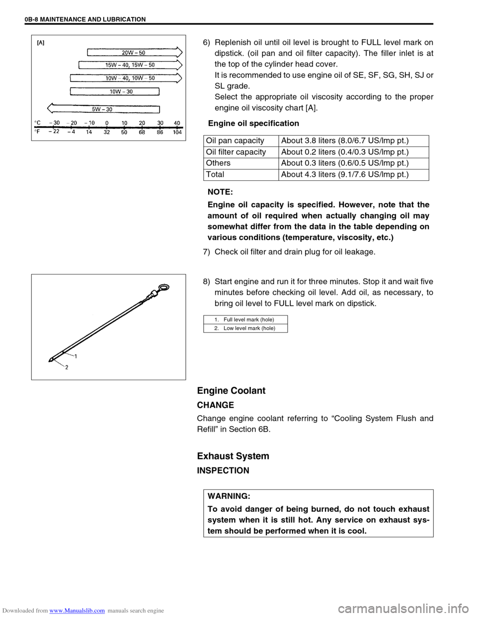
Select the appropriate oil viscosity according to the proper
engine oil viscosity chart [A].
Engine oil specification
7) Check oil filter and drain plug for oil leakage.
8) Start engine and run it for three minutes. Stop it and wait five
minutes before checking oil level. Add oil, as necessary, to
bring oil level to FULL level mark on dipstick.
Engine Coolant
CHANGE
Change engine coolant referring to “Cooling System Flush and
Refill” in Section 6B.
Exhaust System
INSPECTION
Oil pan capacity About 3.8 liters (8.0/6.7 US/lmp pt.)
Oil filter capacity About 0.2 liters (0.4/0.3 US/lmp pt.)
Others About 0.3 liters (0.6/0.5 US/lmp pt.)
Total About 4.3 liters (9.1/7.6 US/lmp pt.)
NOTE:
Engine oil capacity is specified. However, note that the
amount of oil required when actually changing oil may
somewhat differ from the data in the table depending on
various conditions (temperature, viscosity, etc.)
1. Full level mark (hole)
2. Low level mark (hole)
WARNING:
To avoid danger of being burned, do not touch exhaust
system when it is still hot. Any service on exhaust sys-
tem should be performed when it is cool.
Page 70 of 687

Downloaded from www.Manualslib.com manuals search engine AIR CONDITIONING (OPTIONAL) 1B-9
Quick Checking of Refrigerant Charge
The following procedure can be used for quickly checking whether
the A/C system has a proper charge of refrigerant or not.
Run engine at fast idle, and operate A/C at its maximum cooling
capacity for a few minutes. Then, look at the sight glass (1) on
receiver / dryer (2) and compare what is observed with the symp-
toms listed in below.
CHECKING REFRIGERANT CHARGE
3. Bubbles
Symptom Charge of refrigerant condition Correction
Bubbles observed in sight glass Insufficient charge of refrigerant in
systemCheck system for leaks with a
leak tester.
No bubbles observed in sight glass No or insufficient charge of refrig-
erant in systemRefer to the items 3 and 4.
No temperature difference between
compressor inlet and outletEmpty or nearly empty system Evacuate and charge system and
then check it for leaks with a leak
tester.
Noticeable temperature difference
between compressor inlet and outletProper or too much charge of
refrigerant in systemRefer to the items 5 and 6.
When A/C is turned OFF, refrigerant in
sight glass clears immediately and
remains clearToo much charge of refrigerant in
systemDischarge excess refrigerant in
order to obtain a specified charge.
When A/C is turned OFF, refrigerant in
sight glass once produces bubbles and
then clearsProper charge of refrigerant in
systemNo correction needed because
charge of refrigerant is normal.
Page 245 of 687

Downloaded from www.Manualslib.com manuals search engine 3F-2 WHEELS AND TIRES
General Description
Tires
This vehicle is equipped with following tire.
Tire size
: 205/70 R15 or 175/80 R15
The tires are of tubeless type. The tires are designed to operate satisfactorily with loads up to the full rated load
capacity when inflated to the recommended inflation pressure.
Correct tire pressures and driving habits have an important influence on tire life Heavy cornering, excessively
rapid acceleration, and unnecessary sharp braking increase tire wear.
Wheels
Standard equipment wheels are following steel wheels.
15 x 5 1/2 JJ
Replacement Tires
When replacement is necessary, the original equipment type tire should be used. Refer to the Tire Placard.
Replacement tires should be of the same size, load range and construction as those originally on the vehicle.
Use of any other size or type tire may affect ride, handling, speedometer / odometer calibration, vehicle ground
clearance and tire or snow chain clearance to the body and chassis.
It is recommended that new tires be installed in pairs on the same axle. If necessary to replace only one tire, it
should be paired with the tire having the most tread, to equalize braking traction.
The metric term for tire inflation pressure is the kilopascal (kPa).
Tire pressures will usually be printed in both kPa and psi on the
Tire Placard. Metric tire gauges are available from tool suppliers.
The following chart, converts commonly used inflation pressures
from kPa to psi. WARNING:
Do not mix different types of tires on the same vehicle such as radial, bias and bias-belted tires except
in emergencies, because vehicle handling may be seriously affected and may result in loss of control.
kPa
kgf/cm2psi
160
180
200
220
240
260
280
300
320
3401.6
1.8
2.0
2.2
2.4
2.6
2.8
3.0
3.2
3.423
26
29
32
35
38
41
44
47
50
Page 246 of 687

Downloaded from www.Manualslib.com manuals search engine WHEELS AND TIRES 3F-3
Replacement Wheels
Wheels must be replaced if they are bent, dented, have excessive
lateral or radial runout, leak air through welds, have elongated
bolt holes, if lug nuts won’t stay tight, or if they are heavily rusted.
Wheels with greater runout than shown in “How to Measure
Wheel Runout” may cause objectional vibrations.
Wheels for replacement must be equivalent to the originally
equipped wheels in load capacity, diameter, rim width, off-set and
mounting configuration. A wheel of improper size or type may
affect wheel and bearing life, brake cooling, speedometer / odom-
eter calibration, ground clearance to the body and chassis.
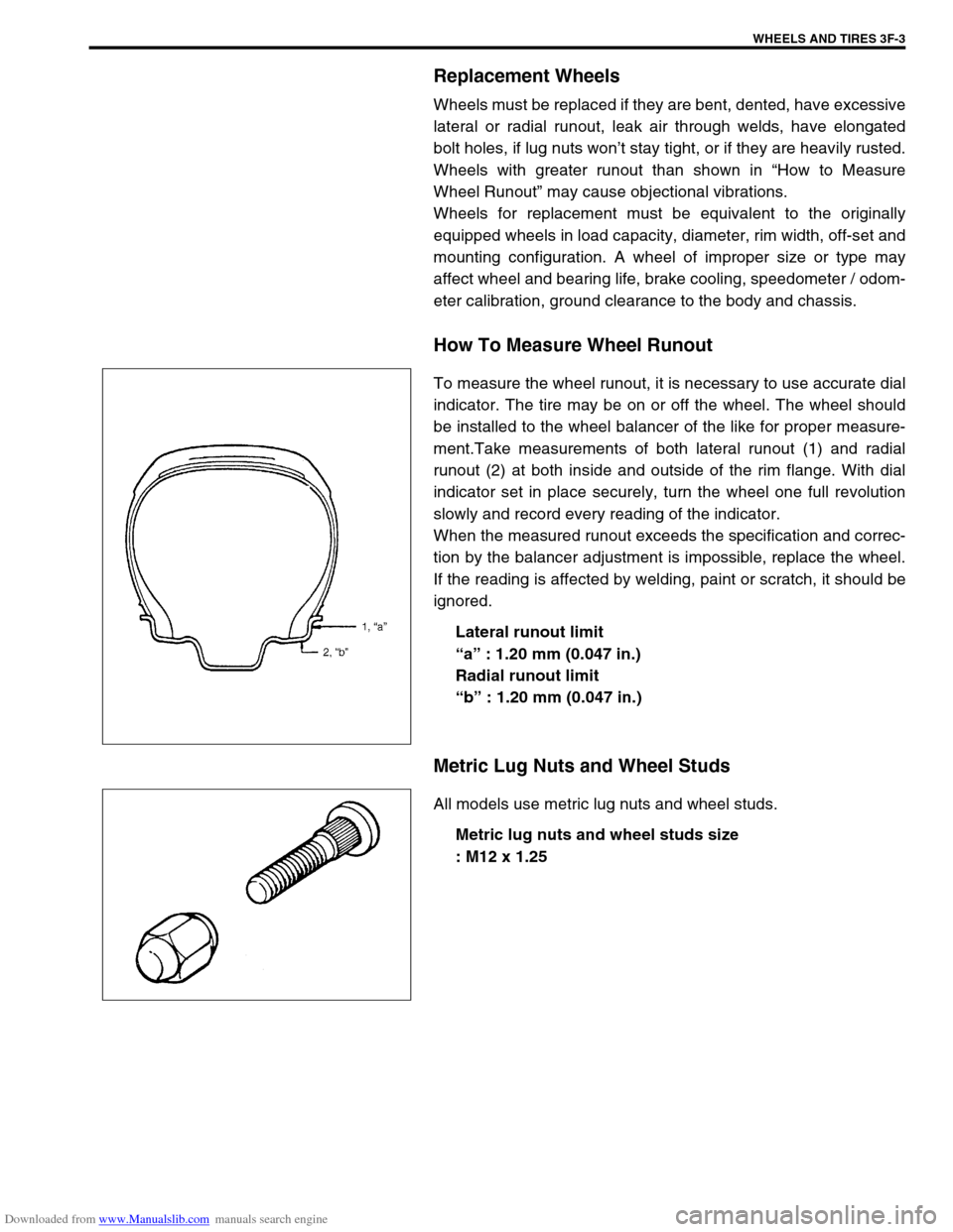
How To Measure Wheel Runout
To measure the wheel runout, it is necessary to use accurate dial
indicator. The tire may be on or off the wheel. The wheel should
be installed to the wheel balancer of the like for proper measure-
ment.Take measurements of both lateral runout (1) and radial
runout (2) at both inside and outside of the rim flange. With dial
indicator set in place securely, turn the wheel one full revolution
slowly and record every reading of the indicator.
When the measured runout exceeds the specification and correc-
tion by the balancer adjustment is impossible, replace the wheel.
If the reading is affected by welding, paint or scratch, it should be
ignored.
Lateral runout limit
“a” : 1.20 mm (0.047 in.)
Radial runout limit
“b” : 1.20 mm (0.047 in.)
Metric Lug Nuts and Wheel Studs
All models use metric lug nuts and wheel studs.
Metric lug nuts and wheel studs size
: M12 x 1.25
Page 389 of 687

Downloaded from www.Manualslib.com manuals search engine 6-32 ENGINE GENERAL INFORMATION AND DIAGNOSIS
FUEL TANK LEVEL (%)
This parameter indicates approximate fuel level in the fuel tank. As the detectable range of the fuel level sensor
is set as 0 to 100%, however, with some models whose fuel tank capacity is smaller, the indicated fuel level may
be only 70% even when the fuel tank is full.
PNP SIGNAL (PARK / NEUTRAL POSITION SIGNAL, P/N RANGE or D RANGE)
It is detected by signal from TCM.
D range : A/T is in “R”, “D”, “2” or “L” range.
P/N range : A/T is in “P” or “N” range or the above signal is not inputted from TCM.
EGR VALVE (%)
This parameter indicates opening rate of EGR valve which controls the amount of EGR flow.
PSP SW
The Power Steering Pressure switch parameter displays ON when steering wheel is turned all the way to the
right or left.
Page 583 of 687

Downloaded from www.Manualslib.com manuals search engine 6B-6 ENGINE COOLING
Maintenance
Coolant
The coolant recovery system is standard. The coolant in the radiator expands with heat, and the overflow is col-
lected in the reservoir.
When the system cools down, the coolant is drawn back into the radiator.
The cooling system has been filled at the factory with a quality coolant that is either 50/50 mixture of water and
anti-freeze / anti-corrosion coolant (ethylene glycol antifreeze).
The 50/50 mixture coolant solution provides freezing protection to – 36 °C ( – 33 °F).
Maintain cooling system freeze protection at – 36 °C ( – 33 °F) to ensure protection against corrosion and
loss of coolant from boiling.
This should be done even if freezing temperatures are not expected.
Add ethylene glycol base coolant when coolant has to be added because of coolant loss or to provide added
protection against freezing at temperature lower than – 36 °C ( – 33 °F).
Anti-freeze proportioning table
Coolant capacity Freezing temperature°C– 16– 36
°F3– 33
Anti-freeze / Anti-corrosion
coolant concentration%30 50
Ratio of compound
to cooling waterItr. 1.35/3.15 2.25/2.25
US pt. 2.85/6.65 4.75/4.75
Imp pt. 2.37/5.53 3.95/3.95
Engine radiator and heater 5.2 liters (11.0/9.2 US/lmp. pt.)
Reservoir 0.7 liters (1.5/1.2 US/lmp. pt.)
Total 5.9 liters (12.5/10.5 US/lmp. pt.)
NOTE:
Alcohol or methanol base coolant or plain water alone should not be used in cooling system at any
time as damage to cooling system could occur.
Even in a market where no freezing temperature is anticipated, mixture of 70% water and 30% ethyl-
ene glycol antifreeze (Antifreeze / Anticorrosion coolant) should be used for the purpose of corro-
sion protection and lubrication.
Page 584 of 687

Downloaded from www.Manualslib.com manuals search engine ENGINE COOLING 6B-7
Coolant Level
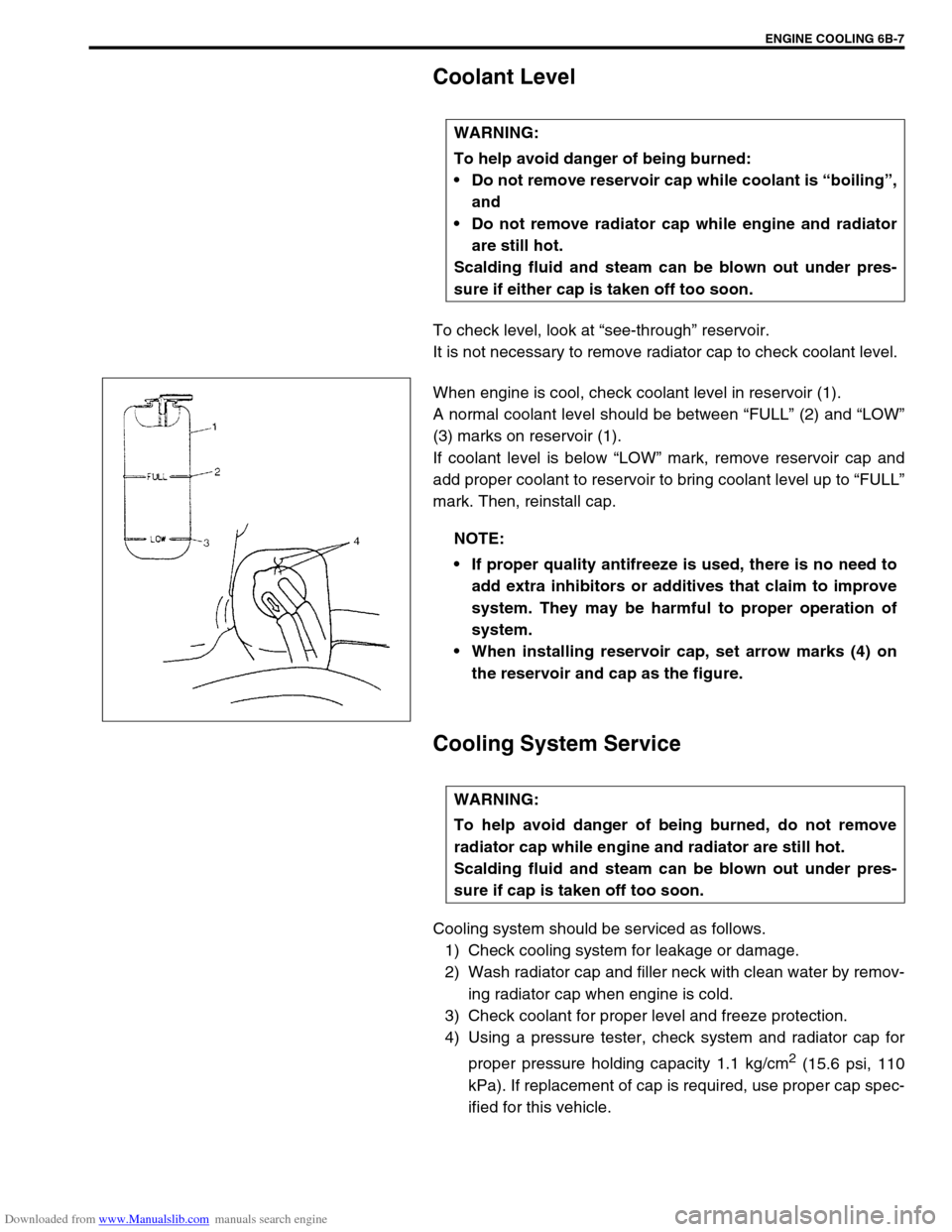
To check level, look at “see-through” reservoir.
It is not necessary to remove radiator cap to check coolant level.
When engine is cool, check coolant level in reservoir (1).
A normal coolant level should be between “FULL” (2) and “LOW”
(3) marks on reservoir (1).
If coolant level is below “LOW” mark, remove reservoir cap and
add proper coolant to reservoir to bring coolant level up to “FULL”
mark. Then, reinstall cap.
Cooling System Service
Cooling system should be serviced as follows.
1) Check cooling system for leakage or damage.
2) Wash radiator cap and filler neck with clean water by remov-
ing radiator cap when engine is cold.
3) Check coolant for proper level and freeze protection.
4) Using a pressure tester, check system and radiator cap for
proper pressure holding capacity 1.1 kg/cm
2 (15.6 psi, 110
kPa). If replacement of cap is required, use proper cap spec-
ified for this vehicle. WARNING:
To help avoid danger of being burned:
Do not remove reservoir cap while coolant is “boiling”,
and
Do not remove radiator cap while engine and radiator
are still hot.
Scalding fluid and steam can be blown out under pres-
sure if either cap is taken off too soon.
NOTE:
If proper quality antifreeze is used, there is no need to
add extra inhibitors or additives that claim to improve
system. They may be harmful to proper operation of
system.
When installing reservoir cap, set arrow marks (4) on
the reservoir and cap as the figure.
WARNING:
To help avoid danger of being burned, do not remove
radiator cap while engine and radiator are still hot.
Scalding fluid and steam can be blown out under pres-
sure if cap is taken off too soon.