2005 SUZUKI JIMNY cyl head
[x] Cancel search: cyl headPage 39 of 687

Downloaded from www.Manualslib.com manuals search engine 0B-8 MAINTENANCE AND LUBRICATION
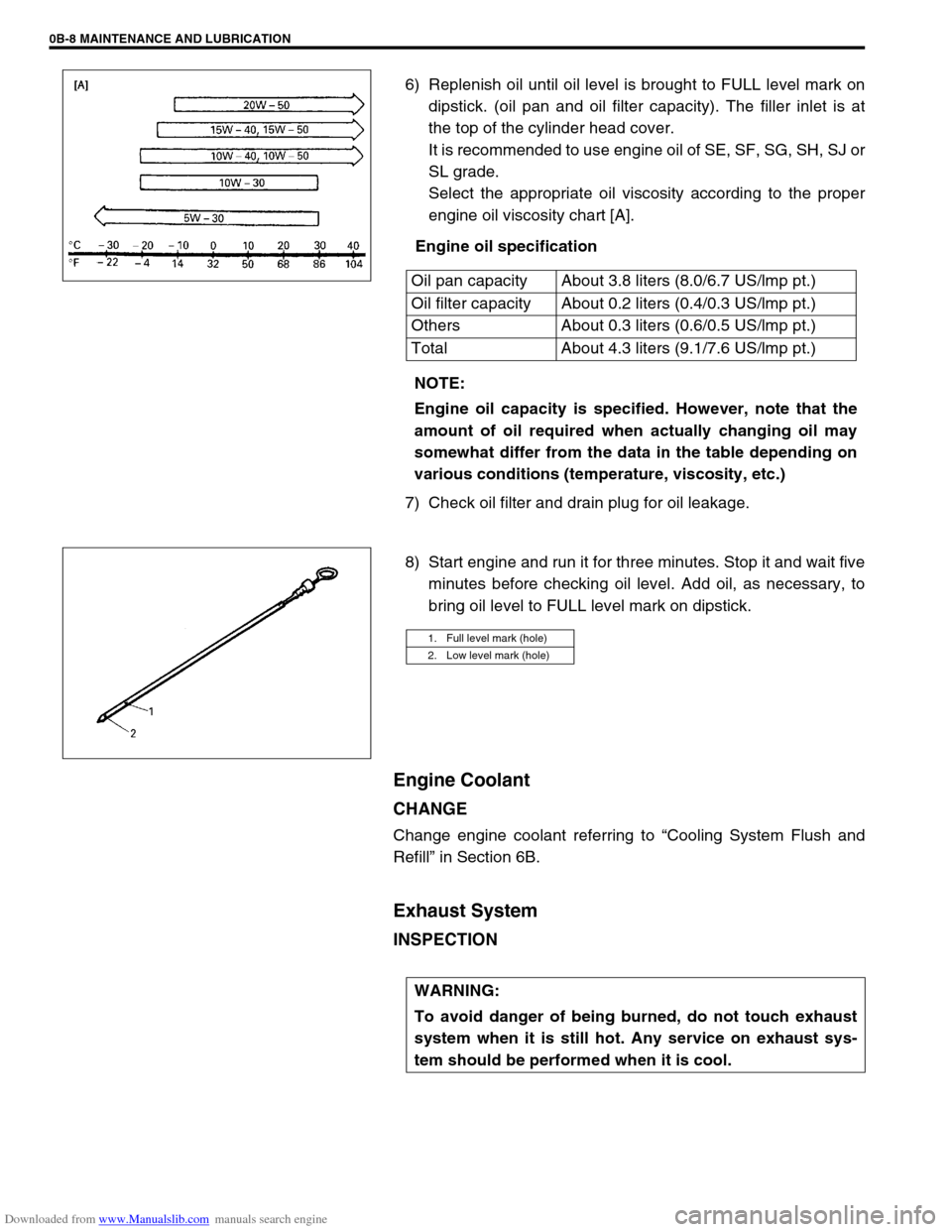
6) Replenish oil until oil level is brought to FULL level mark on
dipstick. (oil pan and oil filter capacity). The filler inlet is at
the top of the cylinder head cover.
It is recommended to use engine oil of SE, SF, SG, SH, SJ or
SL grade.
Select the appropriate oil viscosity according to the proper
engine oil viscosity chart [A].
Engine oil specification
7) Check oil filter and drain plug for oil leakage.
8) Start engine and run it for three minutes. Stop it and wait five
minutes before checking oil level. Add oil, as necessary, to
bring oil level to FULL level mark on dipstick.
Engine Coolant
CHANGE
Change engine coolant referring to “Cooling System Flush and
Refill” in Section 6B.
Exhaust System
INSPECTION
Oil pan capacity About 3.8 liters (8.0/6.7 US/lmp pt.)
Oil filter capacity About 0.2 liters (0.4/0.3 US/lmp pt.)
Others About 0.3 liters (0.6/0.5 US/lmp pt.)
Total About 4.3 liters (9.1/7.6 US/lmp pt.)
NOTE:
Engine oil capacity is specified. However, note that the
amount of oil required when actually changing oil may
somewhat differ from the data in the table depending on
various conditions (temperature, viscosity, etc.)
1. Full level mark (hole)
2. Low level mark (hole)
WARNING:
To avoid danger of being burned, do not touch exhaust
system when it is still hot. Any service on exhaust sys-
tem should be performed when it is cool.
Page 106 of 687

Downloaded from www.Manualslib.com manuals search engine AIR CONDITIONING (OPTIONAL) 1B-45
Lip Type Seal
REMOVAL
1) Remove magnet clutch referring to “Magnet Clutch” in this
section.
2) Remove front head mounting bolts (10 pcs).
3) Remove front head (1) by pushing compressor shaft (2).
4) Remove O-ring (5).
5) Remove lip type seal from front head (1) using bearing
remover (2).
INSTALLATION
1) Press-fit lip type seal (1) into front head (2) using special
tool.
Special tool
(A) : 09991-06050
1. Front head
NOTE:
Be careful not to remove cylinder (3) from compressor
body assembly (4).
CAUTION:
Do not reuse lip seal (1) once removed from compressor.
Page 291 of 687

Downloaded from www.Manualslib.com manuals search engine 5-30 BRAKES
5) To increase clearance between brake shoe and brake drum,
remove rubber plug from brake back plate and turn adjuster
downward with flat-head screw driver.
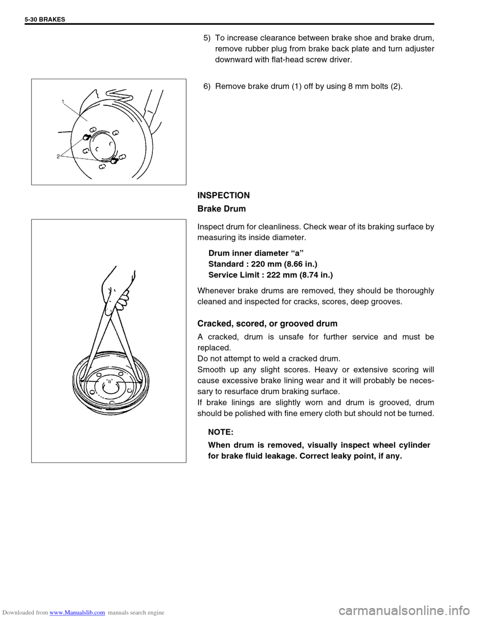
6) Remove brake drum (1) off by using 8 mm bolts (2).
INSPECTION
Brake Drum
Inspect drum for cleanliness. Check wear of its braking surface by
measuring its inside diameter.
Drum inner diameter “a”
Standard : 220 mm (8.66 in.)
Service Limit : 222 mm (8.74 in.)
Whenever brake drums are removed, they should be thoroughly
cleaned and inspected for cracks, scores, deep grooves.
Cracked, scored, or grooved drum
A cracked, drum is unsafe for further service and must be
replaced.
Do not attempt to weld a cracked drum.
Smooth up any slight scores. Heavy or extensive scoring will
cause excessive brake lining wear and it will probably be neces-
sary to resurface drum braking surface.
If brake linings are slightly worn and drum is grooved, drum
should be polished with fine emery cloth but should not be turned.
NOTE:
When drum is removed, visually inspect wheel cylinder
for brake fluid leakage. Correct leaky point, if any.
Page 308 of 687

Downloaded from www.Manualslib.com manuals search engine BRAKES 5-47
CLEARANCE BETWEEN BOOSTER PISTON ROD AND
MASTER CYLINDER PISTON
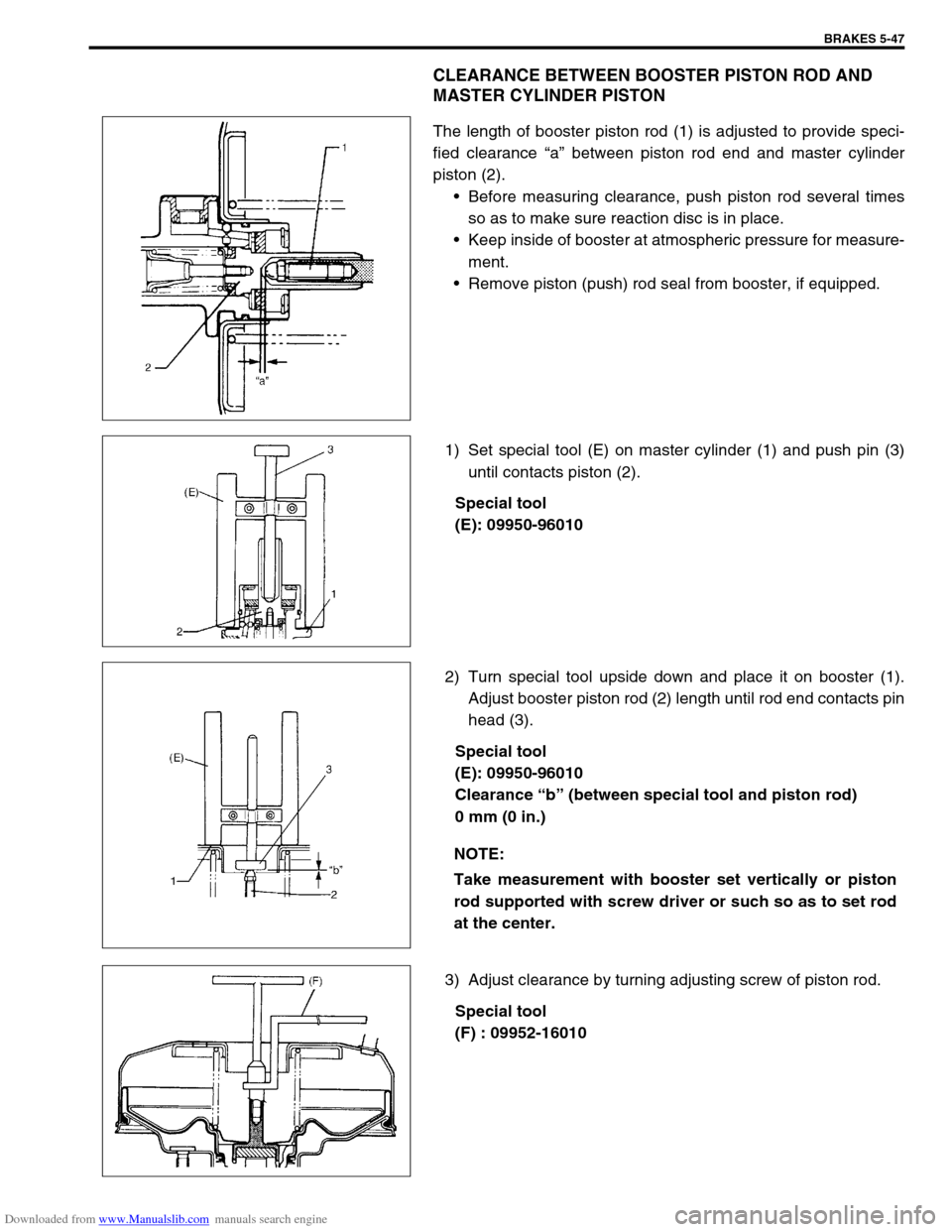
The length of booster piston rod (1) is adjusted to provide speci-
fied clearance “a” between piston rod end and master cylinder
piston (2).
Before measuring clearance, push piston rod several times
so as to make sure reaction disc is in place.
Keep inside of booster at atmospheric pressure for measure-
ment.
Remove piston (push) rod seal from booster, if equipped.
1) Set special tool (E) on master cylinder (1) and push pin (3)
until contacts piston (2).
Special tool
(E): 09950-96010
2) Turn special tool upside down and place it on booster (1).
Adjust booster piston rod (2) length until rod end contacts pin
head (3).
Special tool
(E): 09950-96010
Clearance “b” (between special tool and piston rod)
0 mm (0 in.)
3) Adjust clearance by turning adjusting screw of piston rod.
Special tool
(F) : 09952-16010
NOTE:
Take measurement with booster set vertically or piston
rod supported with screw driver or such so as to set rod
at the center.
Page 380 of 687
![SUZUKI JIMNY 2005 3.G Service Workshop Manual Downloaded from www.Manualslib.com manuals search engine ENGINE GENERAL INFORMATION AND DIAGNOSIS 6-23
[D] Fig. 4 for Step 7 or 8 / [E] Fig. 5 for Step 10 / [F] Fig. 6 for Step 13
Engine diagnosis tab SUZUKI JIMNY 2005 3.G Service Workshop Manual Downloaded from www.Manualslib.com manuals search engine ENGINE GENERAL INFORMATION AND DIAGNOSIS 6-23
[D] Fig. 4 for Step 7 or 8 / [E] Fig. 5 for Step 10 / [F] Fig. 6 for Step 13
Engine diagnosis tab](/manual-img/20/7588/w960_7588-379.png)
Downloaded from www.Manualslib.com manuals search engine ENGINE GENERAL INFORMATION AND DIAGNOSIS 6-23
[D] Fig. 4 for Step 7 or 8 / [E] Fig. 5 for Step 10 / [F] Fig. 6 for Step 13
Engine diagnosis table
Perform troubleshooting referring to following table when ECM has no DTC and no abnormality found in visual
inspection and engine basic inspection previously.
Condition Possible Cause Reference Item
Hard Starting
(Engine cranks OK)Faulty ignition coil Ignition coil assembly in Section 6F.
Faulty CMP sensing rotor or CKP sensing
rotorCMP sensing rotor or CKP sensing
rotor inspection in Section 6E.
Faulty idle air control system Diagnostic Flow Table B-4
Faulty ECT sensor, TP sensor, CKP sen-
sor, CMP sensor or MAP sensorECT sensor, TP sensor, CKP sensor,
CMP sensor or MAP sensor in Sec-
tion 6E.
Fuel pressure out of specification Diagnostic Flow Table B-3
Faulty fuel injector Diagnostic Flow Table B-1
Faulty ECM Inspection of ECM and its circuit in
this section.
Malfunctioning PCV system PCV system in Section 6E.
Low compression Compression check in Section 6A1.
Improper valve lash Valve lash in Section 6A1.
Improper valve timing Timing chain and chain tensioner in
Section 6A1.
Compression leak from valve seat Valves and cylinder head in Section
6A1.
Sticky valve stem Valves and cylinder head in Section
6A1.
Weak or damaged valve springs Valves and cylinder head in Section
6A1.
Compression leak at cylinder head gasket Valves and cylinder head in Section
6A1.
Sticking or damaged piston ring Pistons, piston rings, connecting rods
and cylinders in Section 6A1.
Worn piston, ring or cylinder Pistons, piston rings, connecting rods
and cylinders in Section 6A1.
Page 382 of 687

Downloaded from www.Manualslib.com manuals search engine ENGINE GENERAL INFORMATION AND DIAGNOSIS 6-25
Excessive detonation
(The engine makes
sharp metallic knocks
that change with throt-
tle opening.
Sounds like pop corn
popping.)Engine overheating Refer to “Overheating” of this table.
Faulty spark plug Spark plugs in Section 6F.
Clogged fuel filter and fuel lines Diagnostic Flow Table B-3
Malfunctioning EGR valve (if equipped) EGR system in Section 6E.
Poor performance of knock sensor, ECT
sensor or MAP sensorKnock sensor in this section, ECT
sensor or MAP sensor in Section 6E.
Faulty injector Diagnostic Flow Table B-1
Faulty ECM Inspection of ECM and its circuit in
this section.
Excessive combustion chamber deposits Piston and cylinder head in Section
6A1.
Overheating
Inoperative thermostat Thermostat in Section 6B.
Faulty A/C condenser fan motor or its cir-
cuitA/C condenser fan control system
check in Section 6E.
Loose or slip water pump belt ITEM1-1 Drive belt inspection and
change in Section 0B.
Poor water pump performance Water pump in Section 6B.
Clogged or leaky radiator Radiator in Section 6B.
Improper engine oil grade ITEM1-3 Engine oil and oil filter
change in Section 0B.
Clogged oil filter or oil strainer Oil pressure check in Section 6A1.
Poor oil pump performance Oil pressure check in Section 6A1.
Dragging brakes Diagnosis Table in Section 5.
Slipping clutch Diagnosis Table in Section 7C.
Blown cylinder head gasket Valves and cylinder head in Section
6A1.
Poor gasoline mileage
Faulty ignition coil Ignition coil assembly in Section 6F.
Fuel pressure out of specification Diagnostic Flow Table B-3
Faulty TP sensor, ECT sensor or MAP
sensorTP sensor, ECT sensor or MAP sen-
sor in Section 6E.
Faulty injector Diagnostic Flow Table B-1
Faulty ECM Inspection of ECM and its circuit in
this section.
Malfunctioning EGR valve (if equipped) EGR system in Section 6E.
High idle speed Refer to item “Improper Engine Idle
Speed” previously outlined.
Low compression Previously outlined.
Poor valve seating Valves and cylinder head in Section
6A1.
Dragging brakes Diagnosis Table in Section 5.
Slipping clutch Diagnosis Table in Section 7C.
Thermostat out of order Thermostat in Section 6B.
Improper tire pressure Refer to Section 3F. Condition Possible Cause Reference Item
Page 383 of 687

Downloaded from www.Manualslib.com manuals search engine 6-26 ENGINE GENERAL INFORMATION AND DIAGNOSIS
Excessive engine oil
consumptionSticky piston ring Pistons, piston rings, connecting rods
and cylinders in Section 6A1.
Worn piston and cylinder Pistons, piston rings, connecting rods
and cylinders in Section 6A1.
Worn piston ring groove and ring Pistons, piston rings, connecting rods
and cylinders in Section 6A1.
Improper location of piston ring gap Pistons, piston rings, connecting rods
and cylinders in Section 6A1.
Worn or damaged valve stem seal Valves and cylinder head in Section
6A1.
Worn valve stem Valves and cylinder head in Section
6A1.
Low oil pressure
Improper oil viscosity ITEM1-3 Engine oil and oil filter
change in Section 0B.
Malfunctioning oil pressure switch Oil pressure switch in Section 8.
Clogged oil strainer Oil pan and oil pump strainer in Sec-
tion 6A1.
Functional deterioration of oil pump Oil pump in Section 6A1.
Worn oil pump relief valve Oil pump in Section 6A1.
Excessive clearance in various sliding
partsRefer to Section 6A1.
Engine noise
See NOTE below.Improper valve lash Valve lash in Section 6A1.
Worn valve stem and guide Valves and cylinder head in Section
6A1.
Weak or broken valve spring Valve springs in Section 6A1.
Warped or bent valve Valves and cylinder head in Section
6A1.
Loose camshaft housing bolts Camshaft in Section 6A1.
Worn piston, ring and cylinder bore Pistons and cylinders in Section 6A1.
Worn crankpin bearing Crankpin and connecting rod bearing
in Section 6A1.
Worn crankpin Crankpin and connecting rod bearing
in Section 6A1.
Loose connecting rod nuts Connecting rod in Section 6A1.
Low oil pressure Previously outlined.
Worn crankshaft journal bearing Main bearings, Crankshaft and cylin-
der block in Section 6A1.
Worn crankshaft journal Main bearings, Crankshaft and cylin-
der block in Section 6A1.
Loose lower crankcase (bearing cap) bolts Main bearings, Crankshaft and cylin-
der block in Section 6A1.
Excessive crankshaft thrust play Main bearings, Crankshaft and cylin-
der block in Section 6A1. Condition Possible Cause Reference Item
NOTE:
Before checking the mechanical noise, make sure that :
Ignition timing is properly adjusted.
Specified spark plug is used.
Specified fuel is used.
Page 388 of 687

Downloaded from www.Manualslib.com manuals search engine ENGINE GENERAL INFORMATION AND DIAGNOSIS 6-31
THROTTLE POS (ABSOLUTE THROTTLE POSITION, %)
When throttle position sensor is fully closed position, throttle opening is indicated as 0% and 100% full open
position.
OXYGEN SENSOR B1 S1 (HEATED OXYGEN SENSOR-1, V)
It indicates output voltage of HO2S-1 installed on exhaust manifold (pre-catalyst).
OXYGEN SENSOR B1 S2 (HEATED OXYGEN SENSOR-2, V)
It indicates output voltage of HO2S-2 installed on exhaust pipe (post-catalyst). It is used to detect catalyst dete-
rioration.
DESIRED IDLE (DESIRED IDLE SPEED, rpm)
The Desired Idle Speed is an ECM internal parameter which indicates the ECM requested idle. If the engine is
not running, this number is not valid.
TP SENSOR VOLT (THROTTLE POSITION SENSOR OUTPUT VOLTAGE, V)
The Throttle Position Sensor reading provides throttle valve opening information in the form of voltage.
INJ PULSE WIDTH (FUEL INJECTION PULSE WIDTH, msec.)
This parameter indicates time of the injector drive (valve opening) pulse which is output from ECM (but injector
drive time of NO.1 cylinder for multiport fuel injection).
IAC FLOW DUTY (IDLE AIR (SPEED) CONTROL DUTY, %)
This parameter indicates current flow time rate within a certain set cycle of IAC valve (valve opening rate) which
controls the amount of bypass air (idle speed).
TOTAL FUEL TRIM (%)
The value of Total Fuel Trim is obtained by putting values of short Term Fuel Trim and Long Term Fuel Trim
together. This value indicates how much correction is necessary to keep the air / fuel mixture stoichiometrical.
BATTERY VOLTAGE (V)
This parameter indicates battery positive voltage inputted from main relay to ECM.
CANIST PURGE DUTY (EVAP CANISTER PURGE FLOW DUTY, %)
This parameter indicates valve ON (valve open) time rate within a certain set cycle of EVAP purge solenoid
valve which controls the amount of EVAP purge.
0% means that the purge valve is completely closed while 100% is a fully open valve.
CLOSED THROTTLE POSITION (ON / OFF)
This parameter will read ON when throttle valve is fully closed, or OFF when the throttle is not fully closed.
FUEL CUT (ON / OFF)
ON : Fuel being cut (output signal to injector is stopped)
OFF : Fuel not being cut
A/C CONDENSER FAN (A/C CONDENSER FAN RELAY, ON / OFF)
ON : Command for condenser fan relay operation being output.
OFF : Command for relay operation not being output.
ELECTRIC LOAD (ON / OFF)
ON : Headlight, small light, heater fan or rear window defogger ON signal inputted.
OFF : Above electric loads all turned OFF.
A/C SWITCH (ON / OFF)
ON : Command for A/C operation being output from ECM to A/C amplifier.
OFF : Command for A/C operation not being output.