Page 362 of 687

Downloaded from www.Manualslib.com manuals search engine ENGINE GENERAL INFORMATION AND DIAGNOSIS 6-5
Fuel pressure relief procedure
After making sure that engine is cold, release fuel pressure as fol-
lows.
1) Place transmission gear shift lever in “Neutral” (Shift selector
lever to “P” range for A/T model), set parking brake, and
block drive wheels.
2) Remove relay box cover.
3) Disconnect fuel pump relay (1) from its connector.
4) Remove fuel filler cap to release fuel vapor pressure in fuel
tank and then reinstall it.
5) Start engine and run it till it stops for lack of fuel. Repeat
cranking engine 2-3 times for about 3 seconds each time to
dissipate fuel pressure in lines. Fuel connections are now
safe for servicing.
6) Upon completion of servicing, connect fuel pump relay (1) to
its connector.
Fuel leakage check procedure
After performing any service on fuel system, check to make sure
that there are no fuel leakages as follows.
1) Turn ON ignition switch for 3 seconds (to operate fuel pump)
and then turn it OFF.
Repeat this (ON and OFF) 3 or 4 times and apply fuel pres-
sure to fuel line. (till fuel pressure is felt by hand placed on
fuel feed hose.)
2) In this state, check to see that there are no fuel leakages
from any part of fuel system. CAUTION:
This work must not be done when engine is hot. If done
so, it may cause adverse effect to catalyst.
Page 554 of 687

Downloaded from www.Manualslib.com manuals search engine ENGINE MECHANICAL (M13 ENGINE) 6A1-73
Unit Repair Overhaul
Engine Assembly
REMOVAL
1) Relieve fuel pressure referring to “Fuel Pressure Relief Pro-
cedure” in Section 6.
2) Disconnect negative cable at battery.
3) Remove engine hood after disconnecting windshield washer
hose.
4) Remove A/C compressor and/or P/S pump belt (if
equipped).
5) Remove generator belt.
6) Drain engine oil.
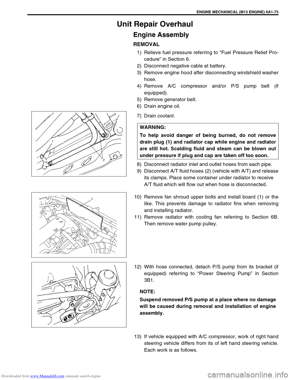
7) Drain coolant.
8) Disconnect radiator inlet and outlet hoses from each pipe.
9) Disconnect A/T fluid hoses (2) (vehicle with A/T) and release
its clamps. Place some container under radiator to receive
A/T fluid which will flow out when hose is disconnected.
10) Remove fan shroud upper bolts and install board (1) or the
like. This prevents damage to radiator fins when removing
and installing radiator.
11) Remove radiator with cooling fan referring to Section 6B.
Then remove water pump pulley.
12) With hose connected, detach P/S pump from its bracket (if
equipped) referring to “Power Steering Pump” in Section
3B1.
13) If vehicle equipped with A/C compressor, work of right hand
steering vehicle differs from its of left hand steering vehicle.
Each work is as follows. WARNING:
To help avoid danger of being burned, do not remove
drain plug (1) and radiator cap while engine and radiator
are still hot. Scalding fluid and steam can be blown out
under pressure if plug and cap are taken off too soon.
NOTE:
Suspend removed P/S pump at a place where no damage
will be caused during removal and installation of engine
assembly.
Page 628 of 687

Downloaded from www.Manualslib.com manuals search engine ENGINE AND EMISSION CONTROL SYSTEM 6E-23
6) Start engine and warm it up to normal operating tempera-
ture.
7) Measure fuel pressure at idling.
If measured pressure doesn’t satisfy specification, refer to
“Diagnostic Flow Table B-3” in Section 6 and check each
possibly defective part. Replace if found defective.
8) After checking fuel pressure, remove fuel pressure gauge.
9) Remove special tools from fuel delivery pipe.
10) Connect fuel feed hose to fuel delivery pipe and clamp it
securely.
11) With engine “OFF” and ignition switch “ON”, check for fuel
leaks.
Fuel pump
ON-VEHICLE INSPECTION
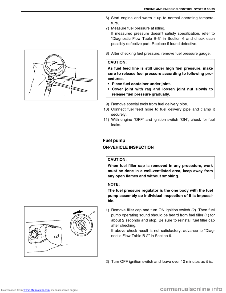
1) Remove filler cap and turn ON ignition switch (2). Then fuel
pump operating sound should be heard from fuel filler (1) for
about 2 seconds and stop. Be sure to reinstall fuel filler cap
after checking.
If above check result is not satisfactory, advance to “Diag-
nostic Flow Table B-2” in Section 6.
2) Turn OFF ignition switch and leave over 10 minutes as it is.CAUTION:
As fuel feed line is still under high fuel pressure, make
sure to release fuel pressure according to following pro-
cedures.
Place fuel container under joint.
Cover joint with rag and loosen joint nut slowly to
release fuel pressure gradually.
CAUTION:
When fuel filler cap is removed in any procedure, work
must be done in a well-ventilated area, keep away from
any open flames and without smoking.
NOTE:
The fuel pressure regulator is the one body with the fuel
pump assembly so individual inspection of it is impossi-
ble.