Page 188 of 687

Downloaded from www.Manualslib.com manuals search engine FRONT SUSPENSION 3D-15
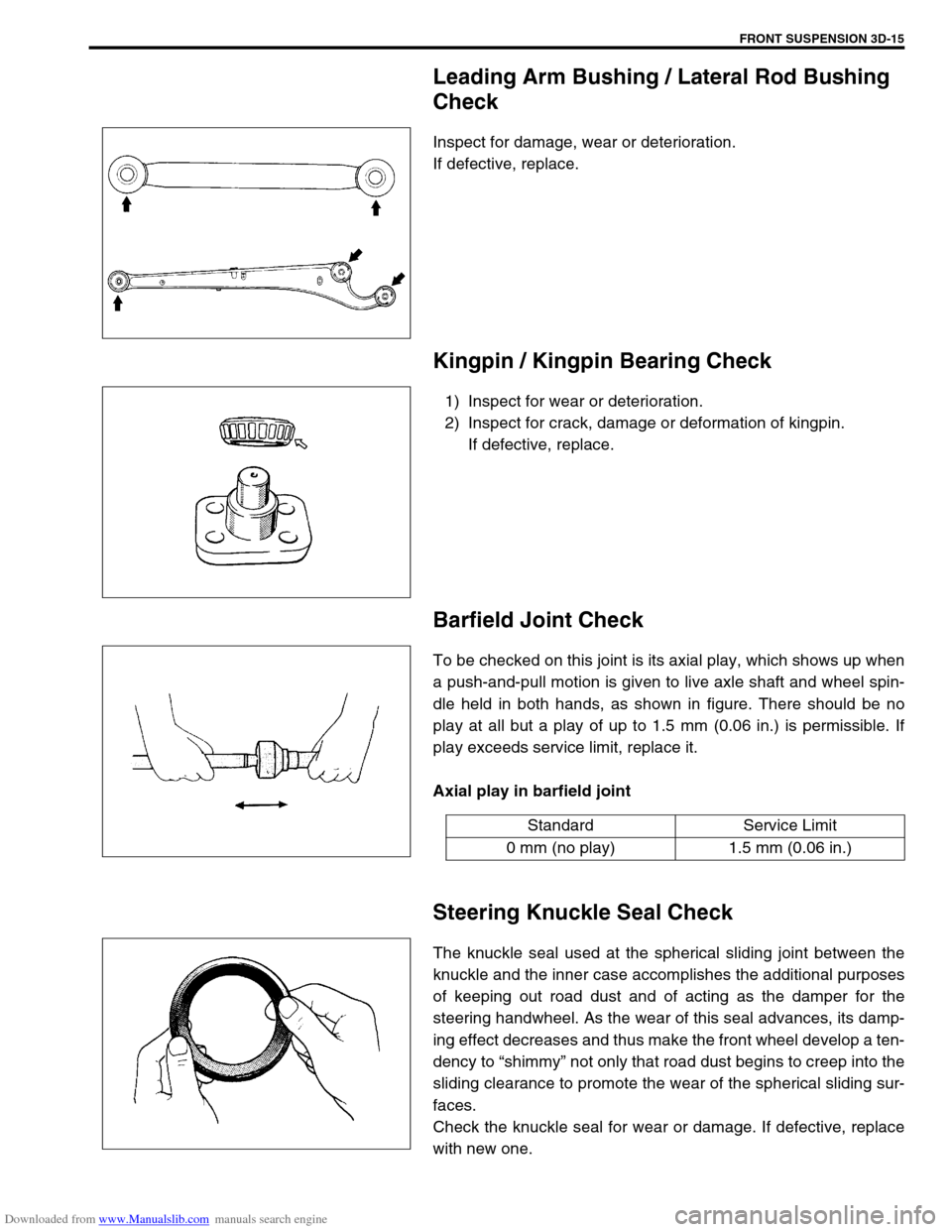
Leading Arm Bushing / Lateral Rod Bushing
Check
Inspect for damage, wear or deterioration.
If defective, replace.
Kingpin / Kingpin Bearing Check
1) Inspect for wear or deterioration.
2) Inspect for crack, damage or deformation of kingpin.
If defective, replace.
Barfield Joint Check
To be checked on this joint is its axial play, which shows up when
a push-and-pull motion is given to live axle shaft and wheel spin-
dle held in both hands, as shown in figure. There should be no
play at all but a play of up to 1.5 mm (0.06 in.) is permissible. If
play exceeds service limit, replace it.
Axial play in barfield joint
Steering Knuckle Seal Check
The knuckle seal used at the spherical sliding joint between the
knuckle and the inner case accomplishes the additional purposes
of keeping out road dust and of acting as the damper for the
steering handwheel. As the wear of this seal advances, its damp-
ing effect decreases and thus make the front wheel develop a ten-
dency to “shimmy” not only that road dust begins to creep into the
sliding clearance to promote the wear of the spherical sliding sur-
faces.
Check the knuckle seal for wear or damage. If defective, replace
with new one.
Standard Service Limit
0 mm (no play) 1.5 mm (0.06 in.)
Page 189 of 687
Downloaded from www.Manualslib.com manuals search engine 3D-16 FRONT SUSPENSION
Wheel Disc, Nut and Bearing Check
1) Inspect each wheel disc for dents, distortion and cracks.
Disc in badly damaged condition must be replaced.
2) Check wheel nuts for tightness and as necessary, retighten
them to specification.
Tightening torque
Wheel nuts
(a) : 95 N·m (9.5 kg-m, 69.0 lb-ft)
3) Check wheel bearing for wear. After retightening lock nut to
specified torque, apply dial gauge to wheel hub center and
measure thrust play.
Wheel bearing thrust play limit
: 0.05 mm (0.002 in)
When measurement exceeds limit, replace bearing.
4) By rotating wheel actually, check wheel bearing for noise and
smooth rotation. If defective, replace bearing.
Page 194 of 687

Downloaded from www.Manualslib.com manuals search engine FRONT SUSPENSION 3D-21
5) Install wheel and tighten wheel nuts to specified torque.
Tightening torque
Wheel nuts
(a) : 95 N·m (9.5 kg-m, 69.0 lb-ft)
6) Lower hoist.
7) Confirm front end (wheel) alignment, referring to “Prelimi-
nary Checks Prior to Adjusting Front Alignment” in Section
3A.
Bump Stopper and Spring Upper Seat
REMOVAL
1) Remove coil spring, refer to “Coil Spring” in this section.
2) Remove bump stopper and spring upper seat.
INSTALLATION
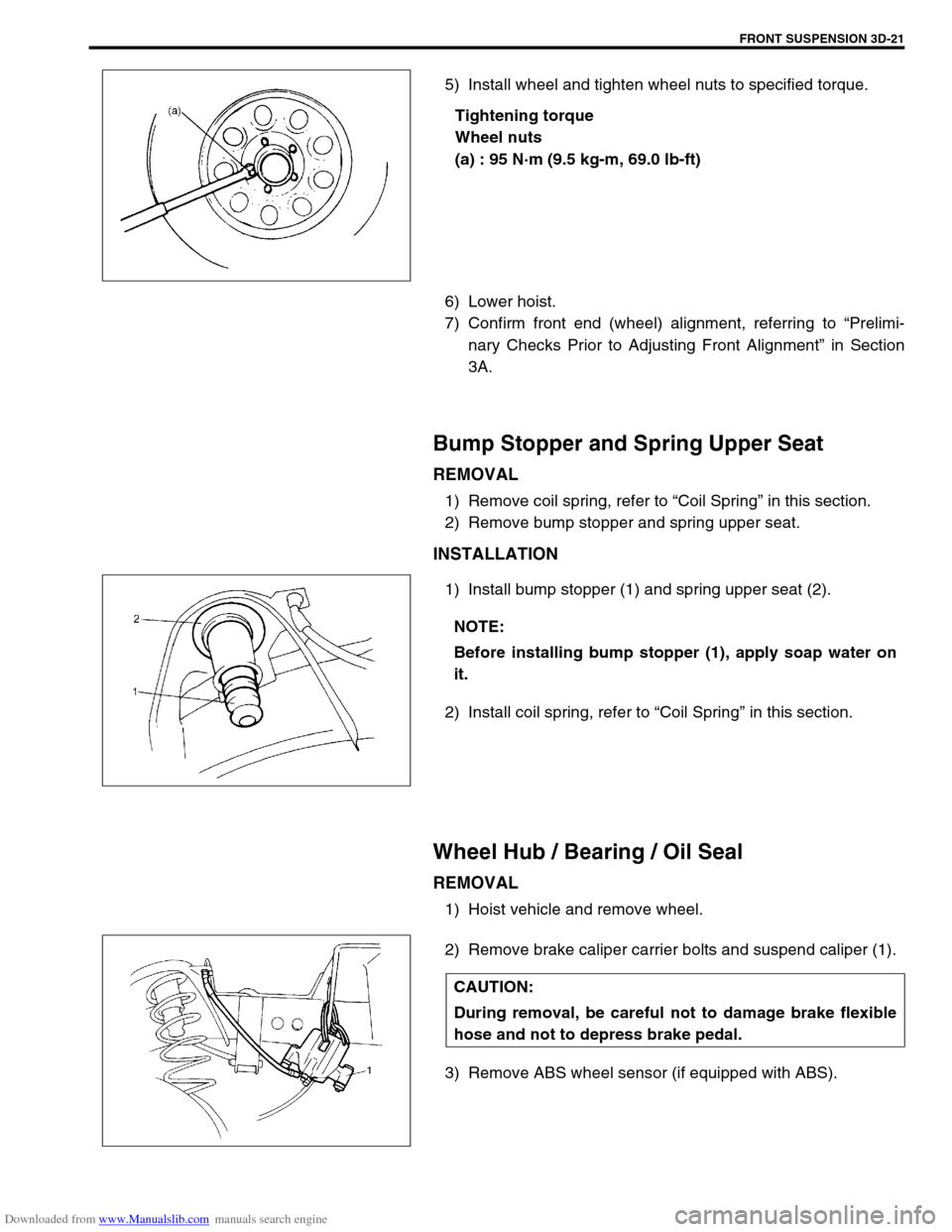
1) Install bump stopper (1) and spring upper seat (2).
2) Install coil spring, refer to “Coil Spring” in this section.
Wheel Hub / Bearing / Oil Seal
REMOVAL
1) Hoist vehicle and remove wheel.
2) Remove brake caliper carrier bolts and suspend caliper (1).
3) Remove ABS wheel sensor (if equipped with ABS).
NOTE:
Before installing bump stopper (1), apply soap water on
it.
CAUTION:
During removal, be careful not to damage brake flexible
hose and not to depress brake pedal.
Page 195 of 687
Downloaded from www.Manualslib.com manuals search engine 3D-22 FRONT SUSPENSION
4) Remove brake disc.
5) Remove front wheel bearing lock nut as follows.
For 2WD model :
a) Remove hub cap.
b) Remove front wheel bearing lock plate (1) by loosening 4
screws (2).
For 4WD model :
a) Remove air locking hub assembly (1).
b) Remove front axle shaft circlip and wheel spindle thrust
washer.
c) Uncaulk front wheel bearing lock nut. NOTE:
If brake disc can not be removed by hand, using 8 mm
bolts.
1. Wheel hub
Page 196 of 687
Downloaded from www.Manualslib.com manuals search engine FRONT SUSPENSION 3D-23
6) Remove front wheel bearing lock nut by using special tool.
Special tool
(A) : 09944-77020 (For 4WD)
(A) : 09951-16050 (For 2WD)
7) Remove front wheel bearing washer.
8) Remove wheel hub complete (1) with bearings (2) and oil
seal (4).
Special tool
(A) : 09943-35511 or 09943-35512
(B) : 09942-15510
9) Remove sensor rotor from wheel hub as shown (if equipped
with ABS).
10) Remove wheel bearing oil seal and circlip.
3. Circlip
NOTE:
If wheel hub can not be removed by hand, use special
tools as shown.
CAUTION:
Pull out sensor rotor from wheel hub gradually and
evenly.
Attempt to pull it out partially may cause it to be
deformed.
1. Sensor rotor
2. Wheel hub
3. Vise
4. Flat end rod
Page 197 of 687
Downloaded from www.Manualslib.com manuals search engine 3D-24 FRONT SUSPENSION
11) Using hydraulic press (1) and special tool remove wheel
bearing (2).
Special tool
(A) : 09913-75520
12) Remove hub bolts from hub.
INSTALLATION
1) Insert new stud in hub hole. Rotate stud slowly to assure ser-
rations are aligned with those made by original bolt.
2) Using special tool, press-fit wheel bearing (3) until its end
contacts stepped surface of wheel hub (4).
Special tool
(A) : 09944-78210
3) Install bearing circlip.
4) Drive in wheel bearing oil seal (1) by using special tools.
Special tool
(B) : 09944-66010
(C) : 09924-74510
1. Oil hydraulic press
2. Hub bolt
CAUTION:
Press-fit wheel bearing (3) vertically to hub (4).
1. Oil hydraulic press
2. Steel plate
Page 198 of 687

Downloaded from www.Manualslib.com manuals search engine FRONT SUSPENSION 3D-25
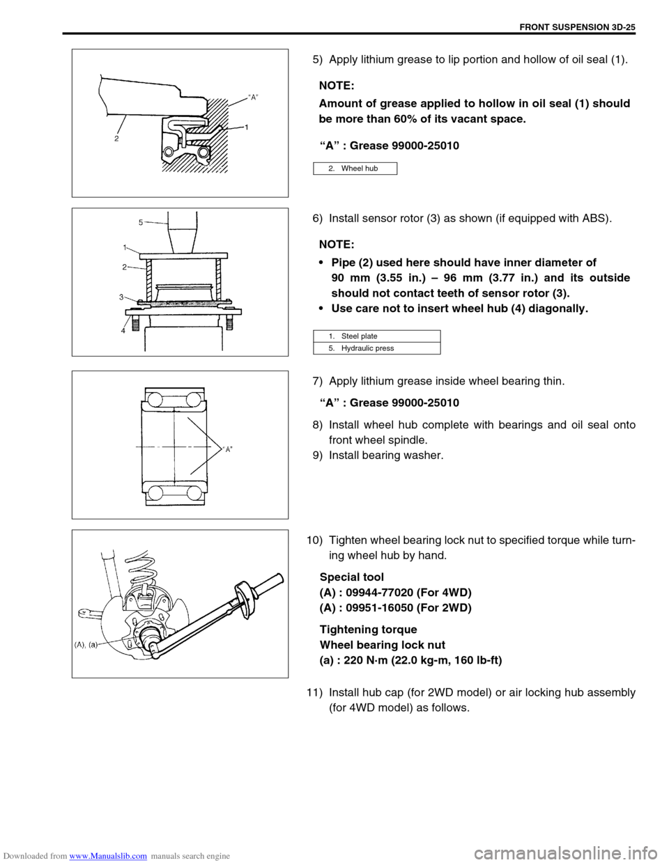
5) Apply lithium grease to lip portion and hollow of oil seal (1).
“A” : Grease 99000-25010
6) Install sensor rotor (3) as shown (if equipped with ABS).
7) Apply lithium grease inside wheel bearing thin.
“A” : Grease 99000-25010
8) Install wheel hub complete with bearings and oil seal onto
front wheel spindle.
9) Install bearing washer.
10) Tighten wheel bearing lock nut to specified torque while turn-
ing wheel hub by hand.
Special tool
(A) : 09944-77020 (For 4WD)
(A) : 09951-16050 (For 2WD)
Tightening torque
Wheel bearing lock nut
(a) : 220 N·m (22.0 kg-m, 160 lb-ft)
11) Install hub cap (for 2WD model) or air locking hub assembly
(for 4WD model) as follows. NOTE:
Amount of grease applied to hollow in oil seal (1) should
be more than 60% of its vacant space.
2. Wheel hub
NOTE:
Pipe (2) used here should have inner diameter of
90 mm (3.55 in.) – 96 mm (3.77 in.) and its outside
should not contact teeth of sensor rotor (3).
Use care not to insert wheel hub (4) diagonally.
1. Steel plate
5. Hydraulic press
Page 199 of 687

Downloaded from www.Manualslib.com manuals search engine 3D-26 FRONT SUSPENSION
For 2WD model:
a) Using lock plate (1), lock bearing lock nut. If lock screw hole
is not aligned with screw hole in lock nut, turn lock nut in
tightening direction till they align.
Tightening torque
Wheel bearing lock washer screw
(a) : 1.5 N·m (0.15 kg-m, 1.0 lb-ft)
b) Remove grease, old sealant and dusts from mating sur-
faces of hub cap (1) and wheel hub (2) to clean, apply
water tight sealant to hub cap mating surface evenly, and
install hub cap (1) to wheel hub (2).
“A” : Sealant 99000-31090
For 4WD model:
a) Caulk front wheel bearing lock nut at groove of spindle.
b) Apply lithium grease thinly to both surface, all around of
front spindle thrust washer (1).
“A” : Grease 99000-25010
NOTE:
When installing hub cap (1), hammer lightly several
locations on the collar of cap until collar comes closely
into contact with wheel hub (2).
If fitting part of cap is deformed or damaged or if it is
fitted loosely, replace with new one.