Page 674 of 687

Downloaded from www.Manualslib.com manuals search engine CHARGING SYSTEM 6H-7
How to use the temperature-corrected state-of-charge
graph
Suppose your S.G. reading is 1.28 and the battery temperature is
–5 °C (23 °F). Locate the intersection of the –5 °C line and the
1.28 S.G. line.
The intersection is within the “A” zone (shaded area in the graph)
and that means CHARGED STATE.
To know how much the battery is charged, draw a line parallel to
the zone demarcation line and extend it to the right till it meets
with the percentage scale. In the present example, the line meets
at about 85% point on the percentage scale. Therefore, the bat-
tery is charged up to the 85% level.
Generator
Trouble in charging system will show up as one or more of follow-
ing conditions:
1) Faulty indicator lamp operation.
2) An undercharged battery as evidenced by slow cranking or
indicator dark.
3) An overcharged battery as evidenced by excessive spewing
of electrolyte from vents.
Noise from generator may be caused by a loose drive pulley,
loose mounting bolts, worn or dirty bearings, defective diode, or
defective stator.
FAULTY INDICATOR LAMP OPERATION
CAUTION:
Do not mistake polarities of IG terminal and L terminal.
Do not make a short circuit between IG and L termi-
nals. Always connect these terminals through a lamp.
Do not connect any load between L and E.
When connecting a charger or a booster battery to
vehicle battery, refer to this section describing battery
charging.
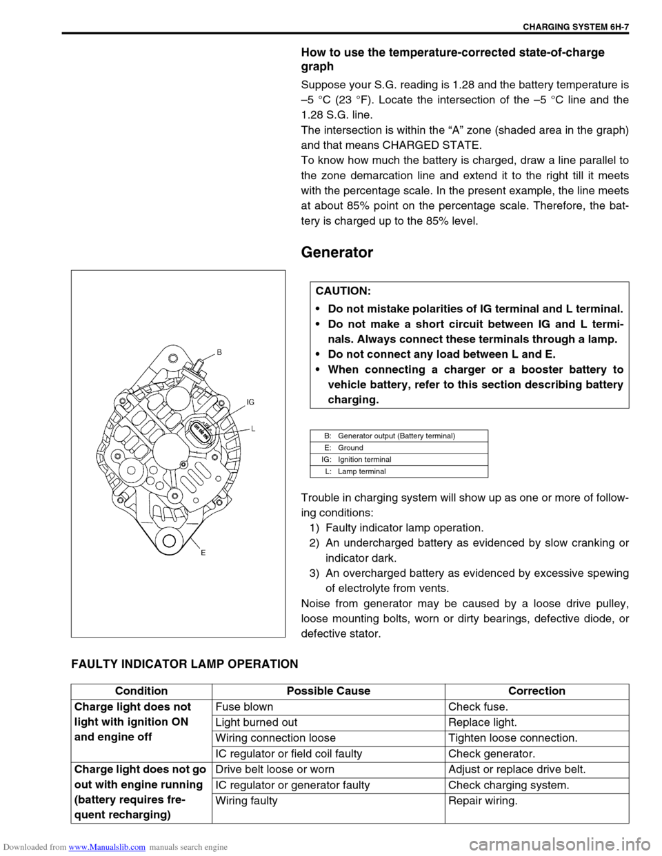
B: Generator output (Battery terminal)
E: Ground
IG: Ignition terminal
L: Lamp terminal
Condition Possible Cause Correction
Charge light does not
light with ignition ON
and engine offFuse blown Check fuse.
Light burned out Replace light.
Wiring connection loose Tighten loose connection.
IC regulator or field coil faulty Check generator.
Charge light does not go
out with engine running
(battery requires fre-
quent recharging)Drive belt loose or worn Adjust or replace drive belt.
IC regulator or generator faulty Check charging system.
Wiring faulty Repair wiring.
Page 680 of 687
Downloaded from www.Manualslib.com manuals search engine CHARGING SYSTEM 6H-13
Remounting
1) Mount generator on the generator bracket.
2) Tighten generator bolts.
Tightening torque
Generator pivot bolt
(a) : 23 N·m (2.3 kg-m, 16.5 lb-ft)
(b) : 50 N·m (5.0 kg-m, 36.0 lb-ft)
3) Install generator (cooling fan) belt. Refer to “Water Pump
Belt and Cooling Fan” in Section 6B.
4) Connect “B” terminal wire (3) and coupler to generator.
Tightening torque
“B” terminal outer nut of generator
(b) : 8.0 N·m (0.8 kg-m, 6.0 lb-ft)
5) Install canister.
6) Connect negative (–) cable at battery.
Disassembly and reassembly
1. Upper generator bolt (Short)
2. Lower generator bolt (Long)
1. Pulley 5. Rotor 9. Rear housing
2. Front housing 6. Stator 10. Brush
3. Bearing 7. IC regulator
4. Retainer 8. Rectifier
Page 683 of 687
Downloaded from www.Manualslib.com manuals search engine 6H-16 CHARGING SYSTEM
Drive End Bearing
Check that the bearing is not rough or worn.
End Housing Bearing
Check that the bearing is not rough or worn.
When removal is necessary, use bearing puller to remove end
housing bearing (1).
Replace Brush
1) Unsolder and remove the brush and spring.
2) Run the wire of a new brush through the spring and the hole
in the brush holder, and insert the spring and brush into the
brush holder.
3) Solder the brush wire to the brush holder at specified
exposed length.
Exposed brush length
“a” : 10.5 mm (0.413 in.)
4) Check that the brush moves smoothly in the brush holder.
5) Cut off the excess wire.
6) Apply insulation paint to the soldered area.
CAUTION:
Be careful not to distort cooling fan blade while applying
puller.
Page 684 of 687

Downloaded from www.Manualslib.com manuals search engine CHARGING SYSTEM 6H-17
Specifications
Battery
55B24R TYPE
38B20R TYPE
Generator
Tightening Torque Specification
Rated capacity 36 AH/5HR, 12 Volts
Electrolyte 3.1 L (6.55/5.46 US/lmp pt)
Electrolyte S.G. 1.28 when fully charged at 20 °C (68 °F)
Rated capacity 28 AH/5HR, 12 Volts
Electrolyte 2.1 L (4.44/3.70 US/lmp pt)
Electrolyte S.G. 1.28 when fully charged at 20 °C (68 °F)
Type 70 A type
Rated voltage 12 V
Nominal output 70 A
Permissible max. speed 18,000 r/min.
No-load speed 1,300 r/min (rpm)
Setting voltage 14.4 to 15.0 V
Permissible ambient temperature–30 to 90 °C (–22 to 194 °F)
Polarity Negative ground
Rotation Clockwise viewed from pulley side
Fastening partTightening torque
Nm kg-m lb-ft
Body ground bolt 8 0.8 6.0
Generator mounting bolts 23 2.3 16.5
“B” terminal inner nut 4.2 0.42 3.0
“B” terminal outer nut 8 0.8 6.0
Pulley nut 118 11.8 85.5
Rear end frame nuts
4.50.453.5
Rear end cover nuts
Rectifier “B” bolt 3.9 0.39 3.0
Stator stud bolts 8.8 0.88 6.5
Drive end bearing plate screws 2.6 0.26 2.0
Rectifier screws
2.00.201.5
Regulator and brush holder screws
Terminal plate bolt 3.8 0.38 3.0