Page 571 of 687
Downloaded from www.Manualslib.com manuals search engine 6A1-90 ENGINE MECHANICAL (M13 ENGINE)
INSTALLATION
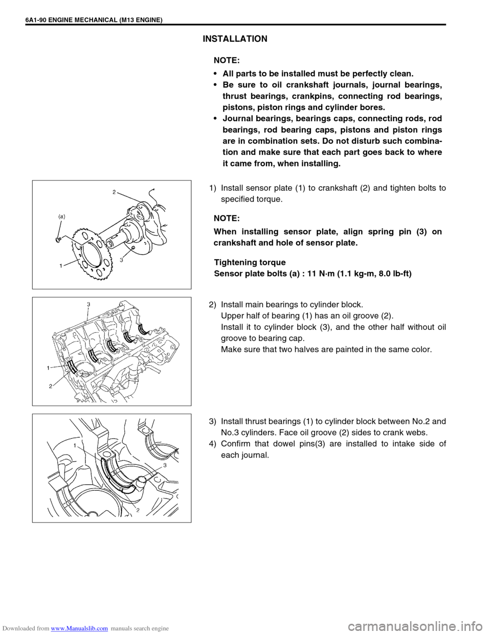
1) Install sensor plate (1) to crankshaft (2) and tighten bolts to
specified torque.
Tightening torque
Sensor plate bolts (a) : 11 N·m (1.1 kg-m, 8.0 lb-ft)
2) Install main bearings to cylinder block.
Upper half of bearing (1) has an oil groove (2).
Install it to cylinder block (3), and the other half without oil
groove to bearing cap.
Make sure that two halves are painted in the same color.
3) Install thrust bearings (1) to cylinder block between No.2 and
No.3 cylinders. Face oil groove (2) sides to crank webs.
4) Confirm that dowel pins(3) are installed to intake side of
each journal. NOTE:
All parts to be installed must be perfectly clean.
Be sure to oil crankshaft journals, journal bearings,
thrust bearings, crankpins, connecting rod bearings,
pistons, piston rings and cylinder bores.
Journal bearings, bearings caps, connecting rods, rod
bearings, rod bearing caps, pistons and piston rings
are in combination sets. Do not disturb such combina-
tion and make sure that each part goes back to where
it came from, when installing.
NOTE:
When installing sensor plate, align spring pin (3) on
crankshaft and hole of sensor plate.
Page 572 of 687
Downloaded from www.Manualslib.com manuals search engine ENGINE MECHANICAL (M13 ENGINE) 6A1-91
5) Install crankshaft to cylinder block.
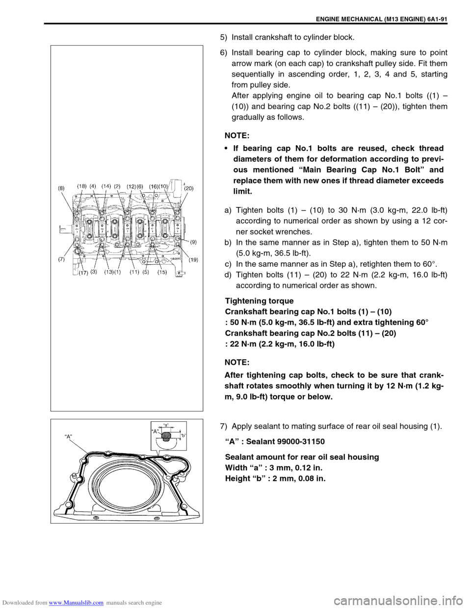
6) Install bearing cap to cylinder block, making sure to point
arrow mark (on each cap) to crankshaft pulley side. Fit them
sequentially in ascending order, 1, 2, 3, 4 and 5, starting
from pulley side.
After applying engine oil to bearing cap No.1 bolts ((1) –
(10)) and bearing cap No.2 bolts ((11) – (20)), tighten them
gradually as follows.
a) Tighten bolts (1) – (10) to 30 N·m (3.0 kg-m, 22.0 lb-ft)
according to numerical order as shown by using a 12 cor-
ner socket wrenches.
b) In the same manner as in Step a), tighten them to 50 N·m
(5.0 kg-m, 36.5 lb-ft).
c) In the same manner as in Step a), retighten them to 60°.
d) Tighten bolts (11) – (20) to 22 N·m (2.2 kg-m, 16.0 lb-ft)
according to numerical order as shown.
Tightening torque
Crankshaft bearing cap No.1 bolts (1) – (10)
: 50 N·m (5.0 kg-m, 36.5 lb-ft) and extra tightening 60°
Crankshaft bearing cap No.2 bolts (11) – (20)
: 22 N·m (2.2 kg-m, 16.0 lb-ft)
7) Apply sealant to mating surface of rear oil seal housing (1).
“A” : Sealant 99000-31150
Sealant amount for rear oil seal housing
Width “a” : 3 mm, 0.12 in.
Height “b” : 2 mm, 0.08 in. NOTE:
If bearing cap No.1 bolts are reused, check thread
diameters of them for deformation according to previ-
ous mentioned “Main Bearing Cap No.1 Bolt” and
replace them with new ones if thread diameter exceeds
limit.
NOTE:
After tightening cap bolts, check to be sure that crank-
shaft rotates smoothly when turning it by 12 N·m (1.2 kg-
m, 9.0 lb-ft) torque or below.
Page 573 of 687
Downloaded from www.Manualslib.com manuals search engine 6A1-92 ENGINE MECHANICAL (M13 ENGINE)
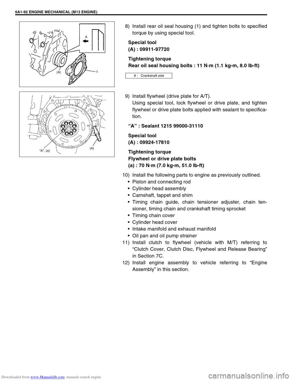
8) Install rear oil seal housing (1) and tighten bolts to specified
torque by using special tool.
Special tool
(A) : 09911-97720
Tightening torque
Rear oil seal housing bolts : 11 N·m (1.1 kg-m, 8.0 lb-ft)
9) Install flywheel (drive plate for A/T).
Using special tool, lock flywheel or drive plate, and tighten
flywheel or drive plate bolts applied with sealant to specifica-
tion.
“A” : Sealant 1215 99000-31110
Special tool
(A) : 09924-17810
Tightening torque
Flywheel or drive plate bolts
(a) : 70 N·m (7.0 kg-m, 51.0 lb-ft)
10) Install the following parts to engine as previously outlined.
Piston and connecting rod
Cylinder head assembly
Camshaft, tappet and shim
Timing chain guide, chain tensioner adjuster, chain ten-
sioner, timing chain and crankshaft timing sprocket
Timing chain cover
Cylinder head cover
Intake manifold and exhaust manifold
Oil pan and oil pump strainer
11) Install clutch to flywheel (vehicle with M/T) referring to
“Clutch Cover, Clutch Disc, Flywheel and Release Bearing”
in Section 7C.
12) Install engine assembly to vehicle referring to “Engine
Assembly” in this section.
A : Crankshaft side
Page 574 of 687

Downloaded from www.Manualslib.com manuals search engine ENGINE MECHANICAL (M13 ENGINE) 6A1-93
Required Service Material
Tightening Torque Specification
MaterialRecommended SUZUKI product
(Part Number)Use
Sealant SUZUKI BOND NO. 1207C
(99000-31150)To apply to mating surface of cylinder block and oil
pan.
To apply to mating surface of cylinder block and
timing chain cover.
To apply to sealing surface of cylinder head cover.
To apply to mating surface to rear oil seal housing.
SUZUKI BOND NO. 1207B
(99000-31140)To apply to mating surface of cylinder block, cylin-
der head and timing chain cover.
SUZUKI BOND NO. 1215
(99000-31110)To flywheel (M/T) or drive plate (A/T) bolts.
Fastening partTightening torque
Nm kg-m lb-ft
Oil pressure switch 14.0 1.4 10.5
Camshaft housing bolts
(for replacement of shim)8.0 0.8 6.0
Camshaft housing bolts 11.0 1.1 8.0
Cylinder head cover bolts 8.0 0.8 6.0
Intake manifold bolts and nuts 25.0 2.5 18.0
Exhaust manifold bolts and nuts 55.0 5.5 40.0
Exhaust pipe bolts 50.0 5.0 36.5
Exhaust manifold stiffener bolts 50.0 5.0 36.5
Oil pump strainer bolt 11.0 1.1 8.0
Oil pump strainer bracket bolt 11.0 1.1 8.0
Oil pan bolts and nuts 11.0 1.1 8.0
Oil pan drain plug 50.0 5.0 36.5
Timing chain cover bolts and nut 23.0 2.3 17.0
Crankshaft pulley bolt 150.0 15.0 108.5
Oil pump rotor plate bolts 11.0 1.1 8.0
Timing chain No.1 guide bolts 9.0 0.9 6.5
Timing chain tensioner adjuster bolts 11.0 1.1 8.0
Venturi plug 5.0 0.5 3.5
Cylinder head bolt for M8 22.0 2.2 16.0
Cylinder head bolts for M10 a) Tighten 40 N·m
b) Turn 60°
c) Turn 60°a) Tighten 4.0 kg-m
b) Turn 60°
c) Turn 60°a) Tighten 29.0 lb-ft
b) Turn 60°
c) Turn 60°
Connecting rod bearing cap nuts a) Tighten 15 N·m
b) Turn 45°
c) Turn 45°a) Tighten 1.5 kg-m
b) Turn 45°
c) Turn 45°a) Tighten 11.0 lb-ft
b) Turn 45°
c) Turn 45°
Engine mounting bolts 50.0 5.0 36.5
Page 575 of 687
Downloaded from www.Manualslib.com manuals search engine 6A1-94 ENGINE MECHANICAL (M13 ENGINE)
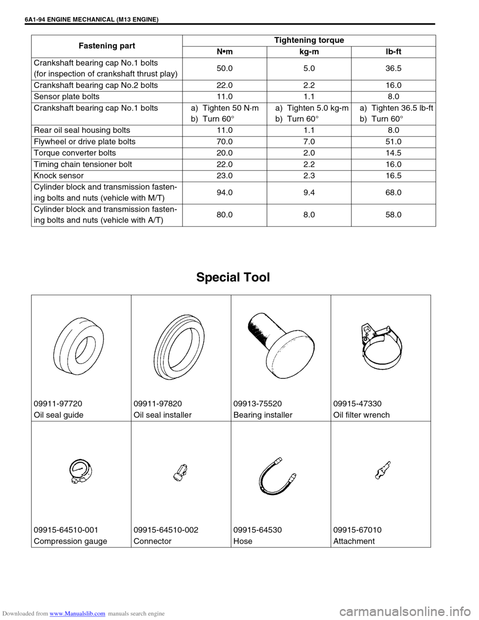
Special Tool
Crankshaft bearing cap No.1 bolts
(for inspection of crankshaft thrust play)50.0 5.0 36.5
Crankshaft bearing cap No.2 bolts 22.0 2.2 16.0
Sensor plate bolts 11.0 1.1 8.0
Crankshaft bearing cap No.1 bolts a) Tighten 50 N·m
b) Turn 60°a) Tighten 5.0 kg-m
b) Turn 60°a) Tighten 36.5 lb-ft
b) Turn 60°
Rear oil seal housing bolts 11.0 1.1 8.0
Flywheel or drive plate bolts 70.0 7.0 51.0
Torque converter bolts 20.0 2.0 14.5
Timing chain tensioner bolt 22.0 2.2 16.0
Knock sensor 23.0 2.3 16.5
Cylinder block and transmission fasten-
ing bolts and nuts (vehicle with M/T)94.0 9.4 68.0
Cylinder block and transmission fasten-
ing bolts and nuts (vehicle with A/T)80.0 8.0 58.0 Fastening partTightening torque
Nm kg-m lb-ft
09911-97720 09911-97820 09913-75520 09915-47330
Oil seal guide Oil seal installer Bearing installer Oil filter wrench
09915-64510-001 09915-64510-002 09915-64530 09915-67010
Compression gauge Connector Hose Attachment
Page 577 of 687
Downloaded from www.Manualslib.com manuals search engine 6A1-96 ENGINE MECHANICAL (M13 ENGINE)
09924-17810 09926-58010 09944-36011
Flywheel holder Bearing puller attachment Steering wheel remover
Page 581 of 687
Downloaded from www.Manualslib.com manuals search engine 6B-4 ENGINE COOLING
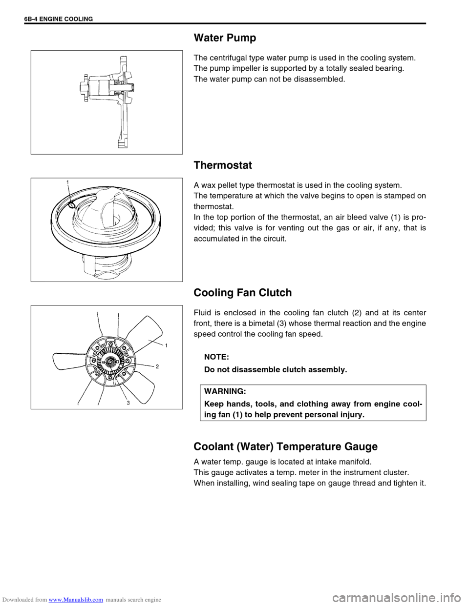
Water Pump
The centrifugal type water pump is used in the cooling system.
The pump impeller is supported by a totally sealed bearing.
The water pump can not be disassembled.
Thermostat
A wax pellet type thermostat is used in the cooling system.
The temperature at which the valve begins to open is stamped on
thermostat.
In the top portion of the thermostat, an air bleed valve (1) is pro-
vided; this valve is for venting out the gas or air, if any, that is
accumulated in the circuit.
Cooling Fan Clutch
Fluid is enclosed in the cooling fan clutch (2) and at its center
front, there is a bimetal (3) whose thermal reaction and the engine
speed control the cooling fan speed.
Coolant (Water) Temperature Gauge
A water temp. gauge is located at intake manifold.
This gauge activates a temp. meter in the instrument cluster.
When installing, wind sealing tape on gauge thread and tighten it.
NOTE:
Do not disassemble clutch assembly.
WARNING:
Keep hands, tools, and clothing away from engine cool-
ing fan (1) to help prevent personal injury.
Page 671 of 687

Downloaded from www.Manualslib.com manuals search engine 6H-4 CHARGING SYSTEM
When keeping battery on vehicle over a long period of time, follow
instructions given below.
Weekly, start the engine and run it until it reaches normal
operating temperature with engine speed of 2,000 to 3,000
rpm. Make sure all electric switches are off before storing the
vehicle.
Recharge the battery twice a month to prevent it from dis-
charging excessively. This is especially important when
ambient temperature is low.
The battery discharges even when it is not used, while vehi-
cles are being stored. Battery electrolyte can freeze and bat-
tery case can crack at cold ambient condition if battery is not
properly charged.
2) Keep the battery cable connections clean.
The cable connections, particularly at the positive (+) termi-
nal post, tend to become corroded. The product of corrosion,
or rust, on the mating faces of conductors resists the flow of
current.
Clean the terminals and fittings periodically to ensure good
metal-to-metal contact, and grease the connections after
each cleaning to protect them against rusting.
3) Be always in the know as to the state of charge of the bat-
tery. The simplest way to tell the state of charge is to carry
out a hydrometer test. The hydrometer is an instrument for
measuring the specific gravity (S.G.) of the battery electro-
lyte. The S.G. of the electrolyte is indicative of the state of
charge. Refer to “HYDROMETER TEST” in this section.
Generator
The generator is a small and high performance type with an IC regulator incorporated.
The internal components are connected electrically as shown below figure.
The generator features are as follows:
Solid state regulator is mounted inside the generator.
All regulator components are enclosed into a solid mold.
This unit along with the brush holder assembly is attached to the rear housing.
The IC regulator uses integrated circuits and controls the voltage produced by the generator, and the volt-
age setting cannot be adjusted.
The generator rotor bearings contain enough grease to eliminate the need for periodic lubrication. Two
brushes carry current through the two slip rings to the field coil mounted on the rotor, and under normal con-
ditions will provide long period of attention-free service.
The stator windings are assembled on the inside of a laminated core that forms part of the generator frame.
A condenser mounted in the rear housing suppresses radio noise.