Page 259 of 687
Downloaded from www.Manualslib.com manuals search engine 4B-6 PROPELLER SHAFTS
6) Push out bearing race (2) on flange yoke (1) in the same
way as Step 2).
7) Holding bearing race (2) by a vise (3), tap flange yoke (1)
and take out race.
8) Take out bearing race (2) on the opposite side of flange yoke
(1) in the same way as Step 5) to Step 6).
REASSEMBLY
1) Apply grease to rollers (1) in bearing races (2).
“A” : Grease 99000-25030
2) With spider (4) inserted into bearing race (2) to prevent roll-
ers in race from coming out, insert bearing race (2) into shaft
yoke (3) until it is flush with side face of shaft yoke (3), tap-
ping it by a copper hammer (1).
CAUTION:
Do not reuse spider (1), bearings (2) and circlips. Other-
wise it may damage propeller shaft or cause abnormal
vibration or noise.
NOTE:
Make sure that rollers (1) in bearing race (2) are all in
place.
Page 260 of 687

Downloaded from www.Manualslib.com manuals search engine PROPELLER SHAFTS 4B-7
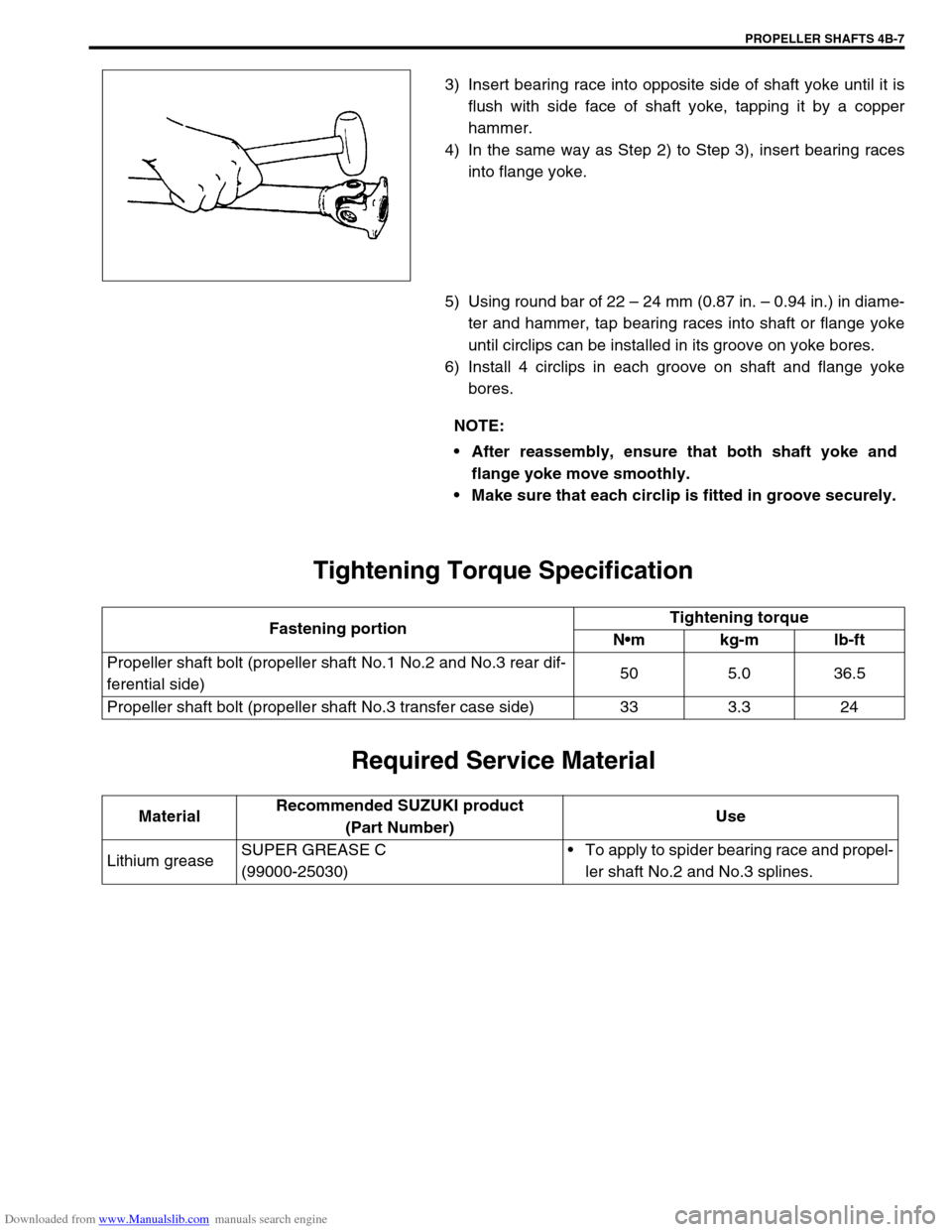
3) Insert bearing race into opposite side of shaft yoke until it is
flush with side face of shaft yoke, tapping it by a copper
hammer.
4) In the same way as Step 2) to Step 3), insert bearing races
into flange yoke.
5) Using round bar of 22 – 24 mm (0.87 in. – 0.94 in.) in diame-
ter and hammer, tap bearing races into shaft or flange yoke
until circlips can be installed in its groove on yoke bores.
6) Install 4 circlips in each groove on shaft and flange yoke
bores.
Tightening Torque Specification
Required Service Material
NOTE:
After reassembly, ensure that both shaft yoke and
flange yoke move smoothly.
Make sure that each circlip is fitted in groove securely.
Fastening portionTightening torque
Nm kg-m lb-ft
Propeller shaft bolt (propeller shaft No.1 No.2 and No.3 rear dif-
ferential side)50 5.0 36.5
Propeller shaft bolt (propeller shaft No.3 transfer case side) 33 3.3 24
MaterialRecommended SUZUKI product
(Part Number)Use
Lithium greaseSUPER GREASE C
(99000-25030)To apply to spider bearing race and propel-
ler shaft No.2 and No.3 splines.
Page 267 of 687

Downloaded from www.Manualslib.com manuals search engine 5-6 BRAKES
Excessive pedal travel
(Pedal stroke too
large)Partial brake system failure Check brake systems and repair as
necessary.
Insufficient fluid in master cylinder reservoirs Fill reservoirs with approved brake
fluid.
Check for leaks and air in brake
systems.
Check warning light. Bleed system
if required.
Air in system (pedal soft/spongy) Bleed system.
Rear brake system not adjusted (malfunctioning
auto adjusting mechanism)Repair auto adjusting mechanism.
Adjust rear brakes.
Bent brake shoes Replace brake shoes.
Worn rear brake shoes Replace brake shoes.
Dragging brakes (A
very light drag is
present in all disc
brakes immediately
after pedal is released)Master cylinder pistons not returning correctly Repair master cylinder.
Restricted brake tubes or hoses Check for soft hoses or damaged
tubes and replace with new hoses
and/or new brake tubes.
Incorrect parking brake adjustment on rear
brakesCheck and adjust to correct specifi-
cations.
Weakened or broken return springs in the brake Replace.
Sluggish parking-brake cables or linkage Repair or replace.
Wheel cylinder or caliper piston sticking Repair as necessary.
Malfunctioning ABS, if equipped with ABS Check system and replace as nec-
essary.
Pedal pulsation (Pedal
pulsates when
depressed for brak-
ing.) Damaged or loose wheel bearings Replace wheel bearings.
Distorted steering knuckle or rear axle shafts Replace knuckle or rear axle shaft.
Excessive disc lateral runout Check per instructions. If not within
specifications, replace or machine
the disc.
Parallelism not within specifications Check per instructions. If not with
specifications, replace or machine
the disc.
Rear drums out of round. Check runout.
Repair or replace drum as neces-
sary.
Braking noise
Glazed shoe linings, or foreign matters stuck to
liningsRepair or replace brake shoe.
Worn or distorted shoe linings Replace brake shoe (or pad).
Loose front wheel bearings Replace wheel bearing.
Distorted backing plates or loose mounting
boltsReplace or retighten securing bolts.
Brake warning light
turns on after engine
startParking brake applied Release parking brake and check
that brake warning light turns off.
Insufficient amount of brake fluid Add brake fluid.
Brake fluid leaking from brake line Investigate leaky point, correct it
and add brake fluid.
Brake warning light circuit faulty Repair circuit. Condition Possible Cause Correction
Page 288 of 687

Downloaded from www.Manualslib.com manuals search engine BRAKES 5-27
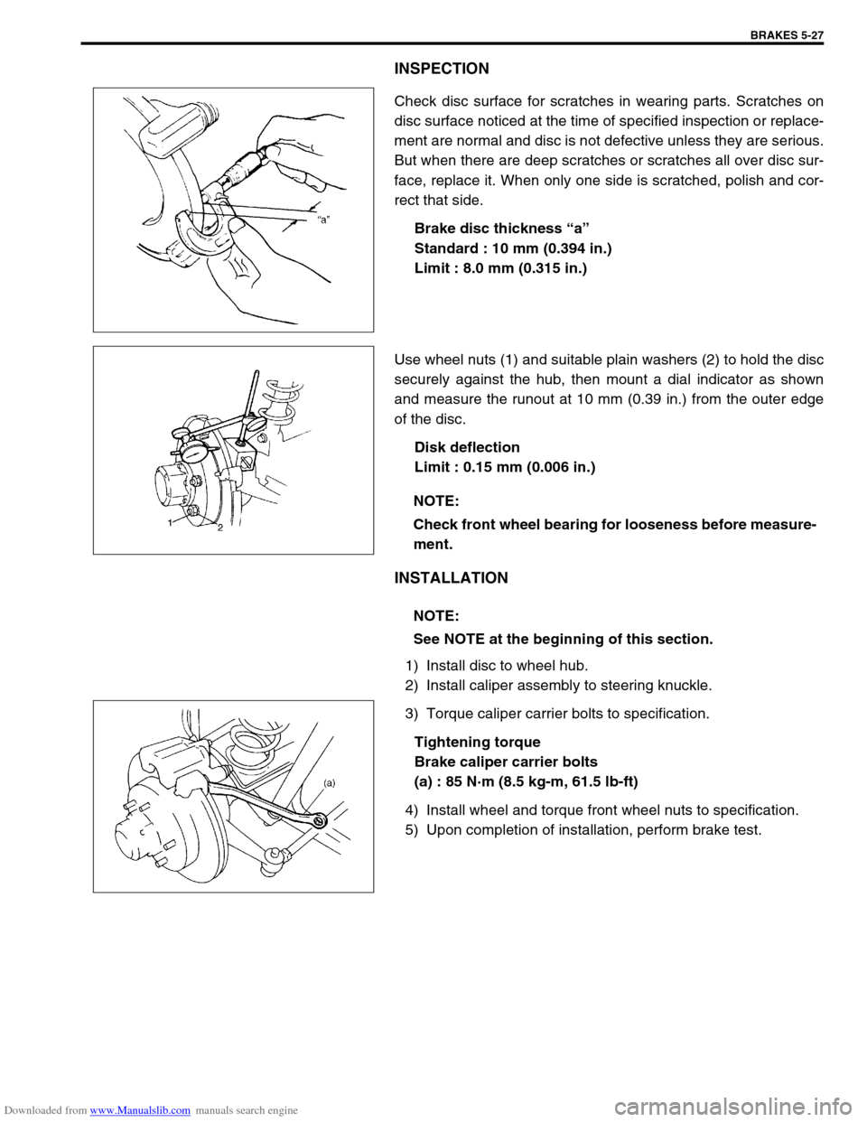
INSPECTION
Check disc surface for scratches in wearing parts. Scratches on
disc surface noticed at the time of specified inspection or replace-
ment are normal and disc is not defective unless they are serious.
But when there are deep scratches or scratches all over disc sur-
face, replace it. When only one side is scratched, polish and cor-
rect that side.
Brake disc thickness “a”
Standard : 10 mm (0.394 in.)
Limit : 8.0 mm (0.315 in.)
Use wheel nuts (1) and suitable plain washers (2) to hold the disc
securely against the hub, then mount a dial indicator as shown
and measure the runout at 10 mm (0.39 in.) from the outer edge
of the disc.
Disk deflection
Limit : 0.15 mm (0.006 in.)
INSTALLATION
1) Install disc to wheel hub.
2) Install caliper assembly to steering knuckle.
3) Torque caliper carrier bolts to specification.
Tightening torque
Brake caliper carrier bolts
(a) : 85 N·m (8.5 kg-m, 61.5 lb-ft)
4) Install wheel and torque front wheel nuts to specification.
5) Upon completion of installation, perform brake test.
NOTE:
Check front wheel bearing for looseness before measure-
ment.
NOTE:
See NOTE at the beginning of this section.
Page 289 of 687
Downloaded from www.Manualslib.com manuals search engine 5-28 BRAKES
CHECK FOR FRONT BRAKE AFTER INSTALLATION
Mount tires and make certain that they rotate smoothly, with a
force of less than 3.0 kg (6.6 Ib).
If tire rotation is heavy, check the following:
Piston, piston seal and cylinder slide bush of caliper for
installation.
Wheel bearings for breakage.
Disc for flatness (Improper flatness brings disc into contact
with lining during rotation and makes rotation heavy).
To check this, measure disc deflection.NOTE:
For above check the following must be observed.
Jack up front wheels, both right and left, off the
ground.
Shift transfer shift lever to 2H (rear wheel) position (if
equipped) and start engine for a few seconds then
stop.
Side figure shows outer periphery of tire.
Be careful not to depress brake pedal when checking
tire for rotation.
1. String
2. Spring measure
Page 296 of 687
Downloaded from www.Manualslib.com manuals search engine BRAKES 5-35
7) Using special tools, draw out rear axle shaft with brake back
plate.
Special tool
(A) : 09943-35511
(B) : 09942-15510
8) Remove wheel bearing retainer and wheel sensor ring (if
equipped with ABS), refer to “Rear Axle Shaft and Wheel
Bearing” in Section 3E.
9) Remove brake back plate from axle shaft.
INSTALLATION
1) Install wheel cylinder, and tighten wheel cylinder bolts to
specified torque. Refer to “Wheel Cylinder” in this section.
2) Install brake back plate (2) to axle shaft (1).
3) For installation procedure here after perform “Rear Axle
Shaft and Wheel Bearing” in Section 3E.
3. Wheel bearing
4. Retainer ring
Page 315 of 687

Downloaded from www.Manualslib.com manuals search engine 5-54 BRAKES
Tightening Torque Specifications
Required Service Material
Fastening partTightening torque
Nm kg-m lb-ft
Brake caliper carrier bolt 85 8.5 61.5
Brake caliper pin bolt 22 2.2 16.0
Front brake flexible hose bolt 23 2.3 17.0
Rear brake back plate nut 23 2.3 17.0
Master cylinder nut 13 1.3 9.5
Booster nut 13 1.3 9.5
Brake pipe 5-way 4-way joint bolt 11 1.1 8.0
Brake pipe flare nut 16 1.6 12.0
LSPV bolt/P valve bolt 25 2.5 18.0
Brake bleeder plugFront caliper 11 1.1 8.0
Rear wheel cylinder, LSPV 8 0.8 6.0
Wheel nut 95 9.5 69.0
Hose bracket bolt 11 1.1 8.0
Booster clevis nut 25 2.5 18.0
Stop light switch lock nut 6.5 0.65 4.7
Parking brake lever bolt 23 2.3 17.0
Wheel cylinder mounting bolt 9 0.9 6.5
Piston stopper bolt 10 1.0 7.5
LSPV adjust bolt 25 2.5 18.0
Material Recommended SUZUKI products Use
Brake fluid Indicated on reservoir tank cap or
described in owner’s manual of vehi-
cleTo fill master cylinder reservoir.
To clean and apply to inner parts of master
cylinder caliper and wheel cylinder when they
are disassembled.
Water tight sealant SEALING COMPOUND 366E
99000-31090To apply to mating surfaces of brake back
plate and rear wheel cylinder.
Sealant SUZUKI BOND NO. 1215
99000-31110To apply to mating surfaces of brake back
plate and rear axle housing.
To apply to mating surfaces of brake back
plate and rear wheel bearing retainer.
Page 339 of 687

Downloaded from www.Manualslib.com manuals search engine 5E-22 ANTILOCK BRAKE SYSTEM (ABS)
INSPECTION
Step Action Yes No
1 1) Disconnect the applicable sensor connector with ignition
switch OFF.
2) Measure resistance between sensor terminals.
Resistance of wheel speed sensor: 1.4 – 1.8 kΩ (at
20°C, 68°F)
3) Measure resistance between each terminal and body
ground.
Insulation resistance: 1MΩ or higher
Were measured resistance values in step 2) and 3) as spec-
ified? (See [A])Go to step 2. Replace sensor.
2 1) Ignition switch OFF.
2) Disconnect connector from ABS hydraulic unit / control
module assembly. (See [B])
3) Check for proper connection to ABS hydraulic unit / con-
trol module assembly at each sensor terminal.
4) If OK, then turn ignition switch ON and measure voltage
between sensor positive terminal of module connector
and body ground.
Is it 0V?Go to step 3. Sensor positive cir-
cuit shorted to
power.
3 1) Ignition switch OFF.
2) Connect connector to sensor.
3) Measure resistance between sensor terminals at mod-
ule connector.
4) Measure resistance between sensor positive terminal
and negative terminal of module connector, between
positive terminal and body ground.
Are measured resistance values within each specified range
described in above step 1?Go to step 4. Circuit open or
shorted to ground.
4 1) Remove wheel speed sensor.
2) Check sensor for damage or foreign material being
attached.
Is it in good condition? (See [C])Go to step 5. Clean or replace
sensor.
5 Check visually through wheel speed sensor installation hole
for following.
Ring serration (teeth) neither missing or damaged.
No foreign material being attached.
Ring not being eccentric.
Wheel bearing free from excessive play.
Are they in good condition? (See [D])Go to step 6. Clean, repair or
replace.
6 1) Install sensor to knuckle or axle housing.
2) Tighten sensor bolt to specified torque and check that
there is not any clearance between sensor and knuckle
or axle housing. (See [E])
Replace sensor if any.
Referring to “Front Wheel Speed Sensor” in this section,
check output voltage or waveform of sensor. Is proper out-
put voltage or waveform obtained?Substitute a known-
good ABS hydraulic
unit / control module
assembly and
recheck.Replace sensor and
recheck.