Page 236 of 687

Downloaded from www.Manualslib.com manuals search engine REAR SUSPENSION 3E-17
16) Upon completion of all jobs, depress brake pedal with about
30 kg (66 lbs) load over ten times so as to obtain proper
drum-to shoe clearance.
Adjust parking brake cable. (For adjustment, refer to “Parking
Brake Check and Adjustment” in Section 5.)
17) Tighten parking brake lever cover screws.
18) Check to ensure that brake drum is free from dragging and
proper braking is obtained. Then remove vehicle from hoist
and perform brake test (foot brake and parking brake).
19) Check each installed part for oil leakage.
Rear Axle Shaft Inner Oil Seal
REMOVAL
1) Remove rear axle shaft. For details, refer to “Rear Axle Shaft
and Wheel Bearing” in this section.
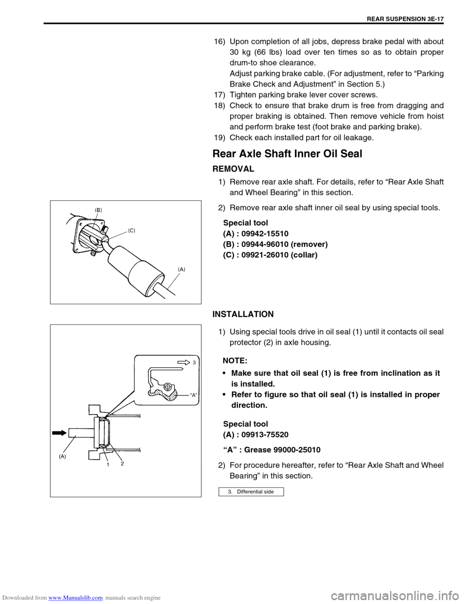
2) Remove rear axle shaft inner oil seal by using special tools.
Special tool
(A) : 09942-15510
(B) : 09944-96010 (remover)
(C) : 09921-26010 (collar)
INSTALLATION
1) Using special tools drive in oil seal (1) until it contacts oil seal
protector (2) in axle housing.
Special tool
(A) : 09913-75520
“A” : Grease 99000-25010
2) For procedure hereafter, refer to “Rear Axle Shaft and Wheel
Bearing” in this section.
NOTE:
Make sure that oil seal (1) is free from inclination as it
is installed.
Refer to figure so that oil seal (1) is installed in proper
direction.
3. Differential side
Page 237 of 687
Downloaded from www.Manualslib.com manuals search engine 3E-18 REAR SUSPENSION
Rear Axle Housing
REMOVAL
1) Hoist vehicle and remove wheels.
2) Remove rear axle shaft, refer to “Rear Axle Shaft and Wheel
Bearing” in this section.
3) Disconnect brake pipe (3) from flexible hose (1) and remove
E-ring (2).
4) Remove brake pipe clamps and pipes from axle housing.
5) For jobs hereafter, support rear axle housing (2) by using
floor jack (1) under axle housing (2).
6) Remove LSPV stay from axle housing (if equipped with
LSPV).
7) Before removing propeller shaft (2), give match marks (1) on
joint flange and propeller shaft (2) as shown.
Remove propeller shaft (2).
8) Remove differential carrier assembly (3).
9) Remove lateral rod (1).
Page 240 of 687

Downloaded from www.Manualslib.com manuals search engine REAR SUSPENSION 3E-21
11) Connect brake flexible hose (2) to bracket on axle housing
and secure it with E-ring (1).
12) Connect brake pipe to brake flexible hose and tighten brake
pipe flare nut to specified torque.
Tightening torque
Brake pipe flare nut
(a) : 16 N·m (1.6 kg-m, 11.5 lb-ft)
13) Clean mating surface of axle housing (2) (right & left) with
brake back plate and apply sealant as shown.
“B” : Sealant 99000-31090
14) Apply grease to axle shaft oil seals lip (1) (right & left) as
shown.
“A” : Grease 99000-25010
15) Install rear axle shafts, brake shoes, brake drums and
wheels. For details, refer to “Rear Axle Shaft and Wheel
Bearing” in this section.
16) Lower hoist.
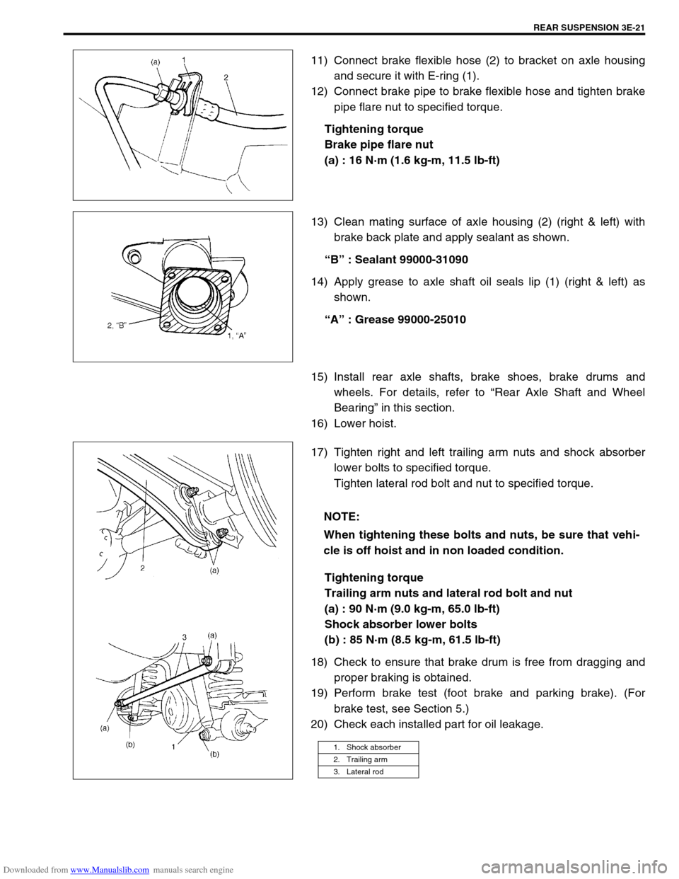
17) Tighten right and left trailing arm nuts and shock absorber
lower bolts to specified torque.
Tighten lateral rod bolt and nut to specified torque.
Tightening torque
Trailing arm nuts and lateral rod bolt and nut
(a) : 90 N·m (9.0 kg-m, 65.0 lb-ft)
Shock absorber lower bolts
(b) : 85 N·m (8.5 kg-m, 61.5 lb-ft)
18) Check to ensure that brake drum is free from dragging and
proper braking is obtained.
19) Perform brake test (foot brake and parking brake). (For
brake test, see Section 5.)
20) Check each installed part for oil leakage.
NOTE:
When tightening these bolts and nuts, be sure that vehi-
cle is off hoist and in non loaded condition.
1. Shock absorber
2. Trailing arm
3. Lateral rod
Page 242 of 687
Downloaded from www.Manualslib.com manuals search engine REAR SUSPENSION 3E-23
Special Tools
09913-75520 09913-85210 09924-74510 1) 09927-18411
Universal puller
Bearing installer Oil seal installer Bearing installer handle 2) 09921-57810
Bearing remover
09941-66010 09942-15510 09943-35511 or
09943-3551209944-96010
Bearing outer race
remover
Bump stopper wrench Sliding hammer Brake drum remover 09921-26010
Bearing outer race
remover collar
09951-16030 09951-26010
Bush remover Bush remover plate
Page 246 of 687

Downloaded from www.Manualslib.com manuals search engine WHEELS AND TIRES 3F-3
Replacement Wheels
Wheels must be replaced if they are bent, dented, have excessive
lateral or radial runout, leak air through welds, have elongated
bolt holes, if lug nuts won’t stay tight, or if they are heavily rusted.
Wheels with greater runout than shown in “How to Measure
Wheel Runout” may cause objectional vibrations.
Wheels for replacement must be equivalent to the originally
equipped wheels in load capacity, diameter, rim width, off-set and
mounting configuration. A wheel of improper size or type may
affect wheel and bearing life, brake cooling, speedometer / odom-
eter calibration, ground clearance to the body and chassis.
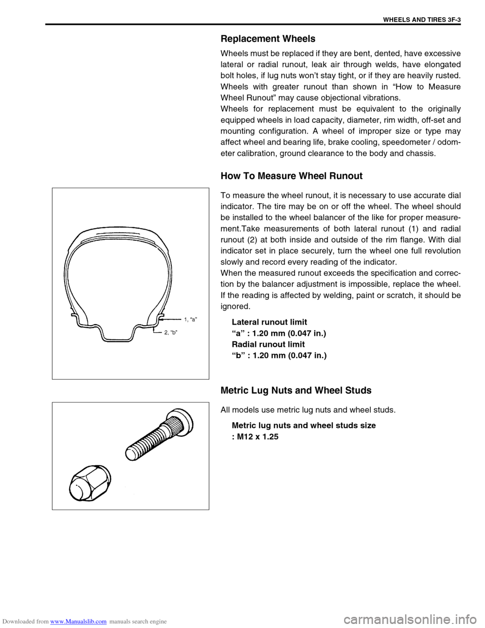
How To Measure Wheel Runout
To measure the wheel runout, it is necessary to use accurate dial
indicator. The tire may be on or off the wheel. The wheel should
be installed to the wheel balancer of the like for proper measure-
ment.Take measurements of both lateral runout (1) and radial
runout (2) at both inside and outside of the rim flange. With dial
indicator set in place securely, turn the wheel one full revolution
slowly and record every reading of the indicator.
When the measured runout exceeds the specification and correc-
tion by the balancer adjustment is impossible, replace the wheel.
If the reading is affected by welding, paint or scratch, it should be
ignored.
Lateral runout limit
“a” : 1.20 mm (0.047 in.)
Radial runout limit
“b” : 1.20 mm (0.047 in.)
Metric Lug Nuts and Wheel Studs
All models use metric lug nuts and wheel studs.
Metric lug nuts and wheel studs size
: M12 x 1.25
Page 251 of 687
Downloaded from www.Manualslib.com manuals search engine 3F-8 WHEELS AND TIRES
On-Vehicle Service
Wheel
REMOVAL
1) Loosen wheel nuts by approximately 180° (half a rotation).
2) Hoist vehicle.
3) Remove wheel.
INSTALLATION
Wheel nuts must be tightened in sequence and to proper torque
to avoid bending wheel or brake drum or disc as shown.
Tightening order
: “A”–“B”–“C”–“D”–“E”
Tightening torque
Wheel nuts
(a) : 95 N·m (9.5 kg-m, 69.0 lb-ft) CAUTION:
Never use heat to loosen tight wheel because application
of heat to wheel can shorten life of wheel and damage
wheel bearings.
NOTE:
Before installing wheels, remove any build-up of corro-
sion on wheel mounting surface and brake drum or disc
mounting surface by scraping and wire brushing. Install-
ing wheels without good metal-to-metal contact at
mounting surfaces can cause wheel nuts to loosen,
which can later allow wheel to come off while vehicle is
moving.
Page 255 of 687

Downloaded from www.Manualslib.com manuals search engine 4B-2 PROPELLER SHAFTS
General Description
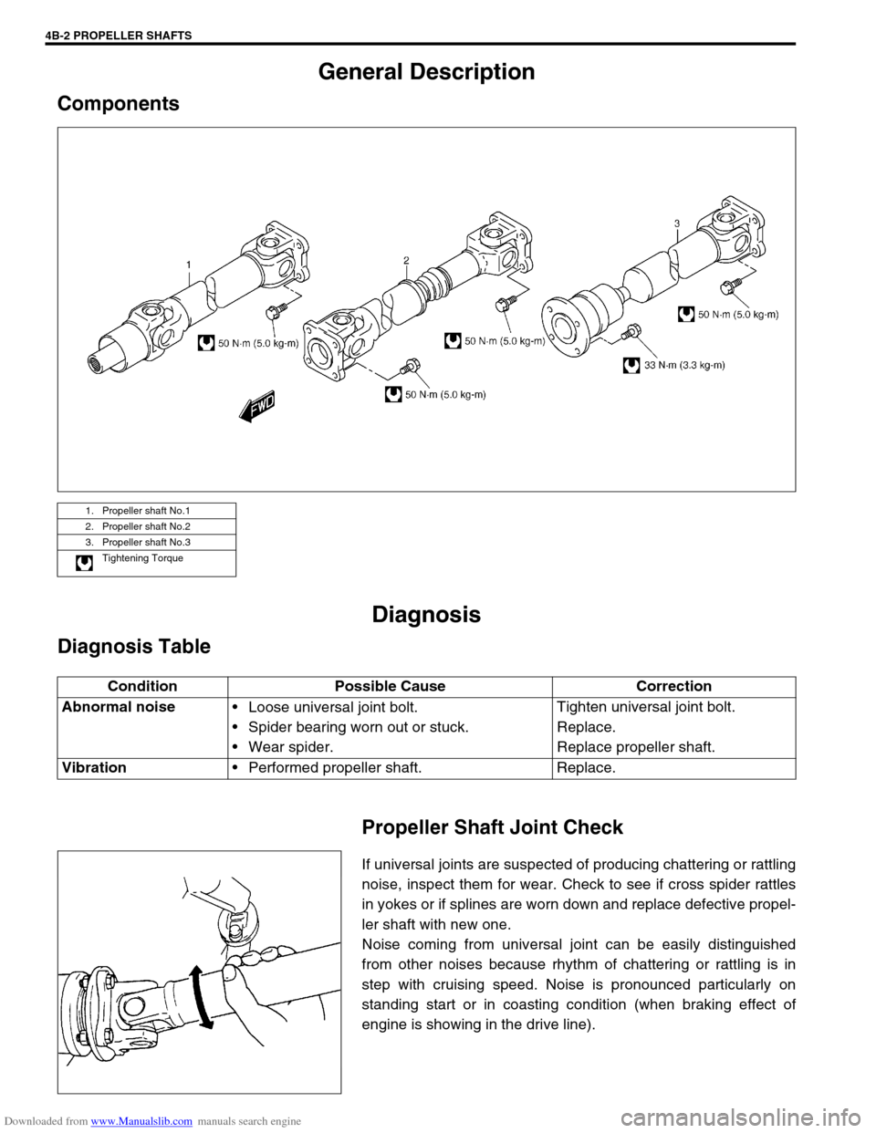
Components
Diagnosis
Diagnosis Table
Propeller Shaft Joint Check
If universal joints are suspected of producing chattering or rattling
noise, inspect them for wear. Check to see if cross spider rattles
in yokes or if splines are worn down and replace defective propel-
ler shaft with new one.
Noise coming from universal joint can be easily distinguished
from other noises because rhythm of chattering or rattling is in
step with cruising speed. Noise is pronounced particularly on
standing start or in coasting condition (when braking effect of
engine is showing in the drive line).
1. Propeller shaft No.1
2. Propeller shaft No.2
3. Propeller shaft No.3
Tightening Torque
Condition Possible Cause Correction
Abnormal noise
Loose universal joint bolt.
Spider bearing worn out or stuck.
Wear spider.Tighten universal joint bolt.
Replace.
Replace propeller shaft.
Vibration
Performed propeller shaft. Replace.
Page 258 of 687
Downloaded from www.Manualslib.com manuals search engine PROPELLER SHAFTS 4B-5
Universal Joint
DISASSEMBLY
1) Using special tool, remove 4 circlips (1).
Special tool
(A) : 09900-06108
2) Apply penetrate lubricant between bearing race outer diame-
ter and shaft yoke bore.
3) Using a set of special tool, push spider bearing race (1) out
3 – 4 mm (0.12 – 0.16 in.) from shaft yoke side face (2).
Special tool
(B) : 09926-48010
Pushed out value of bearing race from shaft yoke side
face
“a” : 3 – 4 mm (0.12 – 0.16 in.)
4) Tapping shaft yoke (2) with a hammer, remove bearing race
(1) from shaft yoke (2) completely.
5) Take out bearing race (1) on the opposite side of shaft yoke
(2) in the same way as shown.