2005 SUZUKI JIMNY length
[x] Cancel search: lengthPage 167 of 687

Downloaded from www.Manualslib.com manuals search engine 3C-14 STEERING WHEEL AND COLUMN
3) Take measurement “a” as shown.
If it is shorter than specified length, replace column assem-
bly (1) with new one.
Steering column assembly length
“a” : 733.2 – 734.8 mm (28.87 – 28.93 in.)
4) Check steering shaft joints and shaft for any damages such
as crack, breakage, malfunction or excessive play.
If anything is found faulty, replace as lower joint assembly or
column assembly.
5) Check steering shaft for smooth rotation.
If found defective, replace as column assembly.
6) Check steering shaft and column for bend, cracks or defor-
mation.
If found defective, replace.
7) Check steering column lower seal (1) for breakage or defor-
mation. If found defective, replace.
INSTALLATION
1) Be sure that front wheels and steering wheel are in straight
forward state.
2) If equipped, install shift (key) interlock cable to ignition
switch.
3) Apply sealant to the steering column lower bracket (shaded
section in the figure) and fit the steering column seal (1) to
the stepped part of the steering column lower bracket
securely.
“A” : Sealant 99000-31090
CAUTION:
After tightening steering column mounting bolts and
nuts shaft joint bolts should be tightened.
Page 171 of 687
Downloaded from www.Manualslib.com manuals search engine 3C-18 STEERING WHEEL AND COLUMN
Checking Steering Column for Accident Damage
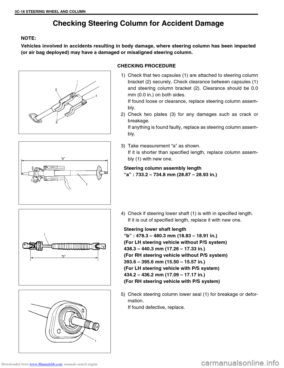
CHECKING PROCEDURE
1) Check that two capsules (1) are attached to steering column
bracket (2) securely. Check clearance between capsules (1)
and steering column bracket (2). Clearance should be 0.0
mm (0.0 in.) on both sides.
If found loose or clearance, replace steering column assem-
bly.
2) Check two plates (3) for any damages such as crack or
breakage.
If anything is found faulty, replace as steering column assem-
bly.
3) Take measurement “a” as shown.
If it is shorter than specified length, replace column assem-
bly (1) with new one.
Steering column assembly length
“a” : 733.2 – 734.8 mm (28.87 – 28.93 in.)
4) Check if steering lower shaft (1) is with in specified length.
If it is out of specified length, replace it with new one.
Steering lower shaft length
“b” : 478.3 – 480.3 mm (18.83 – 18.91 in.)
(For LH steering vehicle without P/S system)
438.3 – 440.3 mm (17.26 – 17.33 in.)
(For RH steering vehicle without P/S system)
393.6 – 395.6 mm (15.50 – 15.57 in.)
(For LH steering vehicle with P/S system)
434.2 – 436.2 mm (17.09 – 17.17 in.)
(For RH steering vehicle with P/S system)
5) Check steering column lower seal (1) for breakage or defor-
mation.
If found defective, replace. NOTE:
Vehicles involved in accidents resulting in body damage, where steering column has been impacted
(or air bag deployed) may have a damaged or misaligned steering column.
Page 210 of 687
Downloaded from www.Manualslib.com manuals search engine FRONT SUSPENSION 3D-37
INSTALLATION
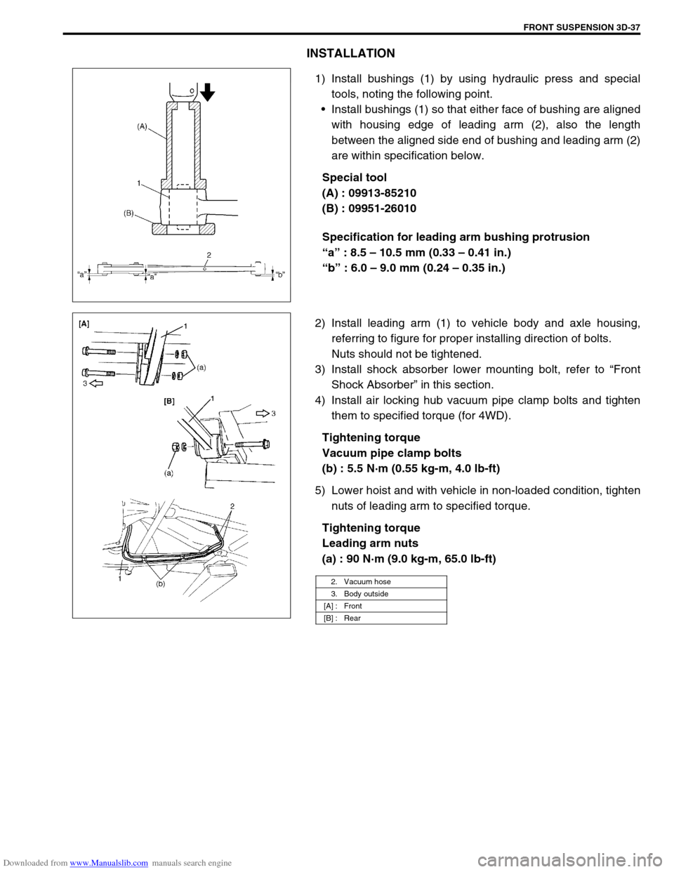
1) Install bushings (1) by using hydraulic press and special
tools, noting the following point.
Install bushings (1) so that either face of bushing are aligned
with housing edge of leading arm (2), also the length
between the aligned side end of bushing and leading arm (2)
are within specification below.
Special tool
(A) : 09913-85210
(B) : 09951-26010
Specification for leading arm bushing protrusion
“a” : 8.5 – 10.5 mm (0.33 – 0.41 in.)
“b” : 6.0 – 9.0 mm (0.24 – 0.35 in.)
2) Install leading arm (1) to vehicle body and axle housing,
referring to figure for proper installing direction of bolts.
Nuts should not be tightened.
3) Install shock absorber lower mounting bolt, refer to “Front
Shock Absorber” in this section.
4) Install air locking hub vacuum pipe clamp bolts and tighten
them to specified torque (for 4WD).
Tightening torque
Vacuum pipe clamp bolts
(b) : 5.5 N·m (0.55 kg-m, 4.0 lb-ft)
5) Lower hoist and with vehicle in non-loaded condition, tighten
nuts of leading arm to specified torque.
Tightening torque
Leading arm nuts
(a) : 90 N·m (9.0 kg-m, 65.0 lb-ft)
2. Vacuum hose
3. Body outside
[A] : Front
[B] : Rear
Page 231 of 687
Downloaded from www.Manualslib.com manuals search engine 3E-12 REAR SUSPENSION
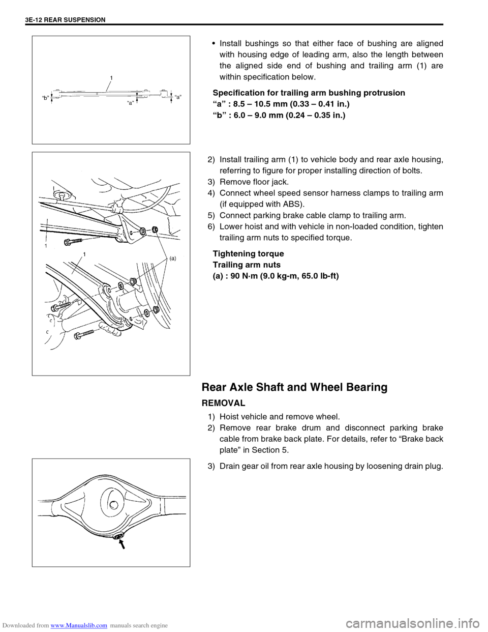
Install bushings so that either face of bushing are aligned
with housing edge of leading arm, also the length between
the aligned side end of bushing and trailing arm (1) are
within specification below.
Specification for trailing arm bushing protrusion
“a” : 8.5 – 10.5 mm (0.33 – 0.41 in.)
“b” : 6.0 – 9.0 mm (0.24 – 0.35 in.)
2) Install trailing arm (1) to vehicle body and rear axle housing,
referring to figure for proper installing direction of bolts.
3) Remove floor jack.
4) Connect wheel speed sensor harness clamps to trailing arm
(if equipped with ABS).
5) Connect parking brake cable clamp to trailing arm.
6) Lower hoist and with vehicle in non-loaded condition, tighten
trailing arm nuts to specified torque.
Tightening torque
Trailing arm nuts
(a) : 90 N·m (9.0 kg-m, 65.0 lb-ft)
Rear Axle Shaft and Wheel Bearing
REMOVAL
1) Hoist vehicle and remove wheel.
2) Remove rear brake drum and disconnect parking brake
cable from brake back plate. For details, refer to “Brake back
plate” in Section 5.
3) Drain gear oil from rear axle housing by loosening drain plug.
Page 234 of 687

Downloaded from www.Manualslib.com manuals search engine REAR SUSPENSION 3E-15
INSTALLATION
Install removed parts in reverse order of removal procedure, not-
ing the following.
1) Aligning serrations between new stud bolt(s) (1) and flange,
install new stud bolt(s) (1) by tightening nut (2) as shown.
2) Press-fit wheel bearing (1) and retainer ring (2) as shown.
3) For vehicle with ABS, press-fit new sensor rotor as shown.
4) Inspect axle shaft length.
Rear axle shaft length
“a” : 775.5 mm (30.5 in.) (left side),
559.5 mm (22.0 in.) (right side)
5) Apply grease to axle shaft oil seal lip (1) as shown.
“A” : Grease 99000-25010
6) Apply sealant to mating surface of axle housing (2) with
brake back plate.
“B” : Sealant 99000-31110
3. Washer
4. Flange of axle shaft
NOTE:
Use care not to cause any damage to outside of
retainer ring (2).
Refer to figure so that wheel bearing (1) is installed in
proper direction.
NOTE:
Use care not to cause any damage to outside of retainer
ring (2).
[A]: Vehicle without ABS
[B]: Vehicle with ABS
NOTE:
Make sure to remove old sealant before applying it anew.
Page 266 of 687

Downloaded from www.Manualslib.com manuals search engine BRAKES 5-5
Diagnosis Table
Condition Possible Cause Correction
Not enough braking
forceBrake oil leakage from brake lines Locate leaking point and repair.
Brake disc or pads stained with oil Clean or replace.
Overheated brakes Determine cause and repair.
Poor contact of shoes on brake drum Repair for proper contact.
Brake shoes linings stained with oil or wet with
waterReplace.
Badly worn brake shoe linings Replace.
Defective wheel cylinders Repair or replace.
Malfunctioning caliper assembly Repair or replace.
Air in system Bleed system.
Maladjusted sensor spring length of LSPV Check or adjust.
Broken sensor spring of LSPV Replace.
Defective collar of LSPV Replace.
Malfunctioning ABS (Antilock brake system), if
equippedCheck system and replace as nec-
essary.
Brake pull (Brakes not
working in unison)Pad or shoe linings are wet with water or
stained with oil in some brakesReplace.
Drum-to-shoe clearance out of adjustment in
some brakes (Malfunctioning auto adjusting
mechanism)Check for inoperative auto adjusting
mechanism.
Drum is out of round in some brakes Replace.
Wheel tires are inflated unequally Inflate equally.
Malfunctioning wheel cylinders Repair or replace.
Disturbed front wheel alignment Adjust as prescribed.
Unmatched tires on same axle Tires with approximately the same
amount of tread should be used on
the same axle.
Restricted brake tubes or hoses Check for soft hoses and damaged
lines.
Replace with new hoses and new
double-walled steel brake tubing.
Malfunctioning caliper assembly Check for stuck or sluggish pistons
and proper lubrication of caliper
slide bush.
Loose suspension parts Caliper should slide.
Check all suspension mountings.
Loose calipers Check and torque bolts to specifica-
tions.
Noise (high pitched
squeak without brake
applied)Front lining worn out Replace brake pads.
Rear brake locked pre-
maturelyMaladjusted sensor spring length of LSPV Check or adjust.
Malfunctioning LSPV assembly Replace assembly.
Brake locked
(For vehicles
equipped with ABS)Malfunctioning ABS, if equipped Check system and replace as nec-
essary.
Page 270 of 687
Downloaded from www.Manualslib.com manuals search engine BRAKES 5-9
Excessive Pedal Travel Check
1) Start engine.
2) Depress brake pedal a few times.
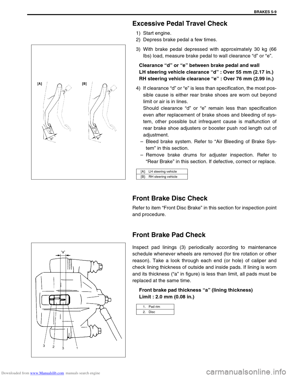
3) With brake pedal depressed with approximately 30 kg (66
Ibs) load, measure brake pedal to wall clearance “d” or “e”.
Clearance “d” or “e” between brake pedal and wall
LH steering vehicle clearance “d” : Over 55 mm (2.17 in.)
RH steering vehicle clearance “e” : Over 76 mm (2.99 in.)
4) If clearance “d” or “e” is less than specification, the most pos-
sible cause is either rear brake shoes are worn out beyond
limit or air is in lines.
Should clearance “d” or “e” remain less than specification
even after replacement of brake shoes and bleeding of sys-
tem, other possible but infrequent cause is malfunction of
rear brake shoe adjusters or booster push rod length out of
adjustment.
–Bleed brake system. Refer to “Air Bleeding of Brake Sys-
tem” in this section.
–Remove brake drums for adjuster inspection. Refer to
“Rear Brake” in this section. If defective, correct or replace.
Front Brake Disc Check
Refer to item “Front Disc Brake” in this section for inspection point
and procedure.
Front Brake Pad Check
Inspect pad linings (3) periodically according to maintenance
schedule whenever wheels are removed (for tire rotation or other
reason). Take a look through each end (or hole) of caliper and
check lining thickness of outside and inside pads. If lining is worn
and its thickness (“a” in figure) is less than limit, all pads must be
replaced at the same time.
Front brake pad thickness “a” (lining thickness)
Limit : 2.0 mm (0.08 in.)
[A]: LH steering vehicle
[B]: RH steering vehicle
1. Pad rim
2. Disc
Page 298 of 687
Downloaded from www.Manualslib.com manuals search engine BRAKES 5-37
INSTALLATION
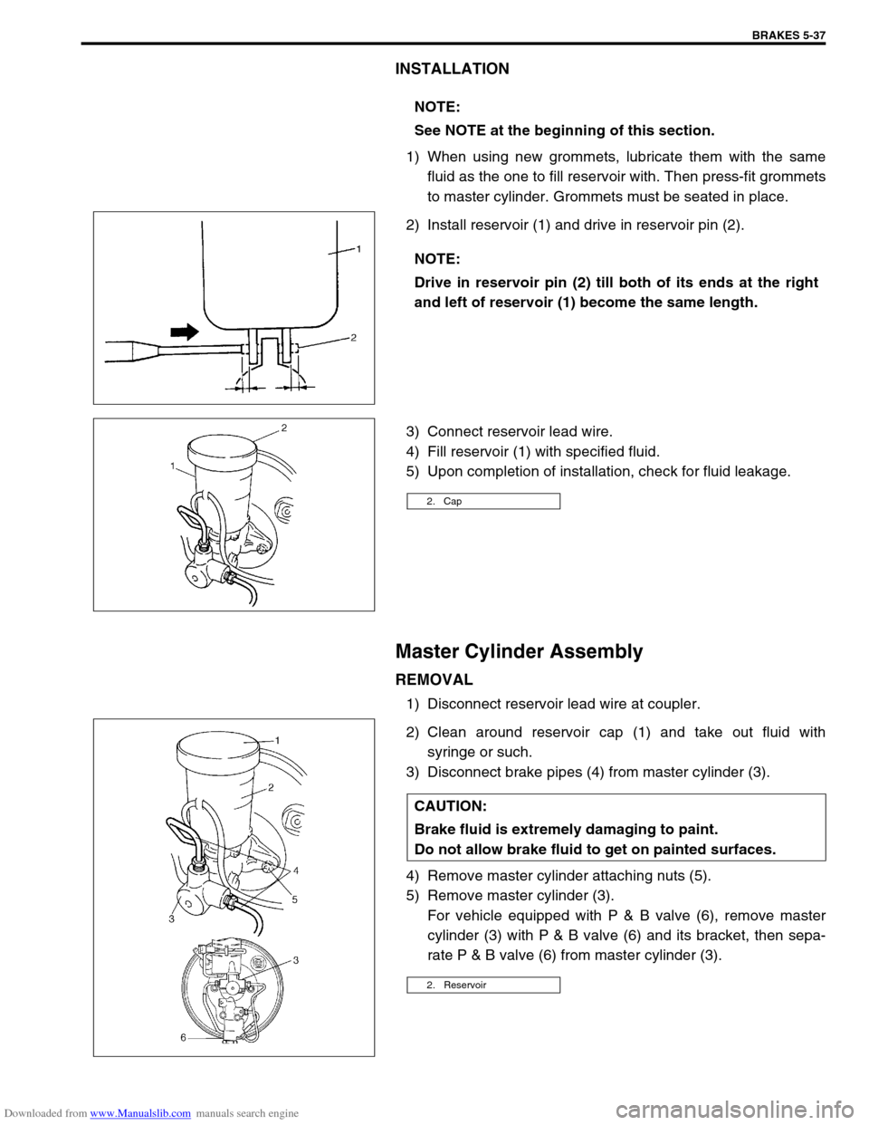
1) When using new grommets, lubricate them with the same
fluid as the one to fill reservoir with. Then press-fit grommets
to master cylinder. Grommets must be seated in place.
2) Install reservoir (1) and drive in reservoir pin (2).
3) Connect reservoir lead wire.
4) Fill reservoir (1) with specified fluid.
5) Upon completion of installation, check for fluid leakage.
Master Cylinder Assembly
REMOVAL
1) Disconnect reservoir lead wire at coupler.
2) Clean around reservoir cap (1) and take out fluid with
syringe or such.
3) Disconnect brake pipes (4) from master cylinder (3).
4) Remove master cylinder attaching nuts (5).
5) Remove master cylinder (3).
For vehicle equipped with P & B valve (6), remove master
cylinder (3) with P & B valve (6) and its bracket, then sepa-
rate P & B valve (6) from master cylinder (3). NOTE:
See NOTE at the beginning of this section.
NOTE:
Drive in reservoir pin (2) till both of its ends at the right
and left of reservoir (1) become the same length.
2. Cap
CAUTION:
Brake fluid is extremely damaging to paint.
Do not allow brake fluid to get on painted surfaces.
2. Reservoir