Page 304 of 687
Downloaded from www.Manualslib.com manuals search engine BRAKES 5-43
LSPV Assembly
INSPECTION AND ADJUSTMENT
1) Confirm the following before inspection and adjustment.
Fuel tank is filled with fuel fully.
Vehicle is equipped with spare tire, tools, jack and jack han-
dle.
Vehicle is free from any other load.
Place it on level floor.
2) Push up LSPV lever with finger till it stops and measure
length of coil spring (“a” in figure).
3) Spring length “a” should be as specified.
Spring length “a”
147 mm (5.79 in.)
4) If it isn’t, adjust it to specification by changing stay position
as shown in figure. After adjustment, tighten bolt to specified
torque.
Tightening torque
LSPV adjust bolt
(a) : 25 N·m (2.5 kg-m, 18.0 lb-ft)
NOTE:
Check to make sure that LSPV body and brake pipe joints
are free from fluid leakage. Replace defective parts, if
any.
Page 307 of 687
Downloaded from www.Manualslib.com manuals search engine 5-46 BRAKES
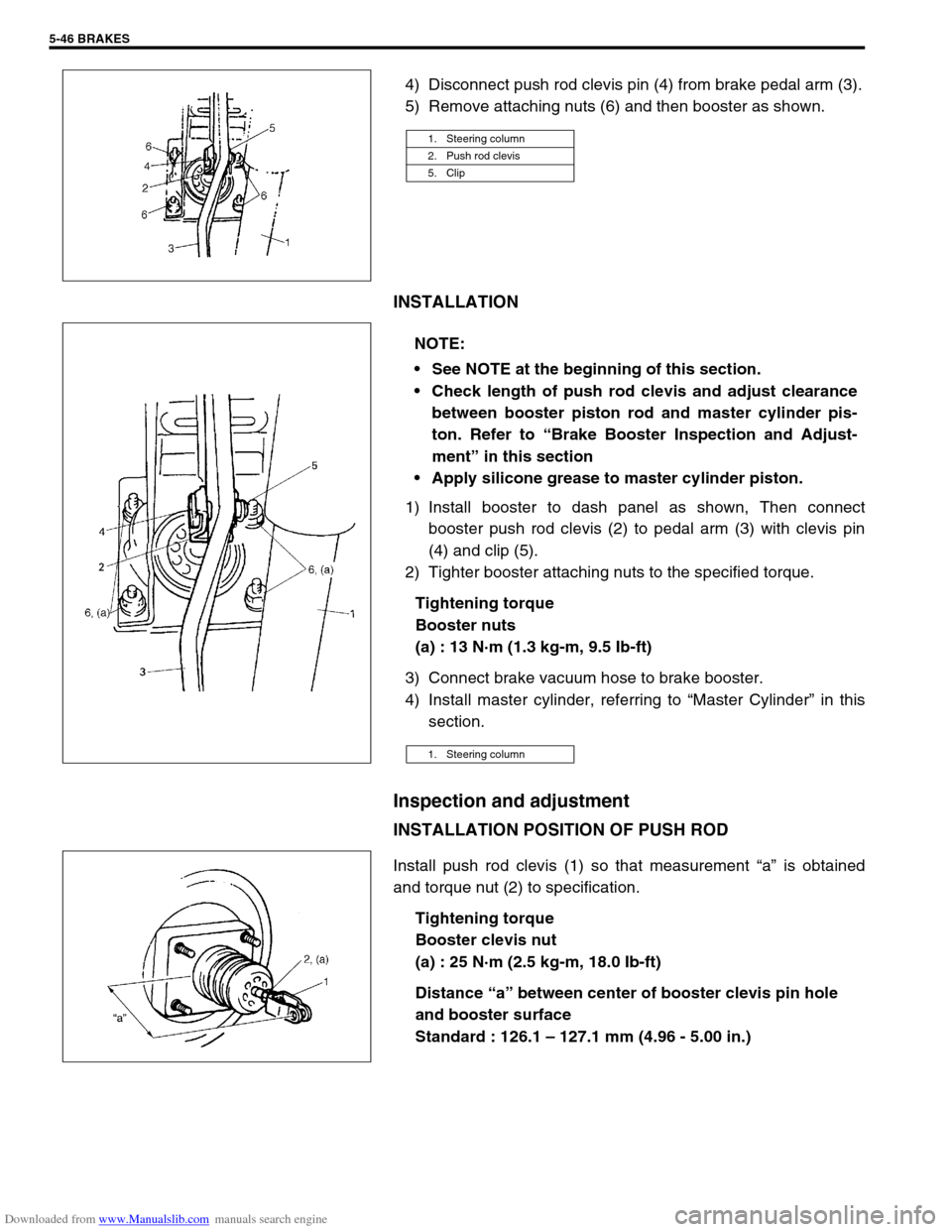
4) Disconnect push rod clevis pin (4) from brake pedal arm (3).
5) Remove attaching nuts (6) and then booster as shown.
INSTALLATION
1) Install booster to dash panel as shown, Then connect
booster push rod clevis (2) to pedal arm (3) with clevis pin
(4) and clip (5).
2) Tighter booster attaching nuts to the specified torque.
Tightening torque
Booster nuts
(a) : 13 N·m (1.3 kg-m, 9.5 Ib-ft)
3) Connect brake vacuum hose to brake booster.
4) Install master cylinder, referring to “Master Cylinder” in this
section.
Inspection and adjustment
INSTALLATION POSITION OF PUSH ROD
Install push rod clevis (1) so that measurement “a” is obtained
and torque nut (2) to specification.
Tightening torque
Booster clevis nut
(a) : 25 N·m (2.5 kg-m, 18.0 Ib-ft)
Distance “a” between center of booster clevis pin hole
and booster surface
Standard : 126.1 – 127.1 mm (4.96 - 5.00 in.)
1. Steering column
2. Push rod clevis
5. Clip
NOTE:
See NOTE at the beginning of this section.
Check length of push rod clevis and adjust clearance
between booster piston rod and master cylinder pis-
ton. Refer to “Brake Booster Inspection and Adjust-
ment” in this section
Apply silicone grease to master cylinder piston.
1. Steering column
Page 308 of 687
Downloaded from www.Manualslib.com manuals search engine BRAKES 5-47
CLEARANCE BETWEEN BOOSTER PISTON ROD AND
MASTER CYLINDER PISTON
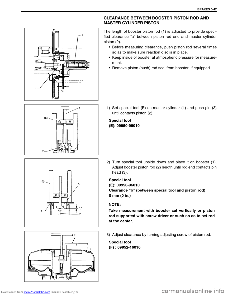
The length of booster piston rod (1) is adjusted to provide speci-
fied clearance “a” between piston rod end and master cylinder
piston (2).
Before measuring clearance, push piston rod several times
so as to make sure reaction disc is in place.
Keep inside of booster at atmospheric pressure for measure-
ment.
Remove piston (push) rod seal from booster, if equipped.
1) Set special tool (E) on master cylinder (1) and push pin (3)
until contacts piston (2).
Special tool
(E): 09950-96010
2) Turn special tool upside down and place it on booster (1).
Adjust booster piston rod (2) length until rod end contacts pin
head (3).
Special tool
(E): 09950-96010
Clearance “b” (between special tool and piston rod)
0 mm (0 in.)
3) Adjust clearance by turning adjusting screw of piston rod.
Special tool
(F) : 09952-16010
NOTE:
Take measurement with booster set vertically or piston
rod supported with screw driver or such so as to set rod
at the center.
Page 511 of 687
Downloaded from www.Manualslib.com manuals search engine 6A1-30 ENGINE MECHANICAL (M13 ENGINE)
12) Remove crankshaft pulley bolt.
To lock crankshaft pulley (1), use special tool with it as
shown in figure.
Special tool
(A) : 09917-68221
13) Remove crankshaft pulley (1).
If it is hard to remove, use special tools as shown in figure.
If bolts of special tool are too long, replace them with those
of suitable length.
Special tool
(A) : 09944-36011
(B) : 09926-58010
14) Remove oil pan referring to “Oil Pan and Oil Pump Strainer”
in this section.
15) Remove cylinder head cover referring to “Cylinder Head
Cover” in this section.
16) Disconnect CMP sensor coupler (1) and release its harness
clamps.
17) Remove water outlet pipe (2).
18) Remove timing chain cover (3).
CLEANING
Clean sealing surface on timing chain cover, cylinder block
and cylinder head.
Remove oil, old sealant and dust from sealing surface.
Page 534 of 687
Downloaded from www.Manualslib.com manuals search engine ENGINE MECHANICAL (M13 ENGINE) 6A1-53
INSPECTION
Valve Guides
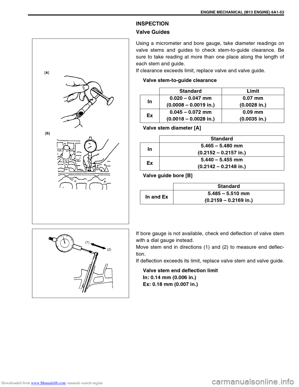
Using a micrometer and bore gauge, take diameter readings on
valve stems and guides to check stem-to-guide clearance. Be
sure to take reading at more than one place along the length of
each stem and guide.
If clearance exceeds limit, replace valve and valve guide.
Valve stem-to-guide clearance
Valve stem diameter [A]
Valve guide bore [B]
If bore gauge is not available, check end deflection of valve stem
with a dial gauge instead.
Move stem end in directions (1) and (2) to measure end deflec-
tion.
If deflection exceeds its limit, replace valve stem and valve guide.
Valve stem end deflection limit
In: 0.14 mm (0.006 in.)
Ex: 0.18 mm (0.007 in.)Standard Limit
In0.020 – 0.047 mm
(0.0008 – 0.0019 in.)0.07 mm
(0.0028 in.)
Ex0.045 – 0.072 mm
(0.0018 – 0.0028 in.)0.09 mm
(0.0035 in.)
Standard
In5.465 – 5.480 mm
(0.2152 – 0.2157 in.)
Ex5.440 – 5.455 mm
(0.2142 – 0.2148 in.)
Standard
In and Ex5.485 – 5.510 mm
(0.2159 – 0.2169 in.)
Page 538 of 687
Downloaded from www.Manualslib.com manuals search engine ENGINE MECHANICAL (M13 ENGINE) 6A1-57
Valve Springs
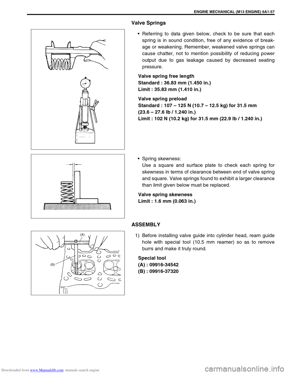
Referring to data given below, check to be sure that each
spring is in sound condition, free of any evidence of break-
age or weakening. Remember, weakened valve springs can
cause chatter, not to mention possibility of reducing power
output due to gas leakage caused by decreased seating
pressure.
Valve spring free length
Standard : 36.83 mm (1.450 in.)
Limit : 35.83 mm (1.410 in.)
Valve spring preload
Standard : 107 – 125 N (10.7 – 12.5 kg) for 31.5 mm
(23.6 – 27.6 lb / 1.240 in.)
Limit : 102 N (10.2 kg) for 31.5 mm (22.9 lb / 1.240 in.)
Spring skewness:
Use a square and surface plate to check each spring for
skewness in terms of clearance between end of valve spring
and square. Valve springs found to exhibit a larger clearance
than limit given below must be replaced.
Valve spring skewness
Limit : 1.6 mm (0.063 in.)
ASSEMBLY
1) Before installing valve guide into cylinder head, ream guide
hole with special tool (10.5 mm reamer) so as to remove
burrs and make it truly round.
Special tool
(A) : 09916-34542
(B) : 09916-37320
Page 563 of 687
Downloaded from www.Manualslib.com manuals search engine 6A1-82 ENGINE MECHANICAL (M13 ENGINE)
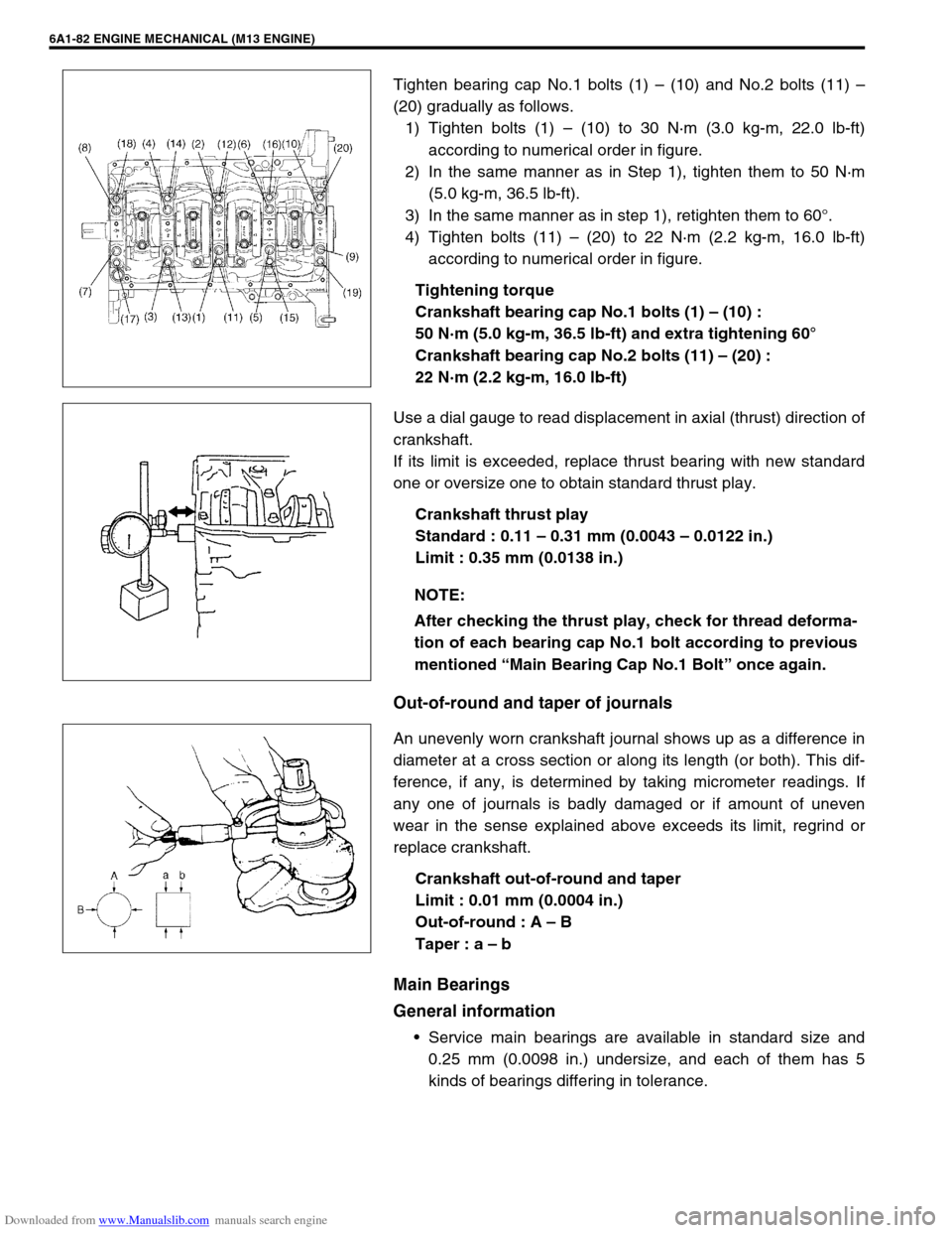
Tighten bearing cap No.1 bolts (1) – (10) and No.2 bolts (11) –
(20) gradually as follows.
1) Tighten bolts (1) – (10) to 30 N·m (3.0 kg-m, 22.0 lb-ft)
according to numerical order in figure.
2) In the same manner as in Step 1), tighten them to 50 N·m
(5.0 kg-m, 36.5 lb-ft).
3) In the same manner as in step 1), retighten them to 60°.
4) Tighten bolts (11) – (20) to 22 N·m (2.2 kg-m, 16.0 lb-ft)
according to numerical order in figure.
Tightening torque
Crankshaft bearing cap No.1 bolts (1) – (10) :
50 N·m (5.0 kg-m, 36.5 lb-ft) and extra tightening 60°
Crankshaft bearing cap No.2 bolts (11) – (20) :
22 N·m (2.2 kg-m, 16.0 lb-ft)
Use a dial gauge to read displacement in axial (thrust) direction of
crankshaft.
If its limit is exceeded, replace thrust bearing with new standard
one or oversize one to obtain standard thrust play.
Crankshaft thrust play
Standard : 0.11 – 0.31 mm (0.0043 – 0.0122 in.)
Limit : 0.35 mm (0.0138 in.)
Out-of-round and taper of journals
An unevenly worn crankshaft journal shows up as a difference in
diameter at a cross section or along its length (or both). This dif-
ference, if any, is determined by taking micrometer readings. If
any one of journals is badly damaged or if amount of uneven
wear in the sense explained above exceeds its limit, regrind or
replace crankshaft.
Crankshaft out-of-round and taper
Limit : 0.01 mm (0.0004 in.)
Out-of-round : A – B
Taper : a – b
Main Bearings
General information
Service main bearings are available in standard size and
0.25 mm (0.0098 in.) undersize, and each of them has 5
kinds of bearings differing in tolerance.
NOTE:
After checking the thrust play, check for thread deforma-
tion of each bearing cap No.1 bolt according to previous
mentioned “Main Bearing Cap No.1 Bolt” once again.
Page 666 of 687
Downloaded from www.Manualslib.com manuals search engine CRANKING SYSTEM 6G-7
Specifications
Voltage 12 volts
Output 0.9 kW 1.2 kW
Rating 30 seconds
Direction of rotation Clockwise as viewed from pinion side
Brush length 12.3 mm (0.48 in.) 12.3 mm (0.48 in.)
Number of pinion teeth 8
Performance Condition Guarantee
Around at
20° C (68 °F)No load characteristic 11.0 V90 A maximum
2,800 rpm minimum90 A maximum
2,500 rpm minimum
Load characteristic8.0 V
200 A4.8 N·m (0.48 kg-m,
3.5 lb-ft) minimum
1,260 rpm minimum–
7.5 V
300 A–10.5 N·m (1.05 kg-m,
7.6 lb-ft) minimum
880 rpm minimum
Locked rotor current3.5 V550 A maximum
12.2 N·m (1.22 kg-m,
8.8 lb-ft) minimum–
4.0 V–760 A maximum
19.5 N·m (1.95 kg-m,
14.1 lb-ft) minimum
Magnetic switch operating voltage 8 volts maximum