Page 475 of 687
Downloaded from www.Manualslib.com manuals search engine 6-118 ENGINE GENERAL INFORMATION AND DIAGNOSIS
INSPECTION
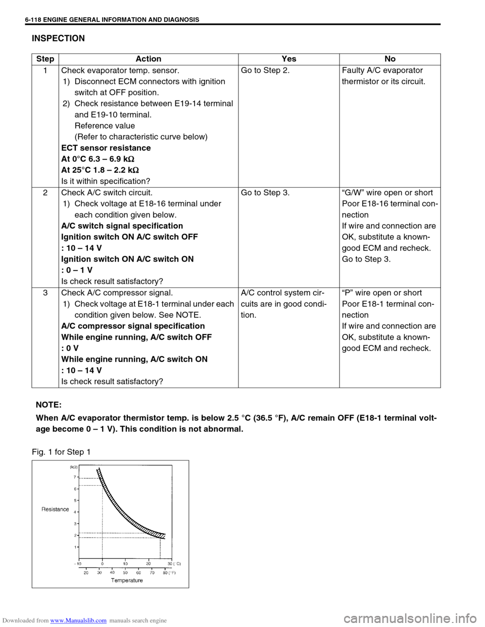
Fig. 1 for Step 1Step Action Yes No
1 Check evaporator temp. sensor.
1) Disconnect ECM connectors with ignition
switch at OFF position.
2) Check resistance between E19-14 terminal
and E19-10 terminal.
Reference value
(Refer to characteristic curve below)
ECT sensor resistance
At 0°C 6.3 – 6.9 k
Ω
ΩΩ Ω
At 25°C 1.8 – 2.2 k
Ω
ΩΩ Ω
Is it within specification?Go to Step 2. Faulty A/C evaporator
thermistor or its circuit.
2 Check A/C switch circuit.
1) Check voltage at E18-16 terminal under
each condition given below.
A/C switch signal specification
Ignition switch ON A/C switch OFF
: 10 – 14 V
Ignition switch ON A/C switch ON
: 0 – 1 V
Is check result satisfactory?Go to Step 3.“G/W” wire open or short
Poor E18-16 terminal con-
nection
If wire and connection are
OK, substitute a known-
good ECM and recheck.
Go to Step 3.
3 Check A/C compressor signal.
1) Check voltage at E18-1 terminal under each
condition given below. See NOTE.
A/C compressor signal specification
While engine running, A/C switch OFF
: 0 V
While engine running, A/C switch ON
: 10 – 14 V
Is check result satisfactory?A/C control system cir-
cuits are in good condi-
tion.“P” wire open or short
Poor E18-1 terminal con-
nection
If wire and connection are
OK, substitute a known-
good ECM and recheck.
NOTE:
When A/C evaporator thermistor temp. is below 2.5 °C (36.5 °F), A/C remain OFF (E18-1 terminal volt-
age become 0 – 1 V). This condition is not abnormal.
Page 476 of 687
Downloaded from www.Manualslib.com manuals search engine ENGINE GENERAL INFORMATION AND DIAGNOSIS 6-119
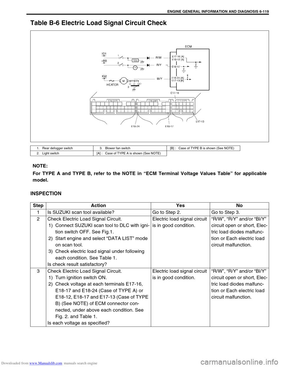
Table B-6 Electric Load Signal Circuit Check
INSPECTION
1. Rear defogger switch 3. Blower fan switch [B] : Case of TYPE B is shown (See NOTE)
2. Light switch [A] : Case of TYPE A is shown (See NOTE)
NOTE:
For TYPE A and TYPE B, refer to the NOTE in “ECM Terminal Voltage Values Table” for applicable
model.
Step Action Yes No
1 Is SUZUKI scan tool available? Go to Step 2. Go to Step 3.
2 Check Electric Load Signal Circuit.
1) Connect SUZUKI scan tool to DLC with igni-
tion switch OFF. See Fig.1.
2) Start engine and select “DATA LIST” mode
on scan tool.
3) Check electric load signal under following
each condition. See Table 1.
Is check result satisfactory?Electric load signal circuit
is in good condition.“R/W”, “R/Y” and/or “Bl/Y”
circuit open or short, Elec-
tric load diodes malfunc-
tion or Each electric load
circuit malfunction.
3 Check Electric Load Signal Circuit.
1) Turn ignition switch ON.
2) Check voltage at each terminals E17-16,
E18-17 and E18-24 (Case of TYPE A) or
E18-12, E18-17 and E17-13 (Case of TYPE
B) (See NOTE) of ECM connector con-
nected, under above each condition. See
Fig. 2. and Table 1.
Is each voltage as specified?Electric load signal circuit
is in good condition.“R/W”, “R/Y” and/or “Bl/Y”
circuit open or short, Elec-
tric load diodes malfunc-
tion or Each electric load
circuit malfunction.
Page 479 of 687
Downloaded from www.Manualslib.com manuals search engine 6-122 ENGINE GENERAL INFORMATION AND DIAGNOSIS
[A] Fig. 1 for Step 1 / [B] Fig. 2 for Step 3
Fig. 3 for Step 44 Check A/C Condenser Fan (1).
1) Turn ignition switch OFF.
2) Disconnect fan motor connector (2).
3) Check for proper connection to motor at “R/Bl” and “B”
terminals.
4) If OK, connect battery to motor and check for operation.
See Fig. 3.
Is it in good condition?“R”, “R/Bl” or “B” circuit
open.Replace A/C
condenser fan
motor. Step Action Yes No
Page 480 of 687
Downloaded from www.Manualslib.com manuals search engine ENGINE GENERAL INFORMATION AND DIAGNOSIS 6-123
Special Tool
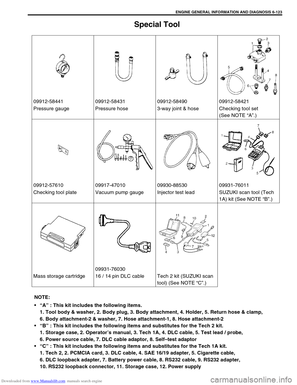
09912-58441 09912-58431 09912-58490 09912-58421
Pressure gauge Pressure hose 3-way joint & hose Checking tool set
(See NOTE “A”.)
09912-57610 09917-47010 09930-88530 09931-76011
Checking tool plate Vacuum pump gauge Injector test lead SUZUKI scan tool (Tech
1A) kit (See NOTE “B”.)
09931-76030
Mass storage cartridge 16 / 14 pin DLC cable Tech 2 kit (SUZUKI scan
tool) (See NOTE “C”.)
NOTE:
“A” : This kit includes the following items.
1. Tool body & washer, 2. Body plug, 3. Body attachment, 4. Holder, 5. Return hose & clamp,
6. Body attachment-2 & washer, 7. Hose attachment-1, 8. Hose attachment-2
“B” : This kit includes the following items and substitutes for the Tech 2 kit.
1. Storage case, 2. Operator’s manual, 3. Tech 1A, 4. DLC cable, 5. Test lead / probe,
6. Power source cable, 7. DLC cable adaptor, 8. Self–test adaptor
“C” : This kit includes the following items and substitutes for the Tech 1A kit.
1. Tech 2, 2. PCMCIA card, 3. DLC cable, 4. SAE 16/19 adapter, 5. Cigarette cable,
6. DLC loopback adapter, 7. Battery power cable, 8. RS232 cable, 9. RS232 adapter,
10. RS232 loopback connector, 11. Storage case, 12. Power supply
Page 495 of 687
Downloaded from www.Manualslib.com manuals search engine 6A1-14 ENGINE MECHANICAL (M13 ENGINE)
Air Cleaner Assembly
REMOVAL
1) Disconnect negative cable at battery.
2) Disconnect IAT sensor coupler (1).
3) Disconnect breather hose from air cleaner outlet No.2 hose
(2).
4) Remove air cleaner outlet No.2 hose fastening bolt (3).
5) Loosen air cleaner outlet No.2 hose clamp bolt (4).
6) Remove air cleaner case fastening bolts (5).
7) Remove air cleaner assembly with outlet hoses.
INSTALLATION
Reverse removal procedure for installation.
Knock Sensor
REMOVAL
1) Disconnect negative cable at battery.
2) Remove intake manifold referring to “Throttle Body and
Intake Manifold” in this section.
3) Disconnect knock sensor connector (1).
4) Remove knock sensor (2) from cylinder block.
INSPECTION
Check sensor for damage.
If any faulty is found, replace.
INSTALLATION
Reverse removal procedure for installation.
Tightening torque
Knock sensor (a) : 23 N·m (2.3 kg-m, 16.5 lb-ft)
Page 575 of 687
Downloaded from www.Manualslib.com manuals search engine 6A1-94 ENGINE MECHANICAL (M13 ENGINE)
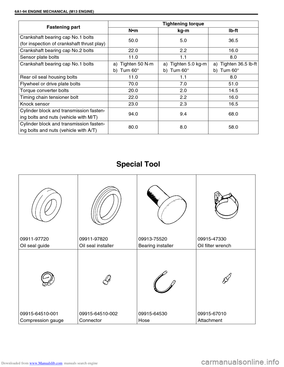
Special Tool
Crankshaft bearing cap No.1 bolts
(for inspection of crankshaft thrust play)50.0 5.0 36.5
Crankshaft bearing cap No.2 bolts 22.0 2.2 16.0
Sensor plate bolts 11.0 1.1 8.0
Crankshaft bearing cap No.1 bolts a) Tighten 50 N·m
b) Turn 60°a) Tighten 5.0 kg-m
b) Turn 60°a) Tighten 36.5 lb-ft
b) Turn 60°
Rear oil seal housing bolts 11.0 1.1 8.0
Flywheel or drive plate bolts 70.0 7.0 51.0
Torque converter bolts 20.0 2.0 14.5
Timing chain tensioner bolt 22.0 2.2 16.0
Knock sensor 23.0 2.3 16.5
Cylinder block and transmission fasten-
ing bolts and nuts (vehicle with M/T)94.0 9.4 68.0
Cylinder block and transmission fasten-
ing bolts and nuts (vehicle with A/T)80.0 8.0 58.0 Fastening partTightening torque
Nm kg-m lb-ft
09911-97720 09911-97820 09913-75520 09915-47330
Oil seal guide Oil seal installer Bearing installer Oil filter wrench
09915-64510-001 09915-64510-002 09915-64530 09915-67010
Compression gauge Connector Hose Attachment
Page 610 of 687
Downloaded from www.Manualslib.com manuals search engine ENGINE AND EMISSION CONTROL SYSTEM 6E-5
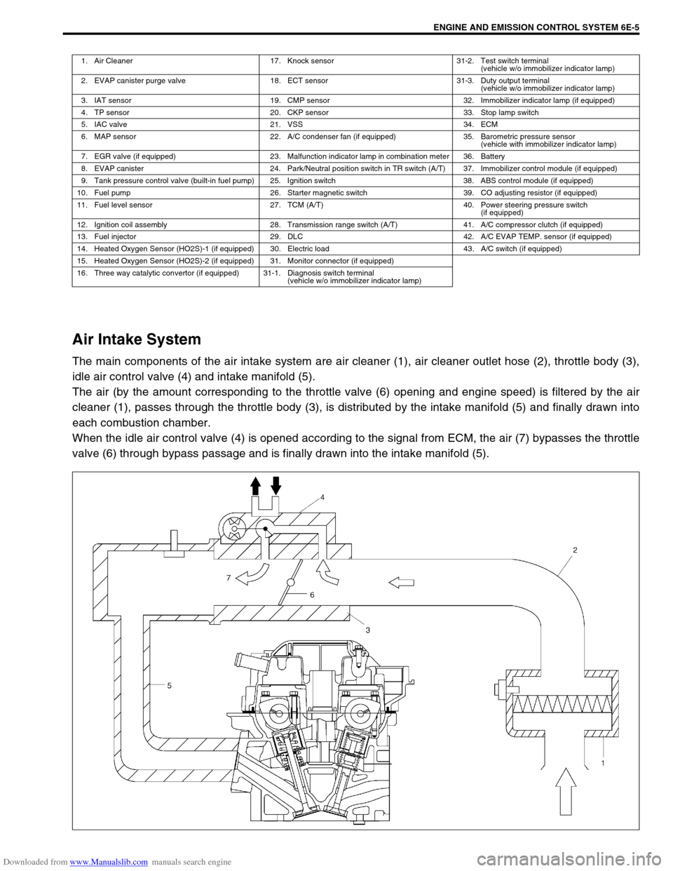
Air Intake System
The main components of the air intake system are air cleaner (1), air cleaner outlet hose (2), throttle body (3),
idle air control valve (4) and intake manifold (5).
The air (by the amount corresponding to the throttle valve (6) opening and engine speed) is filtered by the air
cleaner (1), passes through the throttle body (3), is distributed by the intake manifold (5) and finally drawn into
each combustion chamber.
When the idle air control valve (4) is opened according to the signal from ECM, the air (7) bypasses the throttle
valve (6) through bypass passage and is finally drawn into the intake manifold (5).
1. Air Cleaner 17. Knock sensor 31-2. Test switch terminal
(vehicle w/o immobilizer indicator lamp)
2. EVAP canister purge valve 18. ECT sensor 31-3. Duty output terminal
(vehicle w/o immobilizer indicator lamp)
3. IAT sensor 19. CMP sensor 32. Immobilizer indicator lamp (if equipped)
4. TP sensor 20. CKP sensor 33. Stop lamp switch
5. IAC valve 21. VSS 34. ECM
6. MAP sensor 22. A/C condenser fan (if equipped) 35. Barometric pressure sensor
(vehicle with immobilizer indicator lamp)
7. EGR valve (if equipped) 23. Malfunction indicator lamp in combination meter 36. Battery
8. EVAP canister 24. Park/Neutral position switch in TR switch (A/T) 37. Immobilizer control module (if equipped)
9. Tank pressure control valve (built-in fuel pump) 25. Ignition switch 38. ABS control module (if equipped)
10. Fuel pump 26. Starter magnetic switch 39. CO adjusting resistor (if equipped)
11. Fuel level sensor 27. TCM (A/T) 40. Power steering pressure switch
(if equipped)
12. Ignition coil assembly 28. Transmission range switch (A/T) 41. A/C compressor clutch (if equipped)
13. Fuel injector 29. DLC 42. A/C EVAP TEMP. sensor (if equipped)
14. Heated Oxygen Sensor (HO2S)-1 (if equipped) 30. Electric load 43. A/C switch (if equipped)
15. Heated Oxygen Sensor (HO2S)-2 (if equipped) 31. Monitor connector (if equipped)
16. Three way catalytic convertor (if equipped) 31-1. Diagnosis switch terminal
(vehicle w/o immobilizer indicator lamp)
Page 612 of 687
Downloaded from www.Manualslib.com manuals search engine ENGINE AND EMISSION CONTROL SYSTEM 6E-7
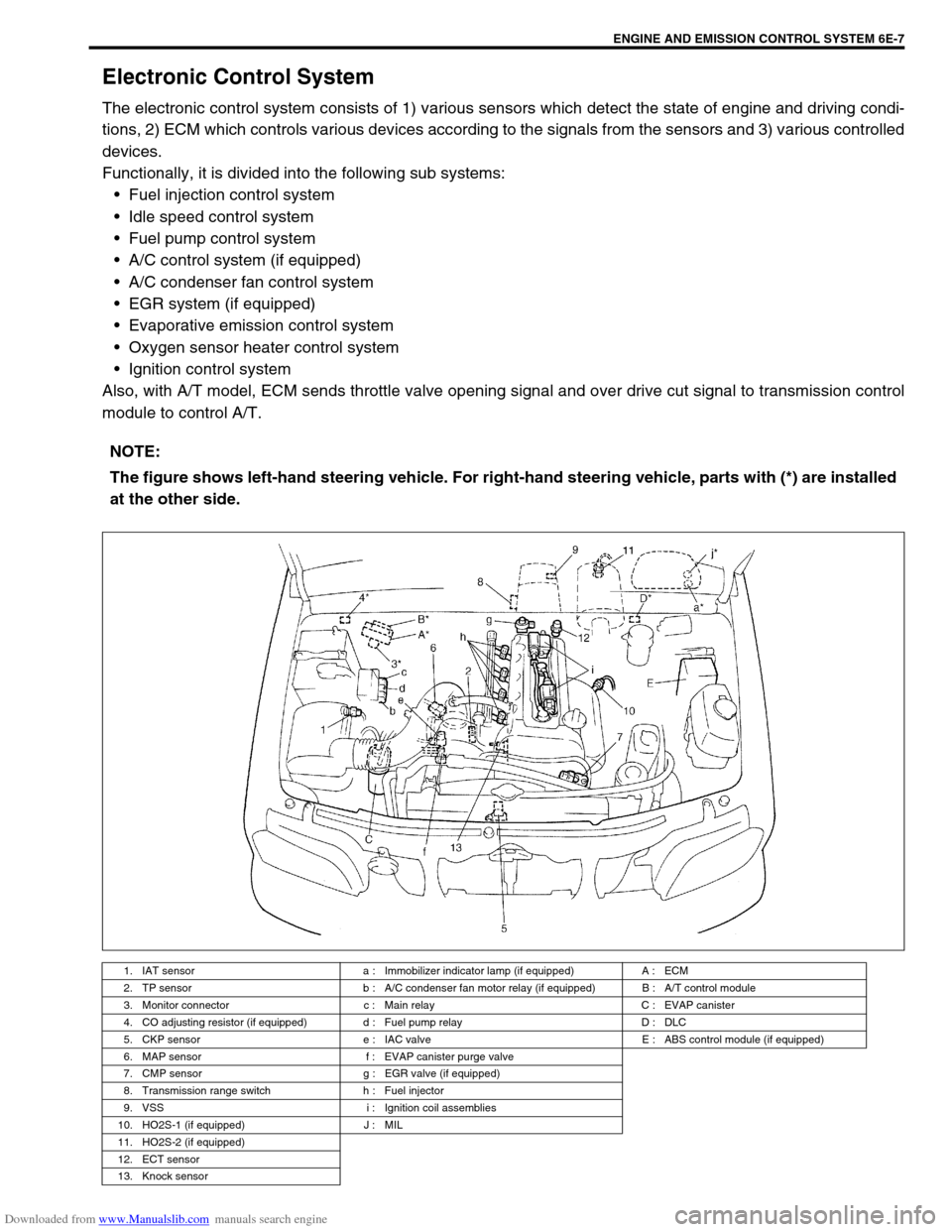
Electronic Control System
The electronic control system consists of 1) various sensors which detect the state of engine and driving condi-
tions, 2) ECM which controls various devices according to the signals from the sensors and 3) various controlled
devices.
Functionally, it is divided into the following sub systems:
Fuel injection control system
Idle speed control system
Fuel pump control system
A/C control system (if equipped)
A/C condenser fan control system
EGR system (if equipped)
Evaporative emission control system
Oxygen sensor heater control system
Ignition control system
Also, with A/T model, ECM sends throttle valve opening signal and over drive cut signal to transmission control
module to control A/T.
NOTE:
The figure shows left-hand steering vehicle. For right-hand steering vehicle, parts with (*) are installed
at the other side.
1. IAT sensor a : Immobilizer indicator lamp (if equipped) A : ECM
2. TP sensor b : A/C condenser fan motor relay (if equipped) B : A/T control module
3. Monitor connector c : Main relay C : EVAP canister
4. CO adjusting resistor (if equipped) d : Fuel pump relay D : DLC
5. CKP sensor e : IAC valve E : ABS control module (if equipped)
6. MAP sensor f : EVAP canister purge valve
7. CMP sensor g : EGR valve (if equipped)
8. Transmission range switch h : Fuel injector
9. VSS i : Ignition coil assemblies
10. HO2S-1 (if equipped) J : MIL
11. HO2S-2 (if equipped)
12. ECT sensor
13. Knock sensor