2005 SUZUKI JIMNY Connector
[x] Cancel search: ConnectorPage 640 of 687

Downloaded from www.Manualslib.com manuals search engine ENGINE AND EMISSION CONTROL SYSTEM 6E-35
Crankshaft position sensor
INSPECTION
Check crankshaft position sensor referring to step 2 and 6 of
“DTC P0335 (No.23) Flow Table” in Section 6. If malfunction is
found, replace.
REMOVAL
1) Disconnect negative cable at battery.
2) Remove generator drive belt, loosen pivot bolt and move
generator outward.
3) Disconnect connector from crankshaft position sensor.
4) Remove crankshaft position sensor (1) from cylinder block.
INSTALLATION
1) Check to make sure that crankshaft position sensor and pul-
ley tooth is free from any metal particles and damage.
2) Install crankshaft position sensor to cylinder block.
3) Connect connector to it securely.
4) Adjust generator belt tension, refer to “Water Pump Belt Ten-
sion” in Section 6B.
5) Connect negative cable to battery.
Page 644 of 687

Downloaded from www.Manualslib.com manuals search engine ENGINE AND EMISSION CONTROL SYSTEM 6E-39
REMOVAL
1) Disconnect negative cable at battery.
2) Disconnect EGR valve connector.
3) Remove EGR pipe.
4) Remove EGR valve and gasket from cylinder head.
INSPECTION
1) Check resistance between following terminals of EGR valve
(1) in each pair.
If found faulty, replace EGR valve assembly.
EGR valve resistance
2) Remove carbon from EGR valve (1) gas passage.
3) Inspect valve (2), valve seat (3) and rod for fault, cracks,
bend or other damage.
If found faulty, replace EGR valve assembly.
INSTALLATION
Reverse removal procedure noting following.
Clean mating surface of valve and cylinder head.
Use new gaskets.
Evaporative emission (EVAP) control system
EVAP CANISTER PURGE INSPECTION
Terminal Standard resistance
A – B
C – B
F – E
D – E 20 – 24
Ω
ΩΩ Ω
NOTE:
Do not use any sharp-edged tool to remove carbon.
Be careful not to damage or bend EGR valve, valve seat
and rod.
NOTE:
Before inspection, check to make sure that gear shift
lever is in neutral position (with A/T model, selector lever
in “P” range) and that parking brake lever is pulled all the
way up.
Page 648 of 687

Downloaded from www.Manualslib.com manuals search engine ENGINE AND EMISSION CONTROL SYSTEM 6E-43
Tightening Torque Specifications
09931-76030
16/14 pin DLC cable Tech 2 kit (SUZUKI scan
tool) (See NOTE “C”.)
NOTE:
“A”: This kit includes the following items.
1. Tool body & washer, 2. Body plug, 3. Body attachment-1, 4. Holder, 5. Return hose & clamp,
6. Body attachment-2 & washer, 7. Hose attachment-1, 8. Hose attachment-2
“B”: This kit includes the following items and substitutes for the Tech 2 kit.
1. Storage case, 2. Operator’s manual, 3. Tech 1A, 4. DLC cable (14/26 pin, 09931-76040),
5. Test lead / probe, 6. Power source cable, 7. DLC cable adaptor, 8. Self-test adaptor
“C”: This kit includes the following items and substitutes for the Tech 1A kit.
1. Tech 2, 2. PCMCIA card, 3. DLC cable, 4. SAE 16/19 adapter, 5. Cigarette cable,
6. DLC loopback adapter, 7. Battery power cable, 8. RS232 cable, 9. RS232 adapter,
10. RS232 loopback connector, 11. Storage case, 12. Power supply
Fastening partTightening torque
Nm kg-m lb-ft
TP sensor mounting screw 2.5 0.25 1.8
IAC valve screw 3.5 0.35 2.5
ECT sensor 15 1.5 11.5
Heated oxygen sensor-1 and -2 45 4.5 32.5
Camshaft position sensor 10 1.0 7.5
Fuel pressure regulator bolt 10 1.0 7.5
Page 651 of 687

Downloaded from www.Manualslib.com manuals search engine 6F-2 IGNITION SYSTEM (ELECTRONIC IGNITION SYSTEM)
General Description
The ignition system is an electronic (distributorless) ignition system. It consists of the parts as described below
and has an electronic ignition control system.
ECM
It detects the engine and vehicle conditions through the signals from the sensors, determines the most suit-
able ignition timing and time for electricity to flow to the primary coil and sends a signal to the ignitor (power
unit) in the ignition coil assembly.
Ignition coil assembly (including an ignitor)
The ignition coil assembly has a built-in ignitor which turns ON and OFF the current flow to the primary coil
according to the signal from ECM. When the current flow to the primary coil is turned OFF, a high voltage is
induced in the secondary coil.
High tension cords and spark plugs.
CMP sensor (Camshaft position sensor) and CKP sensor (Crankshaft position sensor)
Using signals from these sensors, ECM identifies the specific cylinder whose piston is in the compression
stroke, detects the crank angle and adjust initial ignition timing automatically.
TP sensor, ECT sensor, MAP sensor and other sensors/switches
Refer to “Electronic Control System” in Section 6E for details.
Although this ignition system does not have a distributor, it has two ignition coil assemblies (one is for No.1 and
No.4 spark plugs and the other is for No.2 and No.3 spark plugs). When an ignition signal is sent from ECM to
the ignitor in the ignition coil assembly for No.1 and No.4 spark plugs, a high voltage is induced in the secondary
coil and that passes through the high-tension cords and causes No.1 and No.4 spark plugs to spark simulta-
neously. Likewise, when an ignition signal is sent to the ignitor in the other ignition coil assembly, No.2 and No.3
spark plugs spark simultaneously.
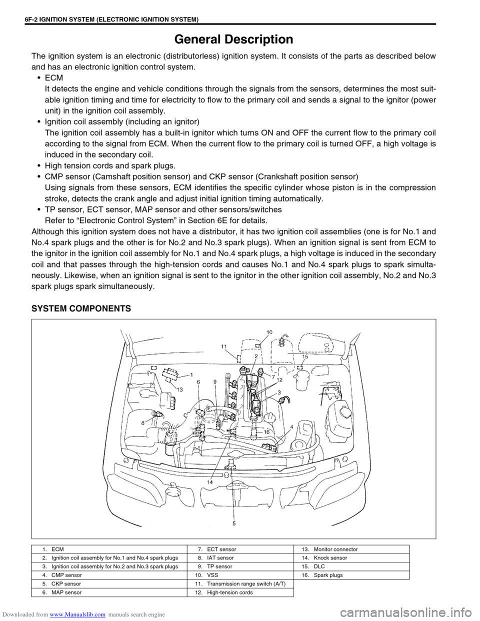
SYSTEM COMPONENTS
1. ECM 7. ECT sensor 13. Monitor connector
2. Ignition coil assembly for No.1 and No.4 spark plugs 8. IAT sensor 14. Knock sensor
3. Ignition coil assembly for No.2 and No.3 spark plugs 9. TP sensor 15. DLC
4. CMP sensor 10. VSS 16. Spark plugs
5. CKP sensor 11. Transmission range switch (A/T)
6. MAP sensor 12. High-tension cords
Page 654 of 687

Downloaded from www.Manualslib.com manuals search engine IGNITION SYSTEM (ELECTRONIC IGNITION SYSTEM 6F-5
On-Vehicle Service
Ignition Spark Test
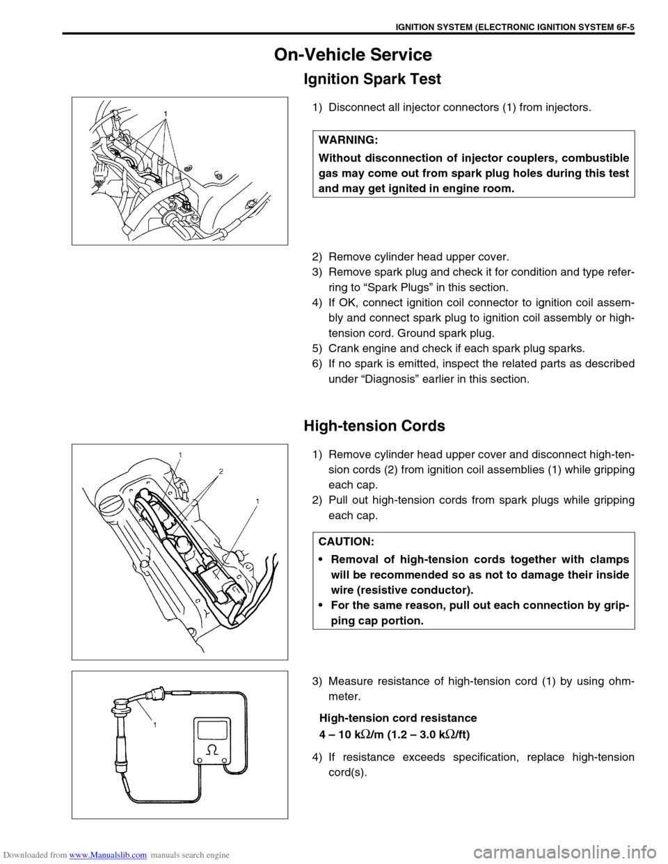
1) Disconnect all injector connectors (1) from injectors.
2) Remove cylinder head upper cover.
3) Remove spark plug and check it for condition and type refer-
ring to “Spark Plugs” in this section.
4) If OK, connect ignition coil connector to ignition coil assem-
bly and connect spark plug to ignition coil assembly or high-
tension cord. Ground spark plug.
5) Crank engine and check if each spark plug sparks.
6) If no spark is emitted, inspect the related parts as described
under “Diagnosis” earlier in this section.
High-tension Cords
1) Remove cylinder head upper cover and disconnect high-ten-
sion cords (2) from ignition coil assemblies (1) while gripping
each cap.
2) Pull out high-tension cords from spark plugs while gripping
each cap.
3) Measure resistance of high-tension cord (1) by using ohm-
meter.
High-tension cord resistance
4 – 10 k
Ω/m (1.2 – 3.0 kΩ/ft)
4) If resistance exceeds specification, replace high-tension
cord(s). WARNING:
Without disconnection of injector couplers, combustible
gas may come out from spark plug holes during this test
and may get ignited in engine room.
CAUTION:
Removal of high-tension cords together with clamps
will be recommended so as not to damage their inside
wire (resistive conductor).
For the same reason, pull out each connection by grip-
ping cap portion.
Page 656 of 687

Downloaded from www.Manualslib.com manuals search engine IGNITION SYSTEM (ELECTRONIC IGNITION SYSTEM 6F-7
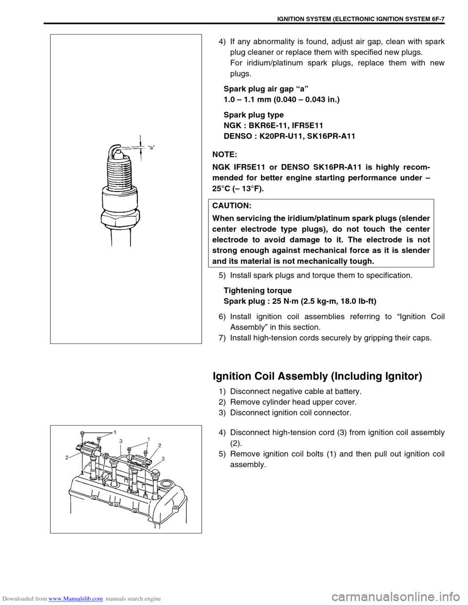
4) If any abnormality is found, adjust air gap, clean with spark
plug cleaner or replace them with specified new plugs.
For iridium/platinum spark plugs, replace them with new
plugs.
Spark plug air gap “a”
1.0 – 1.1 mm (0.040 – 0.043 in.)
Spark plug type
NGK : BKR6E-11, IFR5E11
DENSO : K20PR-U11, SK16PR-A11
5) Install spark plugs and torque them to specification.
Tightening torque
Spark plug : 25 N·m (2.5 kg-m, 18.0 lb-ft)
6) Install ignition coil assemblies referring to “Ignition Coil
Assembly” in this section.
7) Install high-tension cords securely by gripping their caps.
Ignition Coil Assembly (Including Ignitor)
1) Disconnect negative cable at battery.
2) Remove cylinder head upper cover.
3) Disconnect ignition coil connector.
4) Disconnect high-tension cord (3) from ignition coil assembly
(2).
5) Remove ignition coil bolts (1) and then pull out ignition coil
assembly. NOTE:
NGK IFR5E11 or DENSO SK16PR-A11 is highly recom-
mended for better engine starting performance under –
25°C (– 13°F).
CAUTION:
When servicing the iridium/platinum spark plugs (slender
center electrode type plugs), do not touch the center
electrode to avoid damage to it. The electrode is not
strong enough against mechanical force as it is slender
and its material is not mechanically tough.
Page 658 of 687

Downloaded from www.Manualslib.com manuals search engine IGNITION SYSTEM (ELECTRONIC IGNITION SYSTEM 6F-9
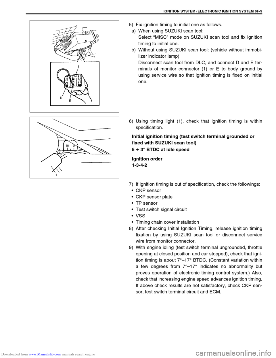
5) Fix ignition timing to initial one as follows.
a) When using SUZUKI scan tool:
Select “MISC” mode on SUZUKI scan tool and fix ignition
timing to initial one.
b) Without using SUZUKI scan tool: (vehicle without immobi-
lizer indicator lamp)
Disconnect scan tool from DLC, and connect D and E ter-
minals of monitor connector (1) or E to body ground by
using service wire so that ignition timing is fixed on initial
one.
6) Using timing light (1), check that ignition timing is within
specification.
Initial ignition timing (test switch terminal grounded or
fixed with SUZUKI scan tool)
5
± 3° BTDC at idle speed
Ignition order
1-3-4-2
7) If ignition timing is out of specification, check the followings:
CKP sensor
CKP sensor plate
TP sensor
Test switch signal circuit
VSS
Timing chain cover installation
8) After checking Initial Ignition Timing, release ignition timing
fixation by using SUZUKI scan tool or disconnect service
wire from monitor connector.
9) With engine idling (test switch terminal ungrounded, throttle
opening at closed position and car stopped), check that igni-
tion timing is about 7°–17° BTDC. (Constant variation within
a few degrees from 7°–17° indicates no abnormality but
proves operation of electronic timing control system.) Also,
check that increasing engine speed advances ignition timing.
If above check results are not satisfactory, check CKP sen-
sor, test switch terminal circuit and ECM.
Page 659 of 687

Downloaded from www.Manualslib.com manuals search engine 6F-10 IGNITION SYSTEM (ELECTRONIC IGNITION SYSTEM)
Special Tools
Tightening Torque Specification
09931-76011 09931-76030
Tech 1A kit (SUZUKI scan
tool) (See NOTE “A”.)Mass storage cartridge for
Tech 1A16/14 pin DLC adapter for
Tech 1ATech 2 kit (SUZUKI scan
tool) (See NOTE “B”. )
NOTE:
“A” : This kit includes the following items and substitutes for the Tech 2 kit.
1. Storage case, 2. Operator’s manual, 3. Tech 1A, 4. DLC cable (14/26 pin, 09931-76040),
5. Test lead/probe, 6. Power source cable, 7. DLC cable adaptor, 8. Self-test adaptor
“B” : This kit includes the following items and substitutes for the Tech 1A kit.
1. Tech 2, 2. PCMCIA card, 3. DLC cable, 4. SAE 16/19 adapter, 5. Cigarette cable,
6. DLC loopback adapter, 7. Battery power cable, 8. RS232 cable, 9. RS232 adapter,
10. RS232 loopback connector, 11. Storage case, 12. Power supply
Fastening partTightening torque
Nm kg-m lb-ft
Spark plug 25 2.5 18.0