Page 488 of 687
Downloaded from www.Manualslib.com manuals search engine ENGINE MECHANICAL (M13 ENGINE) 6A1-7
Oil Pressure Check
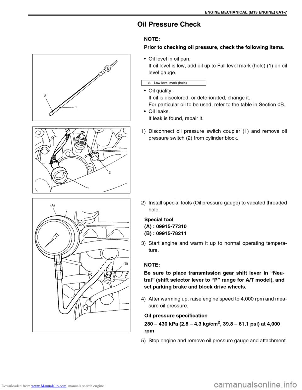
Oil level in oil pan.
If oil level is low, add oil up to Full level mark (hole) (1) on oil
level gauge.
Oil quality.
If oil is discolored, or deteriorated, change it.
For particular oil to be used, refer to the table in Section 0B.
Oil leaks.
If leak is found, repair it.
1) Disconnect oil pressure switch coupler (1) and remove oil
pressure switch (2) from cylinder block.
2) Install special tools (Oil pressure gauge) to vacated threaded
hole.
Special tool
(A) : 09915-77310
(B) : 09915-78211
3) Start engine and warm it up to normal operating tempera-
ture.
4) After warming up, raise engine speed to 4,000 rpm and mea-
sure oil pressure.
Oil pressure specification
280 – 430 kPa (2.8 – 4.3 kg/cm
2, 39.8 – 61.1 psi) at 4,000
rpm
5) Stop engine and remove oil pressure gauge and attachment.NOTE:
Prior to checking oil pressure, check the following items.
2. Low level mark (hole)
NOTE:
Be sure to place transmission gear shift lever in “Neu-
tral” (shift selector lever to “P” range for A/T model), and
set parking brake and block drive wheels.
Page 513 of 687
Downloaded from www.Manualslib.com manuals search engine 6A1-32 ENGINE MECHANICAL (M13 ENGINE)
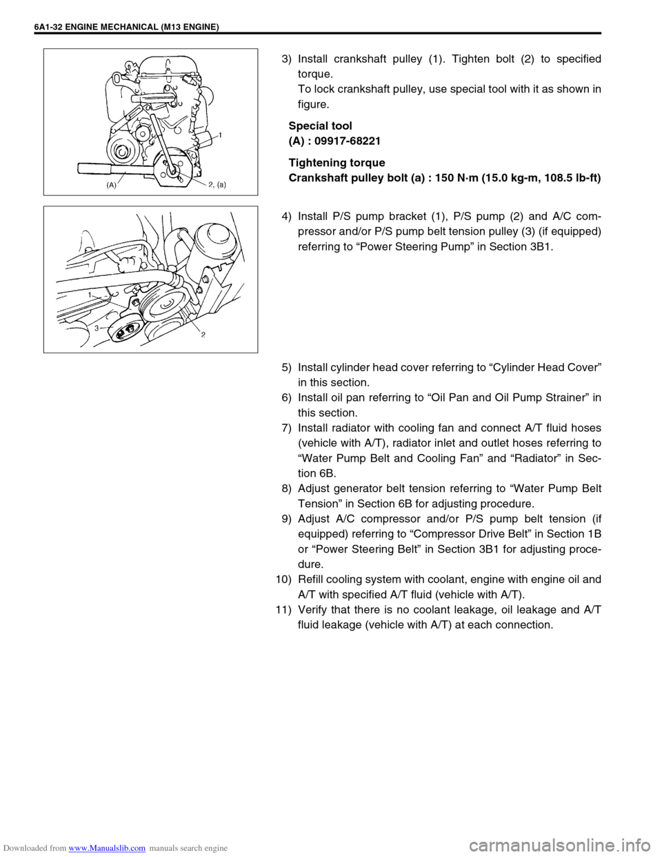
3) Install crankshaft pulley (1). Tighten bolt (2) to specified
torque.
To lock crankshaft pulley, use special tool with it as shown in
figure.
Special tool
(A) : 09917-68221
Tightening torque
Crankshaft pulley bolt (a) : 150 N·m (15.0 kg-m, 108.5 lb-ft)
4) Install P/S pump bracket (1), P/S pump (2) and A/C com-
pressor and/or P/S pump belt tension pulley (3) (if equipped)
referring to “Power Steering Pump” in Section 3B1.
5) Install cylinder head cover referring to “Cylinder Head Cover”
in this section.
6) Install oil pan referring to “Oil Pan and Oil Pump Strainer” in
this section.
7) Install radiator with cooling fan and connect A/T fluid hoses
(vehicle with A/T), radiator inlet and outlet hoses referring to
“Water Pump Belt and Cooling Fan” and “Radiator” in Sec-
tion 6B.
8) Adjust generator belt tension referring to “Water Pump Belt
Tension” in Section 6B for adjusting procedure.
9) Adjust A/C compressor and/or P/S pump belt tension (if
equipped) referring to “Compressor Drive Belt” in Section 1B
or “Power Steering Belt” in Section 3B1 for adjusting proce-
dure.
10) Refill cooling system with coolant, engine with engine oil and
A/T with specified A/T fluid (vehicle with A/T).
11) Verify that there is no coolant leakage, oil leakage and A/T
fluid leakage (vehicle with A/T) at each connection.
Page 528 of 687

Downloaded from www.Manualslib.com manuals search engine ENGINE MECHANICAL (M13 ENGINE) 6A1-47
5) After applying engine oil to housing bolts, tighten them tem-
porarily first. Then tighten them by the following numerical
order in figure. Tighten a little at a time and evenly among
bolts and repeat tightening sequence two or three times
before they are tightened to specified torque.
Tightening torque
Camshaft housing bolts (a) : 11 N·m (1.1 kg-m, 8.0 lb-ft)
6) Install timing chain with crankshaft sprocket referring to
“Timing Chain and Chain Tensioner” in this section.
7) Install timing chain cover referring to “Timing Chain Cover” in
this section.
8) Check valve lashes referring to “Valve Lash” in this section.
9) Install cylinder head cover and oil pan referring to “Cylinder
Head Cover” and “Oil Pan and Oil Pump Strainer” in this sec-
tion.
10) Install radiator with cooling fan and connect A/T fluid hoses
(vehicle with A/T), radiator inlet and outlet hoses referring to
“Water Pump Belt and Cooling Fan” and “Radiator” in Sec-
tion 6B.
11) Adjust generator belt tension referring to “Water Pump Belt
Tension” in Section 6B.
12) Adjust A/C compressor and/or P/S pump belt tension (if
equipped) referring to “Compressor Drive Belt” in Section 1B
or “Power Steering Belt” in Section 3B1.
13) Refill cooling system with coolant, engine with engine oil and
A/T with specified A/T fluid (vehicle with A/T).
14) Verify that there is no coolant leakage, oil leakage and A/T
fluid leakage (vehicle with A/T) at each connection.
Page 533 of 687
Downloaded from www.Manualslib.com manuals search engine 6A1-52 ENGINE MECHANICAL (M13 ENGINE)
DISASSEMBLY
1) For ease in servicing cylinder head, remove intake manifold,
injectors and exhaust manifold from cylinder head.
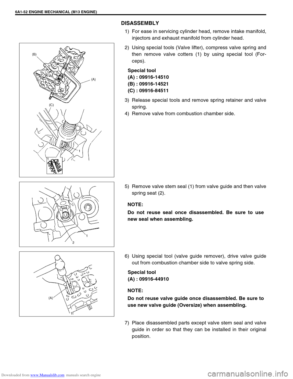
2) Using special tools (Valve lifter), compress valve spring and
then remove valve cotters (1) by using special tool (For-
ceps).
Special tool
(A) : 09916-14510
(B) : 09916-14521
(C) : 09916-84511
3) Release special tools and remove spring retainer and valve
spring.
4) Remove valve from combustion chamber side.
5) Remove valve stem seal (1) from valve guide and then valve
spring seat (2).
6) Using special tool (valve guide remover), drive valve guide
out from combustion chamber side to valve spring side.
Special tool
(A) : 09916-44910
7) Place disassembled parts except valve stem seal and valve
guide in order so that they can be installed in their original
position.
NOTE:
Do not reuse seal once disassembled. Be sure to use
new seal when assembling.
NOTE:
Do not reuse valve guide once disassembled. Be sure to
use new valve guide (Oversize) when assembling.
Page 539 of 687
Downloaded from www.Manualslib.com manuals search engine 6A1-58 ENGINE MECHANICAL (M13 ENGINE)
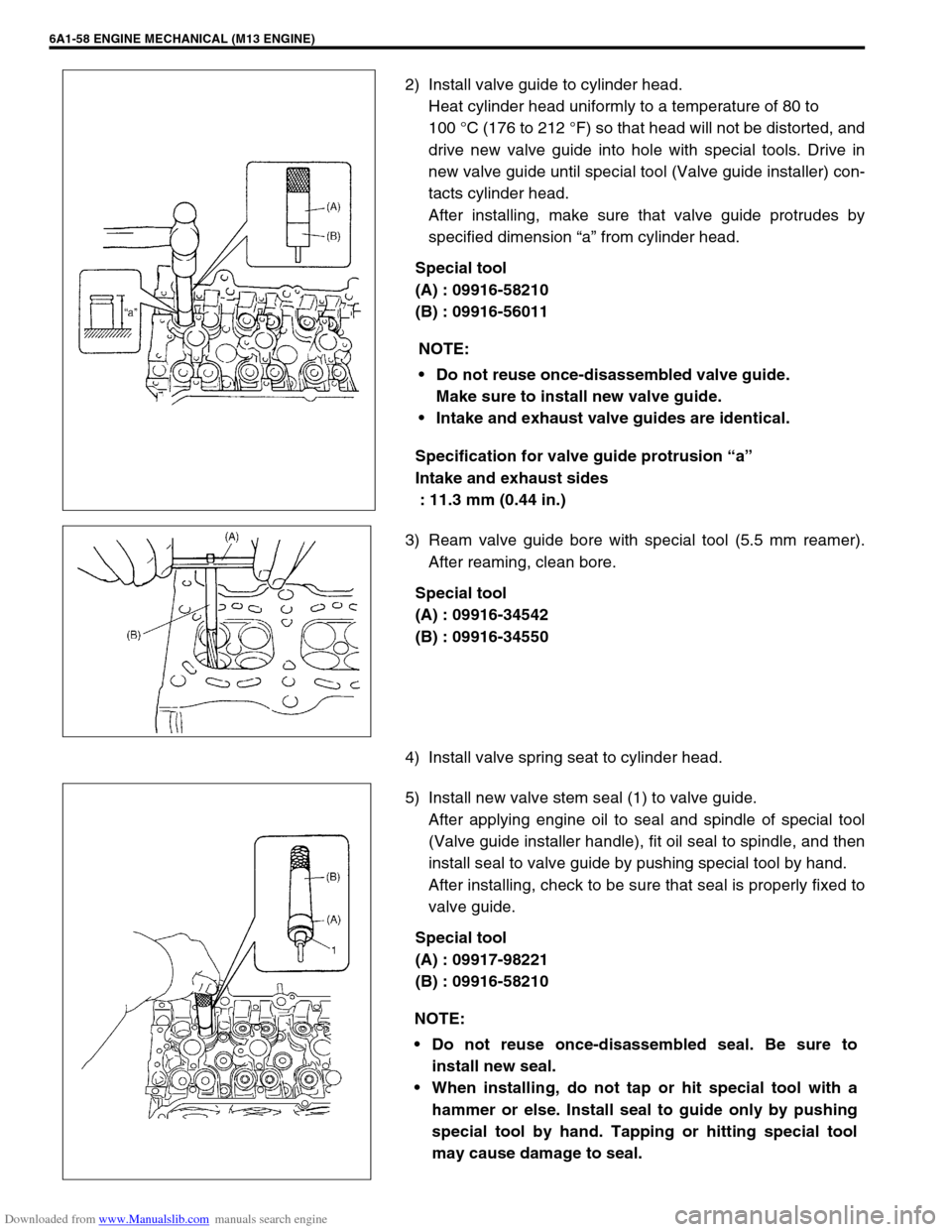
2) Install valve guide to cylinder head.
Heat cylinder head uniformly to a temperature of 80 to
100 °C (176 to 212 °F) so that head will not be distorted, and
drive new valve guide into hole with special tools. Drive in
new valve guide until special tool (Valve guide installer) con-
tacts cylinder head.
After installing, make sure that valve guide protrudes by
specified dimension “a” from cylinder head.
Special tool
(A) : 09916-58210
(B) : 09916-56011
Specification for valve guide protrusion “a”
Intake and exhaust sides
: 11.3 mm (0.44 in.)
3) Ream valve guide bore with special tool (5.5 mm reamer).
After reaming, clean bore.
Special tool
(A) : 09916-34542
(B) : 09916-34550
4) Install valve spring seat to cylinder head.
5) Install new valve stem seal (1) to valve guide.
After applying engine oil to seal and spindle of special tool
(Valve guide installer handle), fit oil seal to spindle, and then
install seal to valve guide by pushing special tool by hand.
After installing, check to be sure that seal is properly fixed to
valve guide.
Special tool
(A) : 09917-98221
(B) : 09916-58210NOTE:
Do not reuse once-disassembled valve guide.
Make sure to install new valve guide.
Intake and exhaust valve guides are identical.
NOTE:
Do not reuse once-disassembled seal. Be sure to
install new seal.
When installing, do not tap or hit special tool with a
hammer or else. Install seal to guide only by pushing
special tool by hand. Tapping or hitting special tool
may cause damage to seal.
Page 542 of 687

Downloaded from www.Manualslib.com manuals search engine ENGINE MECHANICAL (M13 ENGINE) 6A1-61
6) Install exhaust manifold stiffener and exhaust pipe referring
to “Exhaust Manifold” in this section.
7) Install camshafts, timing chain and chain cover referring to
“Camshaft, Tappet and Shim”, “Timing Chain and Chain
Tensioner” and “Timing Chain Cover” in this section.
8) Install cylinder head cover and oil pan referring to “Cylinder
Head Cover” and “Oil Pan and Oil Pump Strainer” in this sec-
tion.
9) Install intake manifold stiffener and connect each hoses and
electric lead wires securely.
10) Install air cleaner outlet hoses.
11) Install radiator with cooling fan and connect A/T fluid hoses
(vehicle with A/T), radiator inlet and outlet hoses referring to
“Water Pump Belt and Cooling Fan” and “Radiator” in Sec-
tion 6B.
12) Adjust generator belt tension referring to “Water Pump Belt
Tension” in Section 6B.
13) Adjust A/C compressor and/or P/S pump belt tension (if
equipped) referring to “Compressor Drive Belt” in Section 1B
or “Power Steering Belt” in Section 3B1.
14) Adjust accelerator cable play referring to “Accelerator Cable
Adjustment” in Section 6E.
15) Check to ensure that all removed parts are back in place.
Reinstall any necessary parts which have not been rein-
stalled.
16) Refill cooling system with coolant, engine with engine oil and
A/T with specified A/T fluid (vehicle with A/T).
17) Connect negative cable at battery.
18) Verify that there is no fuel leakage, coolant leakage, oil leak-
age, A/T fluid leakage (vehicle with A/T) and exhaust gas
leakage at each connection.
Page 552 of 687
Downloaded from www.Manualslib.com manuals search engine ENGINE MECHANICAL (M13 ENGINE) 6A1-71
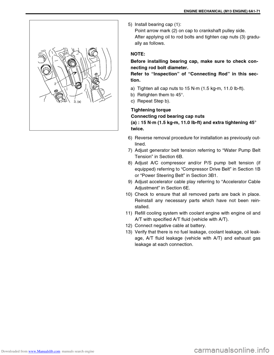
5) Install bearing cap (1):
Point arrow mark (2) on cap to crankshaft pulley side.
After applying oil to rod bolts and tighten cap nuts (3) gradu-
ally as follows.
a) Tighten all cap nuts to 15 N·m (1.5 kg-m, 11.0 lb-ft).
b) Retighten them to 45°.
c) Repeat Step b).
Tightening torque
Connecting rod bearing cap nuts
(a) : 15 N·m (1.5 kg-m, 11.0 lb-ft) and extra tightening 45°
twice.
6) Reverse removal procedure for installation as previously out-
lined.
7) Adjust generator belt tension referring to “Water Pump Belt
Tension” in Section 6B.
8) Adjust A/C compressor and/or P/S pump belt tension (if
equipped) referring to “Compressor Drive Belt” in Section 1B
or “Power Steering Belt” in Section 3B1.
9) Adjust accelerator cable play referring to “Accelerator Cable
Adjustment” in Section 6E.
10) Check to ensure that all removed parts are back in place.
Reinstall any necessary parts which have not been rein-
stalled.
11) Refill cooling system with coolant engine with engine oil and
A/T with specified A/T fluid (vehicle with A/T).
12) Connect negative cable at battery.
13) Verify that there is no fuel leakage, coolant leakage, oil leak-
age, A/T fluid leakage (vehicle with A/T) and exhaust gas
leakage at each connection. NOTE:
Before installing bearing cap, make sure to check con-
necting rod bolt diameter.
Refer to “Inspection” of “Connecting Rod” in this sec-
tion.
Page 556 of 687
Downloaded from www.Manualslib.com manuals search engine ENGINE MECHANICAL (M13 ENGINE) 6A1-75
18) Remove heated oxygen sensor bracket from cylinder head
and detach No.1 heated oxygen sensor coupler from its
bracket.
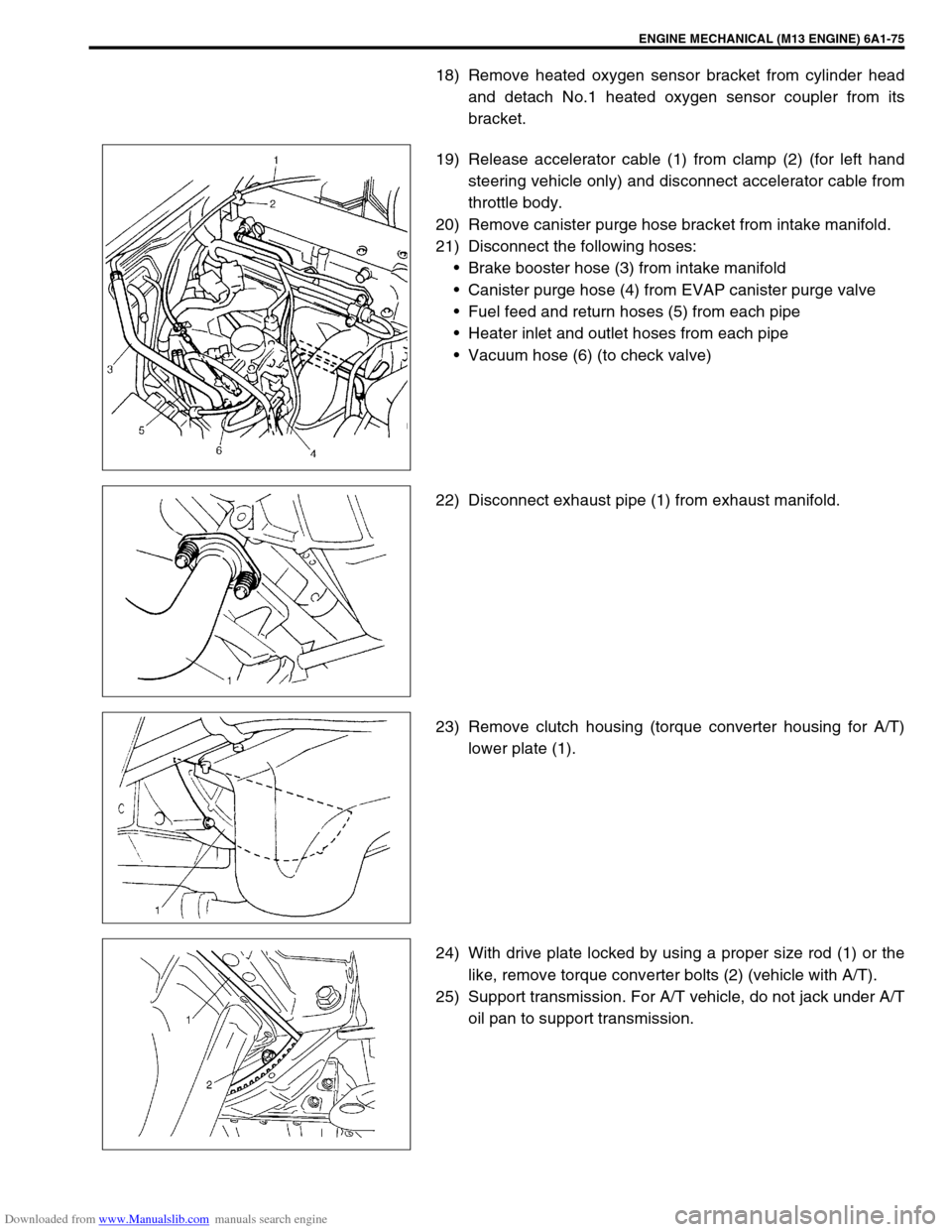
19) Release accelerator cable (1) from clamp (2) (for left hand
steering vehicle only) and disconnect accelerator cable from
throttle body.
20) Remove canister purge hose bracket from intake manifold.
21) Disconnect the following hoses:
Brake booster hose (3) from intake manifold
Canister purge hose (4) from EVAP canister purge valve
Fuel feed and return hoses (5) from each pipe
Heater inlet and outlet hoses from each pipe
Vacuum hose (6) (to check valve)
22) Disconnect exhaust pipe (1) from exhaust manifold.
23) Remove clutch housing (torque converter housing for A/T)
lower plate (1).
24) With drive plate locked by using a proper size rod (1) or the
like, remove torque converter bolts (2) (vehicle with A/T).
25) Support transmission. For A/T vehicle, do not jack under A/T
oil pan to support transmission.