2005 SUZUKI JIMNY drive
[x] Cancel search: drivePage 612 of 687

Downloaded from www.Manualslib.com manuals search engine ENGINE AND EMISSION CONTROL SYSTEM 6E-7
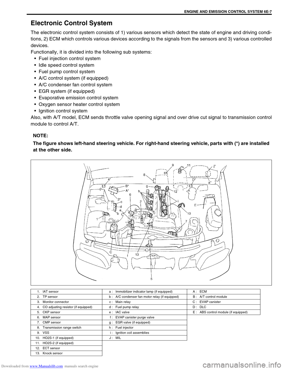
Electronic Control System
The electronic control system consists of 1) various sensors which detect the state of engine and driving condi-
tions, 2) ECM which controls various devices according to the signals from the sensors and 3) various controlled
devices.
Functionally, it is divided into the following sub systems:
Fuel injection control system
Idle speed control system
Fuel pump control system
A/C control system (if equipped)
A/C condenser fan control system
EGR system (if equipped)
Evaporative emission control system
Oxygen sensor heater control system
Ignition control system
Also, with A/T model, ECM sends throttle valve opening signal and over drive cut signal to transmission control
module to control A/T.
NOTE:
The figure shows left-hand steering vehicle. For right-hand steering vehicle, parts with (*) are installed
at the other side.
1. IAT sensor a : Immobilizer indicator lamp (if equipped) A : ECM
2. TP sensor b : A/C condenser fan motor relay (if equipped) B : A/T control module
3. Monitor connector c : Main relay C : EVAP canister
4. CO adjusting resistor (if equipped) d : Fuel pump relay D : DLC
5. CKP sensor e : IAC valve E : ABS control module (if equipped)
6. MAP sensor f : EVAP canister purge valve
7. CMP sensor g : EGR valve (if equipped)
8. Transmission range switch h : Fuel injector
9. VSS i : Ignition coil assemblies
10. HO2S-1 (if equipped) J : MIL
11. HO2S-2 (if equipped)
12. ECT sensor
13. Knock sensor
Page 618 of 687

Downloaded from www.Manualslib.com manuals search engine ENGINE AND EMISSION CONTROL SYSTEM 6E-13
ECM TERMINAL ARRANGEMENT TABLE
For TYPE A (See NOTE)
CONNEC-
TORTERMINAL WIRE COLOR CIRCUITCONNEC-
TORTERMINAL WIRE COLOR CIRCUIT
E191 B Ground for ECM
E187 W Backup power source
2 B/R Ground for drive circuit
8R/GImmobilizer indicator lamp
(if equipped)
3 B/R Ground for drive circuitDuty output terminal (vehicle without
immobilizer indicator lamp)
4 Bl/G Canister purge valve 9––
5 Bl/OrPower steering pressure switch
(if equipped)10 Bl Main relay
6 G/Y IAC valve 11 Br Tachometer
7 P/B Heater of HO2S-1 (if equipped) 12 Y/B Data link connector (5 V)
8 W/B No.4 fuel injector 13 WHeated oxygen sensor-2
(if equipped)
9 R/W No.1 fuel injector 14 W/BIDiagnosis switch terminal
(vehicle without immobilizer indicator
lamp)
10 B/Bl Ground for sensor circuit 15 PTest switch terminal
(vehicle without immobilizer indicator
lamp)
11 W CMP sensor 16 G/W A/C SW signal (if equipped)
12––17 R/Y Lighting switch
13R
R/BlHeated oxygen sensor-1
(if equipped)
CO adjusting resistor (w/o HO2S)18 P/B A/C condenser fan relay (if equipped)
14 G/B ECT sensor 19 W/G Fuel pump relay
15 Lg/B IAT sensor 20 B/Bl Ground for sensor
16 Lg TP sensor 21 B/RThrottle opening signal output for A/T
(A/T)
17 Gr/BIEGR valve (stepper motor coil 3, if
equipped)22 Y/RFuel level gauge (vehicle with immo-
bilizer indicator lamp)
18 GrEGR valve (stepper motor coil 1, if
equipped)23––
19 Br/BIG coil assembly for No.2 and 3 spark
plugs24 Bl/Y Heater blower switch
20 Br/WIG coil assembly for No.1 and 4 spark
plugs
21 R/G No.2 fuel injector
E171––
22 Lg/R Power supply for sensor 2 R R-range signal (A/T)
23 G/R CKP sensor 3––
24––4––
25 W Knock sensor 5 B/Or Overdrive cut signal (A/T)
26 G MAP sensor 6 G/Y D-range idle-up signal (A/T)
27 W/R A/C evaporator temp. sensor 7 G/W Stop lamp switch
28 Gr/BEGR valve (stepper motor coil 4, if
equipped)8––
29 Gr/REGR valve (stepper motor coil 2, if
equipped)9 B/W Ignition switch
30––10––
31 W/G No.3 fuel injector 11 Y Vehicle speed sensor
12 G ABS signal (if equipped)
E181 P A/C compressor clutch (if equipped) 13B/Y (M/T)
B/R (A/T)Engine start signal
2 V/Y Malfunction indicator lamp 14––
3 P/G Data link connector (12 V) 15––
4 R/BI Heater of HO2S-2 (if equipped) 16 R/W Rear defogger switch (if equipped)
5 Bl/B Power source 17 G/RA/T failure signal (A/T) (vehicle with
immobilizer indicator lamp)
6 Bl/B Power source
NOTE:
See NOTE in “ECM INPUT / OUTPUT CIRCUIT DIAGRAM” for applicable model.
Page 619 of 687

Downloaded from www.Manualslib.com manuals search engine 6E-14 ENGINE AND EMISSION CONTROL SYSTEM
For TYPE B (See NOTE)
CONNEC-
TORTERMINAL WIRE COLOR CIRCUITCONNEC-
TORTERMINAL WIRE COLOR CIRCUIT
E191 B Ground for ECM
E187 W Backup power source
2 B/R Ground for drive circuit
8R/GImmobilizer indicator lamp
(if equipped)
3 B/R Ground for drive circuitDuty output terminal (vehicle without
immobilizer indicator lamp)
4 Bl/G Canister purge valve 9––
5 Bl/OrPower steering pressure switch
(if equipped)10 Bl Main relay
6 G/Y IAC valve 11 B/W Ignition switch
7 P/B Heater of HO2S-1 (if equipped) 12 R/W Rear defogger switch
8 W/B No.4 fuel injector 13––
9 R/W No.1 fuel injector 14 W/BIDiagnosis switch terminal
(vehicle without immobilizer indicator
lamp)
10 B/Bl Ground for sensor circuit 15 PTest switch terminal
(vehicle without immobilizer indicator
lamp)
11 W CMP sensor 16 G/W A/C SW signal (if equipped)
12––17 R/Y Lighting switch
13R
R/BlHeated oxygen sensor-1
(if equipped)
CO adjusting resistor (w/o HO2S)18 P/B A/C condenser fan relay (if equipped)
14 G/B ECT sensor 19 W/G Fuel pump relay
15 Lg/B IAT sensor 20B/Y (M/T)
B/R (A/T)Engine start signal
16 Lg TP sensor 21 G/W Stop lamp switch
17 Gr/BIEGR valve (stepper motor coil 3, if
equipped)22 Y Vehicle speed sensor
18 GrEGR valve (stepper motor coil 1, if
equipped)23––
19 Br/BIG coil assembly for No.2 and 3 spark
plugs24––
20 Br/WIG coil assembly for No.1 and 4 spark
plugs
21 R/G No.2 fuel injector
E171 W/R A/C evaporator temp. sensor
22 Lg/R Power supply for sensor 2 R R-range signal (A/T)
23 G/R CKP sensor 3––
24––4––
25 W Knock sensor 5 B/Or Overdrive cut signal (A/T)
26 G MAP sensor 6 G/Y D-range idle-up signal (A/T)
27––7 Y/B Data link connector
28 Gr/BEGR valve (stepper motor coil 4, if
equipped)8––
29 Gr/REGR valve (stepper motor coil 2, if
equipped)9 V/Y Malfunction indicator lamp
30––10––
31 W/G No.3 fuel injector 11 P/G Data link connector (12 V)
12 G ABS signal (if equipped)
E181 P A/C compressor clutch (if equipped) 13 Bl/Y Heater blower switch
2––14 B/Bl Ground for sensor
3––15 B/R Throttle opening sensor
4 R/BI Heater of HO2S-2 (if equipped) 16 Br Tachometer
5 Bl/B Power source 17––
6 Bl/B Power source
NOTE:
See NOTE in “ECM INPUT / OUTPUT CIRCUIT DIAGRAM” for applicable model.
Page 620 of 687

Downloaded from www.Manualslib.com manuals search engine ENGINE AND EMISSION CONTROL SYSTEM 6E-15
On-Vehicle Service
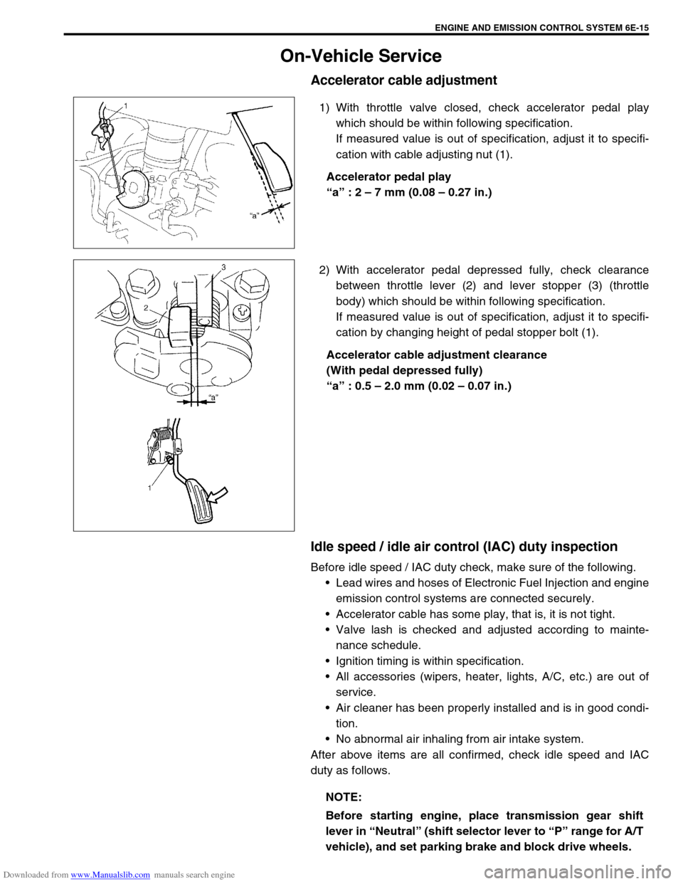
Accelerator cable adjustment
1) With throttle valve closed, check accelerator pedal play
which should be within following specification.
If measured value is out of specification, adjust it to specifi-
cation with cable adjusting nut (1).
Accelerator pedal play
“a” : 2 – 7 mm (0.08 – 0.27 in.)
2) With accelerator pedal depressed fully, check clearance
between throttle lever (2) and lever stopper (3) (throttle
body) which should be within following specification.
If measured value is out of specification, adjust it to specifi-
cation by changing height of pedal stopper bolt (1).
Accelerator cable adjustment clearance
(With pedal depressed fully)
“a” : 0.5 – 2.0 mm (0.02 – 0.07 in.)
Idle speed / idle air control (IAC) duty inspection
Before idle speed / IAC duty check, make sure of the following.
Lead wires and hoses of Electronic Fuel Injection and engine
emission control systems are connected securely.
Accelerator cable has some play, that is, it is not tight.
Valve lash is checked and adjusted according to mainte-
nance schedule.
Ignition timing is within specification.
All accessories (wipers, heater, lights, A/C, etc.) are out of
service.
Air cleaner has been properly installed and is in good condi-
tion.
No abnormal air inhaling from air intake system.
After above items are all confirmed, check idle speed and IAC
duty as follows.
NOTE:
Before starting engine, place transmission gear shift
lever in “Neutral” (shift selector lever to “P” range for A/T
vehicle), and set parking brake and block drive wheels.
Page 622 of 687

Downloaded from www.Manualslib.com manuals search engine ENGINE AND EMISSION CONTROL SYSTEM 6E-17
Idle mixture inspection / adjustment (vehicle without
heated oxygen sensor)
All vehicles not equipped with heated oxygen sensor are shipped
with their CO % factory adjusted as follows.
Engine idle mixture (CO %)
0.5 – 1.5 % at specified idle speed
Idle mixture adjustment should never be changed from the origi-
nal factory setting. However, if during diagnosis, the check indi-
cates idle mixture to be the cause of a driver performance
complaint or emission failure, the idle mixture can be adjusted
using the following procedures.
1) Check idle speed according to “Idle Speed / Idle Air Control
(IAC) Duty Inspection” in this section.
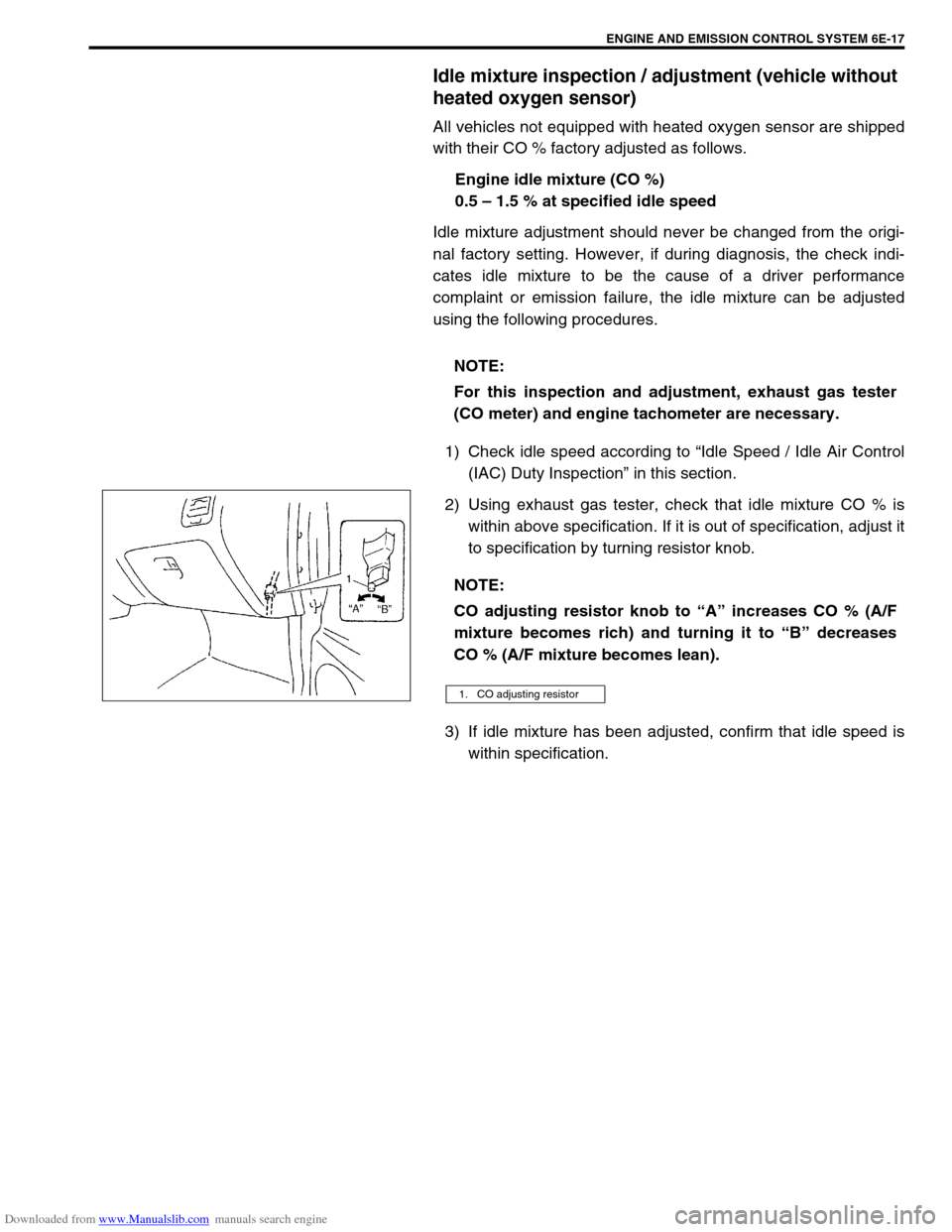
2) Using exhaust gas tester, check that idle mixture CO % is
within above specification. If it is out of specification, adjust it
to specification by turning resistor knob.
3) If idle mixture has been adjusted, confirm that idle speed is
within specification. NOTE:
For this inspection and adjustment, exhaust gas tester
(CO meter) and engine tachometer are necessary.
NOTE:
CO adjusting resistor knob to “A” increases CO % (A/F
mixture becomes rich) and turning it to “B” decreases
CO % (A/F mixture becomes lean).
1. CO adjusting resistor
Page 640 of 687

Downloaded from www.Manualslib.com manuals search engine ENGINE AND EMISSION CONTROL SYSTEM 6E-35
Crankshaft position sensor
INSPECTION
Check crankshaft position sensor referring to step 2 and 6 of
“DTC P0335 (No.23) Flow Table” in Section 6. If malfunction is
found, replace.
REMOVAL
1) Disconnect negative cable at battery.
2) Remove generator drive belt, loosen pivot bolt and move
generator outward.
3) Disconnect connector from crankshaft position sensor.
4) Remove crankshaft position sensor (1) from cylinder block.
INSTALLATION
1) Check to make sure that crankshaft position sensor and pul-
ley tooth is free from any metal particles and damage.
2) Install crankshaft position sensor to cylinder block.
3) Connect connector to it securely.
4) Adjust generator belt tension, refer to “Water Pump Belt Ten-
sion” in Section 6B.
5) Connect negative cable to battery.
Page 661 of 687

Downloaded from www.Manualslib.com manuals search engine 6G-2 CRANKING SYSTEM
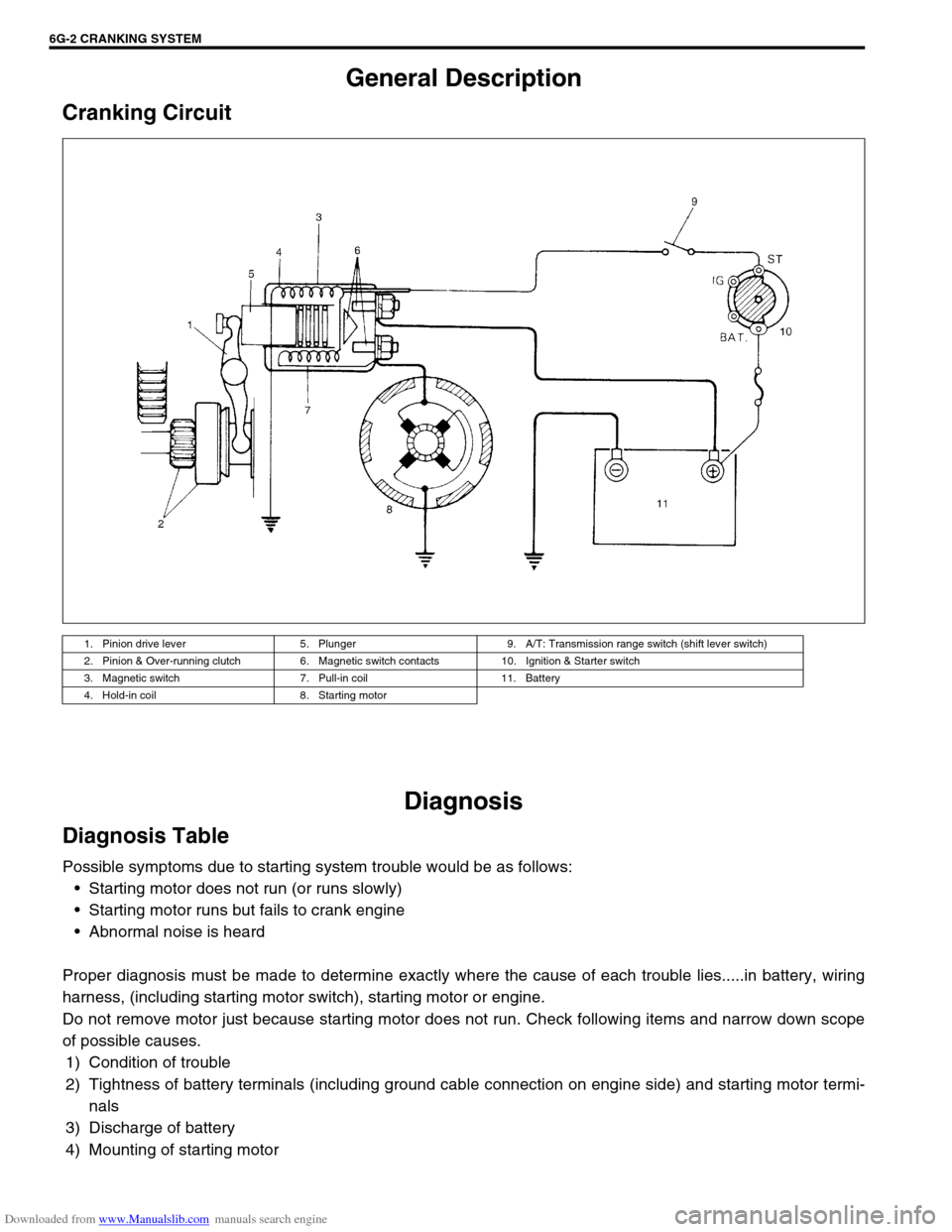
General Description
Cranking Circuit
Diagnosis
Diagnosis Table
Possible symptoms due to starting system trouble would be as follows:
Starting motor does not run (or runs slowly)
Starting motor runs but fails to crank engine
Abnormal noise is heard
Proper diagnosis must be made to determine exactly where the cause of each trouble lies.....in battery, wiring
harness, (including starting motor switch), starting motor or engine.
Do not remove motor just because starting motor does not run. Check following items and narrow down scope
of possible causes.
1) Condition of trouble
2) Tightness of battery terminals (including ground cable connection on engine side) and starting motor termi-
nals
3) Discharge of battery
4) Mounting of starting motor
1. Pinion drive lever 5. Plunger 9. A/T: Transmission range switch (shift lever switch)
2. Pinion & Over-running clutch 6. Magnetic switch contacts 10. Ignition & Starter switch
3. Magnetic switch 7. Pull-in coil 11. Battery
4. Hold-in coil 8. Starting motor
Page 662 of 687

Downloaded from www.Manualslib.com manuals search engine CRANKING SYSTEM 6G-3
Condition Possible Cause Correction
Motor not running
(No operating sound of
magnetic switch)Shift lever switch is not in P or N, or not adjusted
(A/T)Shift in P or N, or adjust switch.
Battery run down Recharge battery.
Battery voltage too low due to battery deteriora-
tionReplace battery.
Poor contact in battery terminal connection Retighten or replace.
Loose grounding cable connection Retighten.
Fuse set loose or blown off Tighten or replace.
Poor contacting action of ignition switch and mag-
netic switchReplace.
Lead wire coupler loose in place Retighten.
Open-circuit between ignition switch and magnetic
switchRepair.
Open-circuit in pull-in coil Replace magnetic switch.
Brushes are seating poorly or worn down Repair or replace.
Poor sliding of plunger and/or pinion Repair.
Motor not running
(Operating sound of
magnetic switch
heard)Battery run down Recharge battery.
Battery voltage too low due to battery deteriora-
tionReplace battery.
Loose battery cable connections Retighten.
Burnt main contact point, or poor contacting action
of magnetic switchReplace magnetic switch.
Brushes are seating poorly or worn down Repair or replace.
Weakened brush spring Replace.
Burnt commutator Replace armature.
Layer short-circuit of armature Replace.
Crankshaft rotation obstructed Repair.
Starting motor running
but too slow (small
torque) (If battery and
wiring are satisfac-
tory, inspect starting
motor)Insufficient contact of magnetic switch main con-
tactsReplace magnetic switch.
Layer short-circuit of armature Replace.
Disconnected, burnt or worn commutator Repair commutator or replace
armature.
Worn brushes Replace brush.
Weakened brush springs Replace spring.
Burnt or abnormally worn end bush Replace bush.
Starting motor run-
ning, but not cranking
engineWorn pinion tip Replace over-running clutch.
Poor sliding of over-running clutch Repair.
Over-running clutch slipping Replace over-running clutch.
Worn teeth of ring gear Replace flywheel (M/T) or drive
plate (A/T).
Noise
Abnormally worn bush Replace bush.
Worn pinion or worn teeth of ring gear Replace pinion or flywheel
(M/T) or drive plate (A/T).
Poor sliding of pinion (failure in return movement) Repair or replace.
Worn internal or planetary gear teeth Replace.
Lack of oil in each part Lubricate.