Page 2896 of 4555
RFD-6
NOISE, VIBRATION AND HARSHNESS (NVH) TROUBLESHOOTING
NOISE, VIBRATION AND HARSHNESS (NVH) TROUBLESHOOTINGPFP:00003
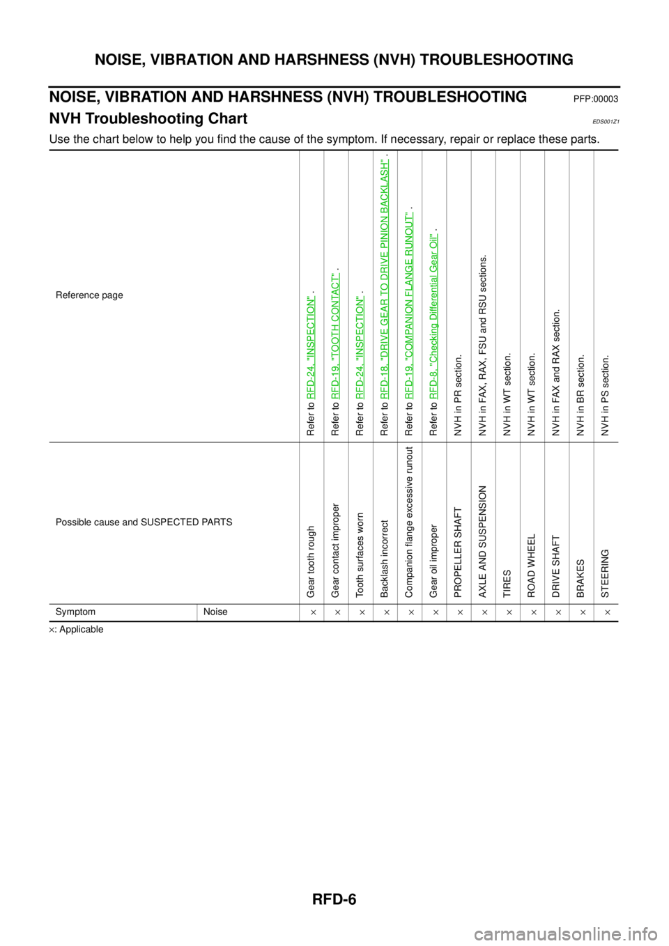
NVH Troubleshooting ChartEDS001Z1
Use the chart below to help you find the cause of the symptom. If necessary, repair or replace these parts.
×: ApplicableReference page
Refer to RFD-24, "
INSPECTION
" .
Refer to RFD-19, "
TOOTH CONTACT
" .
Refer to RFD-24, "
INSPECTION
" .
Refer to RFD-18, "
DRIVE GEAR TO DRIVE PINION BACKLASH
" .
Refer to RFD-19, "
COMPANION FLANGE RUNOUT
" .
Refer to RFD-8, "
Checking Differential Gear Oil
" .
NVH in PR section.
NVH in FAX, RAX, FSU and RSU sections.
NVH in WT section.
NVH in WT section.
NVH in FAX and RAX section.
NVH in BR section.
NVH in PS section.
Possible cause and SUSPECTED PARTS
Gear tooth rough
Gear contact improper
Tooth surfaces worn
Backlash incorrect
Companion flange excessive runout
Gear oil improper
PROPELLER SHAFT
AXLE AND SUSPENSION
TIRES
ROAD WHEEL
DRIVE SHAFT
BRAKES
STEERING
Symptom Noise×××××××××××××
Page 2898 of 4555
RFD-8
DIFFERENTIAL GEAR OIL
DIFFERENTIAL GEAR OILPFP:KLD30
Changing Differential Gear OilEDS0027G
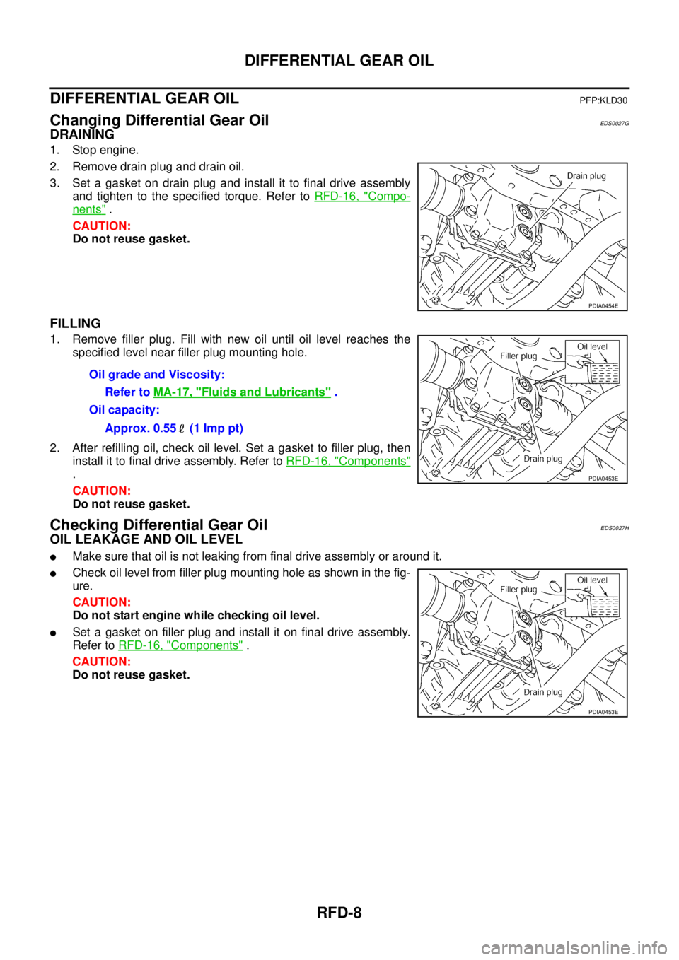
DRAINING
1. Stop engine.
2. Remove drain plug and drain oil.
3. Set a gasket on drain plug and install it to final drive assembly
and tighten to the specified torque. Refer to RFD-16, "
Compo-
nents" .
CAUTION:
Do not reuse gasket.
FILLING
1. Remove filler plug. Fill with new oil until oil level reaches the
specified level near filler plug mounting hole.
2. After refilling oil, check oil level. Set a gasket to filler plug, then
install it to final drive assembly. Refer to RFD-16, "
Components"
.
CAUTION:
Do not reuse gasket.
Checking Differential Gear OilEDS0027H
OIL LEAKAGE AND OIL LEVEL
�Make sure that oil is not leaking from final drive assembly or around it.
�Check oil level from filler plug mounting hole as shown in the fig-
ure.
CAUTION:
Do not start engine while checking oil level.
�Set a gasket on filler plug and install it on final drive assembly.
Refer to RFD-16, "
Components" .
CAUTION:
Do not reuse gasket.
PDIA0454E
Oil grade and Viscosity:
Refer to MA-17, "
Fluids and Lubricants" .
Oil capacity:
Approx. 0.55 (1 Imp pt)
PDIA0453E
PDIA0453E
Page 2905 of 4555
REAR FINAL DRIVE ASSEMBLY
RFD-15
C
E
F
G
H
I
J
K
L
MA
B
RFD
INSTALLATION
Note the following, and install in the reverse order of removal.
�Refer to RFD-16, "Components" about each tightening torque.
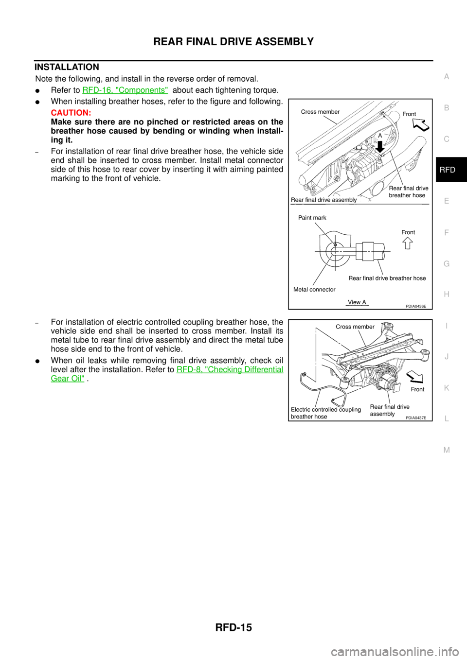
�When installing breather hoses, refer to the figure and following.
CAUTION:
Make sure there are no pinched or restricted areas on the
breather hose caused by bending or winding when install-
ing it.
–For installation of rear final drive breather hose, the vehicle side
end shall be inserted to cross member. Install metal connector
side of this hose to rear cover by inserting it with aiming painted
marking to the front of vehicle.
–For installation of electric controlled coupling breather hose, the
vehicle side end shall be inserted to cross member. Install its
metal tube to rear final drive assembly and direct the metal tube
hose side end to the front of vehicle.
�When oil leaks while removing final drive assembly, check oil
level after the installation. Refer to RFD-8, "
Checking Differential
Gear Oil" .
PDIA0436E
PDIA0437E
Page 2906 of 4555
RFD-16
REAR FINAL DRIVE ASSEMBLY
ComponentsEDS001ZB
PDIA0932E
1. Companion flange lock nut 2. Companion flange 3. Front oil seal
4. Coupling cover 5. Connector bracket 6. Reamer bolt
7. Coupling front bearing 8. Bearing shim 9. Electric controlled coupling
10. 4WD solenoid harness 11. Center oil seal 12. Drive pinion nut
13. Pinion front bearing 14. Carrier case 15. Collapsible spacer
16. Drive pinion adjusting shim 17. Pinion rear bearing 18. Drive pinion
19. Side oil seal 20. Side bearing adjusting shim 21. Side bearing
22. Drive gear 23. Differential case 24. Side gear thrust washer
25. Side gear 26. Pinion mate thrust washer 27. Pinion mate gear
28. Pinion mate shaft 29. Lock pin 30. Rear cover
31. Filler plug 32. Drain plug 33. Gasket
Page 2908 of 4555
RFD-18
REAR FINAL DRIVE ASSEMBLY
DRIVE GEAR TO DRIVE PINION BACKLASH
1. Drain the oil.
2. Remove the rear cover. Refer to RFD-22, "
Removal of Differential Assembly" .
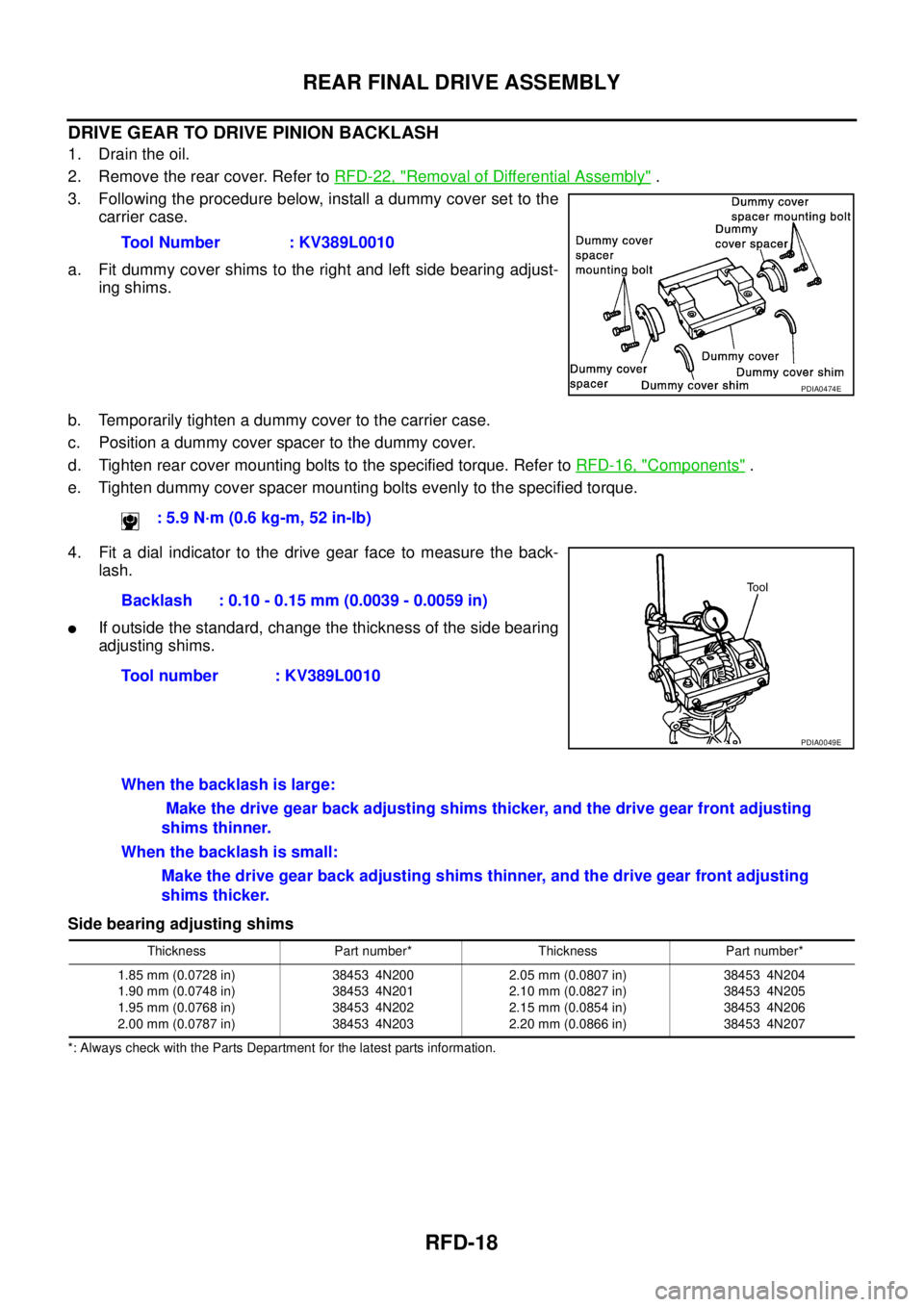
3. Following the procedure below, install a dummy cover set to the
carrier case.
a. Fit dummy cover shims to the right and left side bearing adjust-
ing shims.
b. Temporarily tighten a dummy cover to the carrier case.
c. Position a dummy cover spacer to the dummy cover.
d. Tighten rear cover mounting bolts to the specified torque. Refer to RFD-16, "
Components" .
e. Tighten dummy cover spacer mounting bolts evenly to the specified torque.
4. Fit a dial indicator to the drive gear face to measure the back-
lash.
�If outside the standard, change the thickness of the side bearing
adjusting shims.
Side bearing adjusting shims
*: Always check with the Parts Department for the latest parts information.
Tool Number : KV389L0010
PDIA0474E
: 5.9 N·m (0.6 kg-m, 52 in-lb)
Backlash : 0.10 - 0.15 mm (0.0039 - 0.0059 in)
Tool number : KV389L0010
PDIA0049E
When the backlash is large:
Make the drive gear back adjusting shims thicker, and the drive gear front adjusting
shims thinner.
When the backlash is small:
Make the drive gear back adjusting shims thinner, and the drive gear front adjusting
shims thicker.
Thickness Part number* Thickness Part number*
1.85 mm (0.0728 in)
1.90 mm (0.0748 in)
1.95 mm (0.0768 in)
2.00 mm (0.0787 in)38453 4N200
38453 4N201
38453 4N202
38453 4N2032.05 mm (0.0807 in)
2.10 mm (0.0827 in)
2.15 mm (0.0854 in)
2.20 mm (0.0866 in)38453 4N204
38453 4N205
38453 4N206
38453 4N207
Page 2909 of 4555
REAR FINAL DRIVE ASSEMBLY
RFD-19
C
E
F
G
H
I
J
K
L
MA
B
RFD
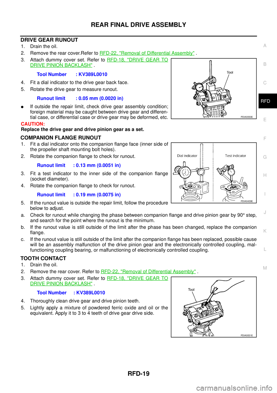
DRIVE GEAR RUNOUT
1. Drain the oil.
2. Remove the rear cover.Refer to RFD-22, "
Removal of Differential Assembly" .
3. Attach dummy cover set. Refer to RFD-18, "
DRIVE GEAR TO
DRIVE PINION BACKLASH" .
4. Fit a dial indicator to the drive gear back face.
5. Rotate the drive gear to measure runout.
�If outside the repair limit, check drive gear assembly condition;
foreign material may be caught between drive gear and differen-
tial case, or differential case or drive gear may be deformed, etc.
CAUTION:
Replace the drive gear and drive pinion gear as a set.
COMPANION FLANGE RUNOUT
1. Fit a dial indicator onto the companion flange face (inner side of
the propeller shaft mounting bolt holes).
2. Rotate the companion flange to check for runout.
3. Fit a test indicator to the inner side of the companion flange
(socket diameter).
4. Rotate the companion flange to check for runout.
5. If the runout value is outside the repair limit, follow the procedure
below to adjust.
a. Check for runout while changing the phase between companion flange and drive pinion gear by 90° step,
and search for the point where the runout is the minimum.
b. If the runout value is still outside of the limit after the phase has been changed, replace the companion
flange.
c. If the runout value is still outside of the limit after the companion flange has been replaced, possible cause
will be an assembly malfunction of the drive pinion gear and the electronically controlled coupling, mal-
functioning coupling bearing, or malfunctioning of electronically controlled coupling.
TOOTH CONTACT
1. Drain the oil.
2. Remove the rear cover. Refer to RFD-22, "
Removal of Differential Assembly" .
3. Attach dummy cover set. Refer to RFD-18, "
DRIVE GEAR TO
DRIVE PINION BACKLASH" .
4. Thoroughly clean drive gear and drive pinion teeth.
5. Lightly apply a mixture of powdered ferric oxide and oil or the
equivalent. Apply it to 3 to 4 teeth of drive gear drive side.Tool Number : KV389L0010
Runout limit : 0.05 mm (0.0020 in)
PDIA0050E
Runout limit : 0.13 mm (0.0051 in)
Runout limit : 0.19 mm (0.0075 in)
PDIA0439E
Tool Number : KV389L0010
PDIA0051E
Page 2912 of 4555
RFD-22
REAR FINAL DRIVE ASSEMBLY
Disassembly and AssemblyEDS001ZD
DISASSEMBLY
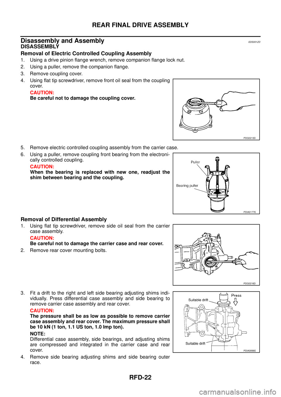
Removal of Electric Controlled Coupling Assembly
1. Using a drive pinion flange wrench, remove companion flange lock nut.
2. Using a puller, remove the companion flange.
3. Remove coupling cover.
4. Using flat tip screwdriver, remove front oil seal from the coupling
cover.
CAUTION:
Be careful not to damage the coupling cover.
5. Remove electric controlled coupling assembly from the carrier case.
6. Using a puller, remove coupling front bearing from the electroni-
cally controlled coupling.
CAUTION:
When the bearing is replaced with new one, readjust the
shim between bearing and the coupling.
Removal of Differential Assembly
1. Using flat tip screwdriver, remove side oil seal from the carrier
case assembly.
CAUTION:
Be careful not to damage the carrier case and rear cover.
2. Remove rear cover mounting bolts.
3. Fit a drift to the right and left side bearing adjusting shims indi-
vidually. Press differential case assembly and side bearing to
remove carrier case assembly and rear cover.
CAUTION:
The pressure shall be as low as possible to remove carrier
case assembly and rear cover. The maximum pressure shall
be 10 kN (1 ton, 1.1 US ton, 1.0 Imp ton).
NOTE:
Differential case assembly, side bearings, and adjusting shims
are compressed and integrated in the carrier case and rear
cover.
4. Remove side bearing adjusting shims and side bearing outer
race.
PDG0213D
PDIA0177E
PDG0216D
PDIA0896E
Page 2913 of 4555
REAR FINAL DRIVE ASSEMBLY
RFD-23
C
E
F
G
H
I
J
K
L
MA
B
RFD
CAUTION:
Mark the side bearing adjusting shims so that the original mounting positions (right/left) can be
identified later.
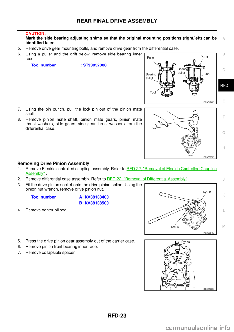
5. Remove drive gear mounting bolts, and remove drive gear from the differential case.
6. Using a puller and the drift below, remove side bearing inner
race.
7. Using the pin punch, pull the lock pin out of the pinion mate
shaft.
8. Remove pinion mate shaft, pinion mate gears, pinion mate
thrust washers, side gears, side gear thrust washers from the
differential case.
Removing Drive Pinion Assembly
1. Remove Electric controlled coupling assembly. Refer to RFD-22, "Removal of Electric Controlled Coupling
Assembly" .
2. Remove differential case assembly. Refer to RFD-22, "
Removal of Differential Assembly" .
3. Fit the drive pinion socket onto the drive pinion spline. Using the
pinion nut wrench, remove drive pinion nut.
4. Remove center oil seal.
5. Press the drive pinion gear assembly out of the carrier case.
6. Remove pinion front bearing inner race.
7. Remove collapsible spacer.Tool number : ST33052000
PDIA0178E
PDIA0897E
Tool number A: KV38108400
B: KV38108500
PDIA0054E
SDIA0576E