Page 2692 of 4555
AT-428
[ALL]
DISASSEMBLY
24. Remove converter housing according to the following proce-
dures.
a. Remove converter housing mounting bolts.
b. Remove converter housing by tapping it lightly.
c. Remove O-ring from differential oil port.
25. Remove final drive assembly from transaxle case.
26. Remove differential side bearing outer race.
27. Remove differential side bearing adjusting shim from transaxle
case.
ATM0024D
SCIA3281E
SAT228F
SAT010FC
SCIA4742E
Page 2693 of 4555
DISASSEMBLY
AT-429
[ALL]
D
E
F
G
H
I
J
K
L
MA
B
AT
28. Remove differential side bearing outer race from converter
housing.
29. Remove RH differential side oil seal with flat-bladed screwdriver
from converter housing.
CAUTION:
Be careful not to damage converter housing.
30. Remove differential lubricant tube from converter housing.
31. Remove oil pump assembly according to the following procedures.
a. Remove O-ring from input shaft assembly (high clutch drum).
SAT011FC
SCIA3283E
SAT063K
SCIA2979E
Page 2703 of 4555
DISASSEMBLY
AT-439
[ALL]
D
E
F
G
H
I
J
K
L
MA
B
AT
45. Remove return spring and parking pawl spacer with flat-bladed
screwdriver from parking shaft.
46. Draw out parking shaft and remove parking pawl from transaxle
case.
47. Check parking pawl and shaft for damage or wear.
48. Remove parking actuator support from transaxle case.
49. Check parking actuator support for damage or wear.
50. Remove LH differential side oil seal with flat-bladed screwdriver
from transaxle case.
CAUTION:
Be careful not to scratch transaxle case.
SCIA4881E
SAT066D
SAT040F
Page 2767 of 4555
REPAIR FOR COMPONENT PARTS
AT-503
[ALL]
D
E
F
G
H
I
J
K
L
MA
B
AT
Final DriveECS00ECB
COMPONENTS
DISASSEMBLY
1. Remove final gear.
2. Press out differential side bearings.
CAUTION:
Be careful not to mix up the right and left bearings.
1. Pinion mate gear 2. Pinion mate gear thrust washer 3. Pinion mate shaft
4. Lock pin 5. Side gear 6. Side gear thrust washer
7. Differential side bearing 8. Differential case 9. Final gear
10. Differential side bearing 11. Differential side bearing adjusting
shim
SCIA3346E
SMT505B
SMT744AA
Page 2768 of 4555
AT-504
[ALL]
REPAIR FOR COMPONENT PARTS
3. Remove differential side bearing outer race, and side bearing
adjusting shim from transaxle case.
4. Drive out lock pin.
5. Draw out pinion mate shaft.
6. Remove pinion mate gears, pinion mate gear thrust washers,
side gears and side gear thrust washers.
INSPECTION
Gear, Washer, Shaft and Case
�Check mating surfaces of differential case, side gears, pinion
mate gears and pinion mate shaft.
�Check washers for wear.
SAT010FA
SAT904DA
SAT316D
SAT544F
Page 2769 of 4555
REPAIR FOR COMPONENT PARTS
AT-505
[ALL]
D
E
F
G
H
I
J
K
L
MA
B
AT
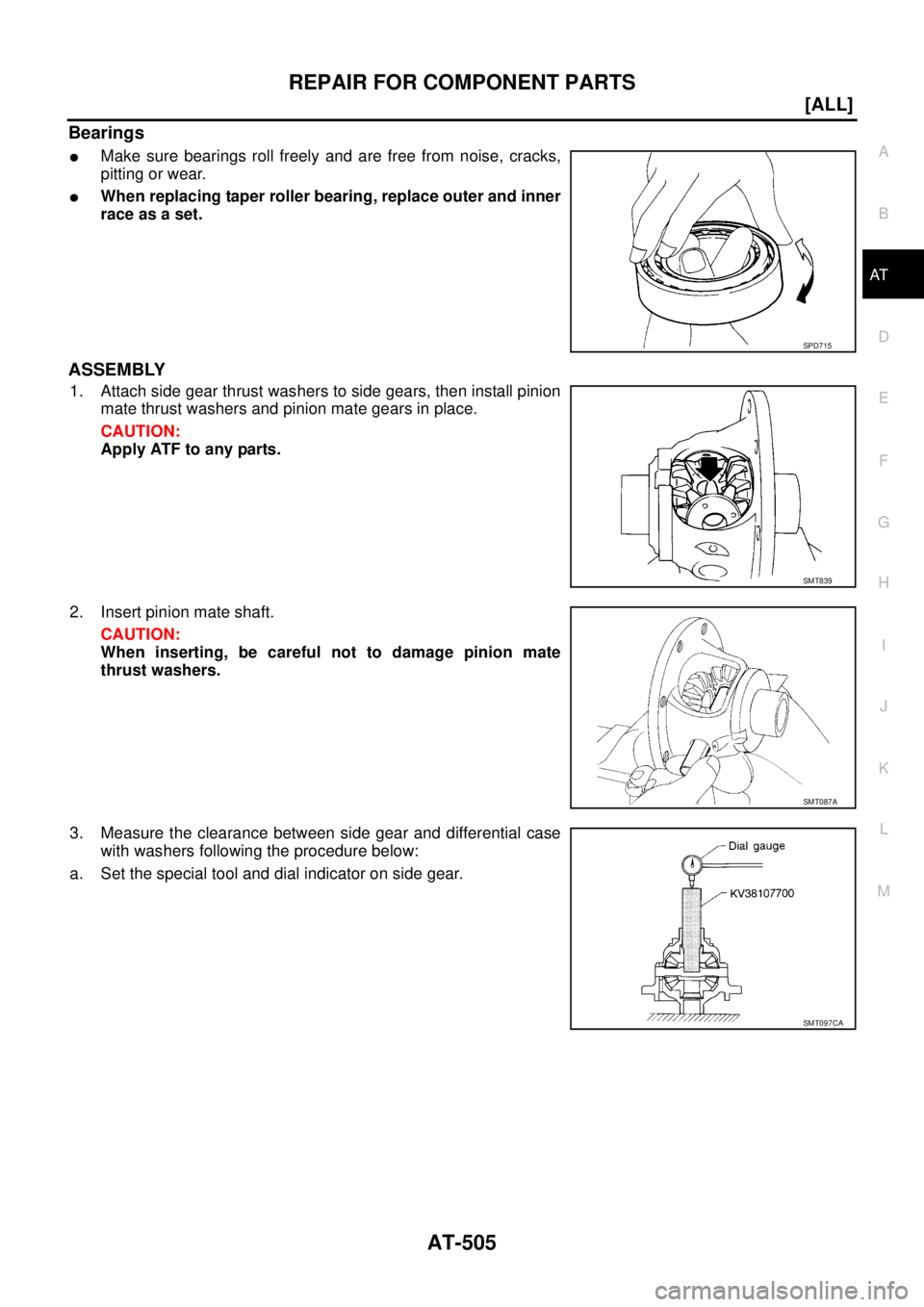
Bearings
�Make sure bearings roll freely and are free from noise, cracks,
pitting or wear.
�When replacing taper roller bearing, replace outer and inner
race as a set.
ASSEMBLY
1. Attach side gear thrust washers to side gears, then install pinion
mate thrust washers and pinion mate gears in place.
CAUTION:
Apply ATF to any parts.
2. Insert pinion mate shaft.
CAUTION:
When inserting, be careful not to damage pinion mate
thrust washers.
3. Measure the clearance between side gear and differential case
with washers following the procedure below:
a. Set the special tool and dial indicator on side gear.
SPD715
SMT839
SMT087A
SMT097CA
Page 2770 of 4555
AT-506
[ALL]
REPAIR FOR COMPONENT PARTS
b. Move side gear up and down to measure dial indicator deflec-
tion. Always measure indicator deflection on both side gears.
c. If not within specification, adjust the clearance by changing the
thickness of differential side gear thrust washers. Refer to AT-
535, "Final Drive" .
4. Install lock pin.
CAUTION:
�Do not reuse lock pin.
�Make sure that lock pin is flush with case.
5. Press on differential side bearings.
CAUTION:
Apply ATF to differential side bearings.
6. Install differential side bearing outer race and differential side
bearing adjusting shim on transaxle case. Refer to AT- 5 0 8 ,
"Adjustment (1)" .
7. Tighten final gear and tighten fixing bolts to the specified torque
in numerical order shown in the figure after temporarily tighten-
ing them. Refer to AT- 5 0 3 , "
COMPONENTS" . Clearance between side gear and differential case
with washer:
0.1 - 0.2 mm (0.004 - 0.008 in)
SMT611A
SMT699BA
SAT545FA
ATM0432D
Page 2771 of 4555
ASSEMBLY
AT-507
[ALL]
D
E
F
G
H
I
J
K
L
MA
B
AT
ASSEMBLYPFP:00000
Assembly (1)ECS004MD
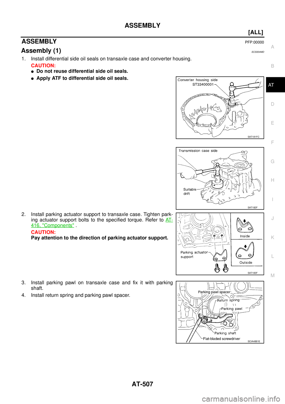
1. Install differential side oil seals on transaxle case and converter housing.
CAUTION:
�Do not reuse differential side oil seals.
�Apply ATF to differential side oil seals.
2. Install parking actuator support to transaxle case. Tighten park-
ing actuator support bolts to the specified torque. Refer to AT-
416, "Components" .
CAUTION:
Pay attention to the direction of parking actuator support.
3. Install parking pawl on transaxle case and fix it with parking
shaft.
4. Install return spring and parking pawl spacer.
SAT181FC
SAT182F
SAT183F
SCIA4881E
![NISSAN X-TRAIL 2005 Service Repair Manual AT-428
[ALL]
DISASSEMBLY
24. Remove converter housing according to the following proce-
dures.
a. Remove converter housing mounting bolts.
b. Remove converter housing by tapping it lightly.
c. Remov](/manual-img/5/57403/w960_57403-2691.png "NISSAN X-TRAIL 2005 Service Repair Manual AT-428
[ALL]
DISASSEMBLY
24. Remove converter housing according to the following proce-
dures.
a. Remove converter housing mounting bolts.
b. Remove converter housing by tapping it lightly.
c. Remov")
![NISSAN X-TRAIL 2005 Service Repair Manual DISASSEMBLY
AT-429
[ALL]
D
E
F
G
H
I
J
K
L
MA
B
AT
28. Remove differential side bearing outer race from converter
housing.
29. Remove RH differential side oil seal with flat-bladed screwdriver
from](/manual-img/5/57403/w960_57403-2692.png "NISSAN X-TRAIL 2005 Service Repair Manual DISASSEMBLY
AT-429
[ALL]
D
E
F
G
H
I
J
K
L
MA
B
AT
28. Remove differential side bearing outer race from converter
housing.
29. Remove RH differential side oil seal with flat-bladed screwdriver
from")
![NISSAN X-TRAIL 2005 Service Repair Manual DISASSEMBLY
AT-439
[ALL]
D
E
F
G
H
I
J
K
L
MA
B
AT
45. Remove return spring and parking pawl spacer with flat-bladed
screwdriver from parking shaft.
46. Draw out parking shaft and remove parking paw](/manual-img/5/57403/w960_57403-2702.png "NISSAN X-TRAIL 2005 Service Repair Manual DISASSEMBLY
AT-439
[ALL]
D
E
F
G
H
I
J
K
L
MA
B
AT
45. Remove return spring and parking pawl spacer with flat-bladed
screwdriver from parking shaft.
46. Draw out parking shaft and remove parking paw")
![NISSAN X-TRAIL 2005 Service Repair Manual REPAIR FOR COMPONENT PARTS
AT-503
[ALL]
D
E
F
G
H
I
J
K
L
MA
B
AT
Final DriveECS00ECB
COMPONENTS
DISASSEMBLY
1. Remove final gear.
2. Press out differential side bearings.
CAUTION:
Be careful not to](/manual-img/5/57403/w960_57403-2766.png "NISSAN X-TRAIL 2005 Service Repair Manual REPAIR FOR COMPONENT PARTS
AT-503
[ALL]
D
E
F
G
H
I
J
K
L
MA
B
AT
Final DriveECS00ECB
COMPONENTS
DISASSEMBLY
1. Remove final gear.
2. Press out differential side bearings.
CAUTION:
Be careful not to")
![NISSAN X-TRAIL 2005 Service Repair Manual AT-504
[ALL]
REPAIR FOR COMPONENT PARTS
3. Remove differential side bearing outer race, and side bearing
adjusting shim from transaxle case.
4. Drive out lock pin.
5. Draw out pinion mate shaft.
6.](/manual-img/5/57403/w960_57403-2767.png "NISSAN X-TRAIL 2005 Service Repair Manual AT-504
[ALL]
REPAIR FOR COMPONENT PARTS
3. Remove differential side bearing outer race, and side bearing
adjusting shim from transaxle case.
4. Drive out lock pin.
5. Draw out pinion mate shaft.
6.")
![NISSAN X-TRAIL 2005 Service Repair Manual AT-506
[ALL]
REPAIR FOR COMPONENT PARTS
b. Move side gear up and down to measure dial indicator deflec-
tion. Always measure indicator deflection on both side gears.
c. If not within specification,](/manual-img/5/57403/w960_57403-2769.png "NISSAN X-TRAIL 2005 Service Repair Manual AT-506
[ALL]
REPAIR FOR COMPONENT PARTS
b. Move side gear up and down to measure dial indicator deflec-
tion. Always measure indicator deflection on both side gears.
c. If not within specification,")