Page 2205 of 4555
TRANSAXLE ASSEMBLY
MT-49
D
E
F
G
H
I
J
K
L
MA
B
MT
3. Install oil channel on mainshaft side.
CAUTION:
Be careful with the orientation of installation.
4. Install mainshaft front bearing to clutch housing using the drift.
CAUTION:
Be careful with the orientation of installation.
5. Install mainshaft bearing retainer to clutch housing and tighten
mounting bolt to the specified torque. Refer to MT-41, "
Gear
Components" .
CAUTION:
Install with punched surface facing up.
6. Install differential side bearing outer race to clutch housing using
the drifts.
7. Install final drive assembly into clutch housing.
SCIA0986E
SCIA0401E
PCIB0789E
SCIA0987E
SCIA0888E
Page 2207 of 4555
TRANSAXLE ASSEMBLY
MT-51
D
E
F
G
H
I
J
K
L
MA
B
MT
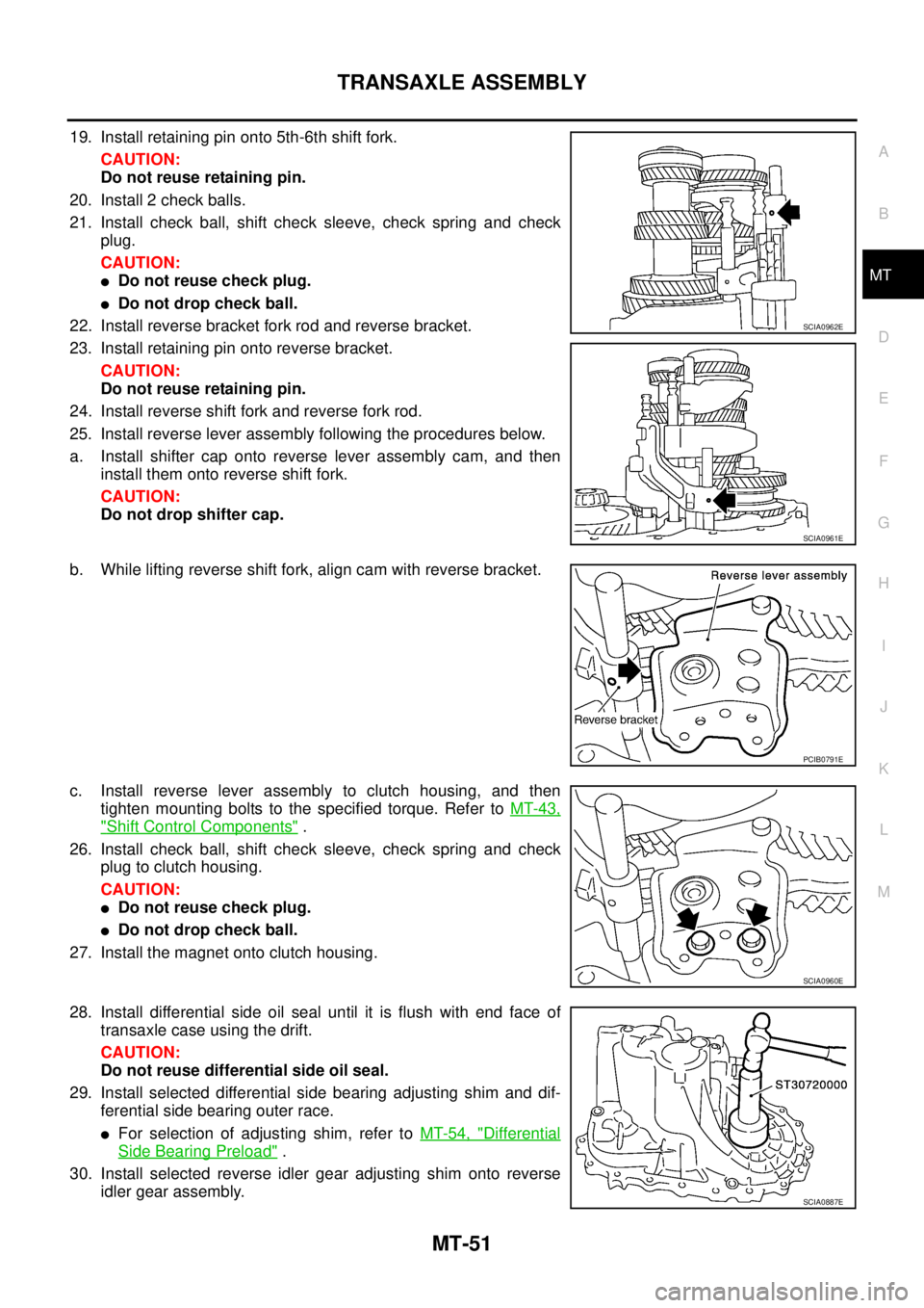
19. Install retaining pin onto 5th-6th shift fork.
CAUTION:
Do not reuse retaining pin.
20. Install 2 check balls.
21. Install check ball, shift check sleeve, check spring and check
plug.
CAUTION:
�Do not reuse check plug.
�Do not drop check ball.
22. Install reverse bracket fork rod and reverse bracket.
23. Install retaining pin onto reverse bracket.
CAUTION:
Do not reuse retaining pin.
24. Install reverse shift fork and reverse fork rod.
25. Install reverse lever assembly following the procedures below.
a. Install shifter cap onto reverse lever assembly cam, and then
install them onto reverse shift fork.
CAUTION:
Do not drop shifter cap.
b. While lifting reverse shift fork, align cam with reverse bracket.
c. Install reverse lever assembly to clutch housing, and then
tighten mounting bolts to the specified torque. Refer to MT-43,
"Shift Control Components" .
26. Install check ball, shift check sleeve, check spring and check
plug to clutch housing.
CAUTION:
�Do not reuse check plug.
�Do not drop check ball.
27. Install the magnet onto clutch housing.
28. Install differential side oil seal until it is flush with end face of
transaxle case using the drift.
CAUTION:
Do not reuse differential side oil seal.
29. Install selected differential side bearing adjusting shim and dif-
ferential side bearing outer race.
�For selection of adjusting shim, refer to MT-54, "Differential
Side Bearing Preload" .
30. Install selected reverse idler gear adjusting shim onto reverse
idler gear assembly.
SCIA0962E
SCIA0961E
PCIB0791E
SCIA0960E
SCIA0887E
Page 2210 of 4555
MT-54
TRANSAXLE ASSEMBLY
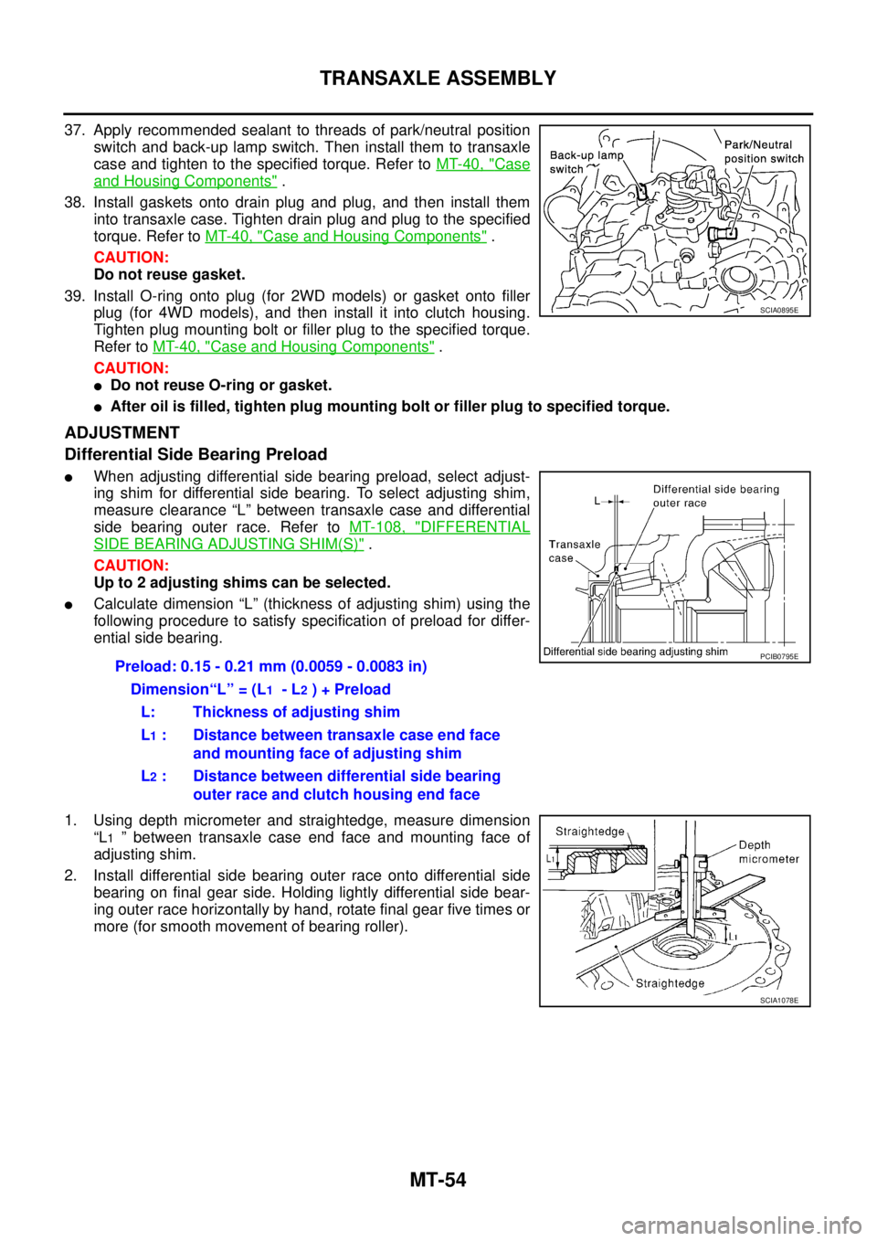
37. Apply recommended sealant to threads of park/neutral position
switch and back-up lamp switch. Then install them to transaxle
case and tighten to the specified torque. Refer to MT-40, "
Case
and Housing Components" .
38. Install gaskets onto drain plug and plug, and then install them
into transaxle case. Tighten drain plug and plug to the specified
torque. Refer to MT-40, "
Case and Housing Components" .
CAUTION:
Do not reuse gasket.
39. Install O-ring onto plug (for 2WD models) or gasket onto filler
plug (for 4WD models), and then install it into clutch housing.
Tighten plug mounting bolt or filler plug to the specified torque.
Refer to MT-40, "
Case and Housing Components" .
CAUTION:
�Do not reuse O-ring or gasket.
�After oil is filled, tighten plug mounting bolt or filler plug to specified torque.
ADJUSTMENT
Differential Side Bearing Preload
�When adjusting differential side bearing preload, select adjust-
ing shim for differential side bearing. To select adjusting shim,
measure clearance “L” between transaxle case and differential
side bearing outer race. Refer to MT-108, "
DIFFERENTIAL
SIDE BEARING ADJUSTING SHIM(S)" .
CAUTION:
Up to 2 adjusting shims can be selected.
�Calculate dimension “L” (thickness of adjusting shim) using the
following procedure to satisfy specification of preload for differ-
ential side bearing.
1. Using depth micrometer and straightedge, measure dimension
“L
1 ” between transaxle case end face and mounting face of
adjusting shim.
2. Install differential side bearing outer race onto differential side
bearing on final gear side. Holding lightly differential side bear-
ing outer race horizontally by hand, rotate final gear five times or
more (for smooth movement of bearing roller).
SCIA0895E
Preload: 0.15 - 0.21 mm (0.0059 - 0.0083 in)
Dimension“L” = (L
1 - L2 ) + Preload
L: Thickness of adjusting shim
L
1 : Distance between transaxle case end face
and mounting face of adjusting shim
L
2 : Distance between differential side bearing
outer race and clutch housing end face
PCIB0795E
SCIA1078E
Page 2211 of 4555
TRANSAXLE ASSEMBLY
MT-55
D
E
F
G
H
I
J
K
L
MA
B
MT
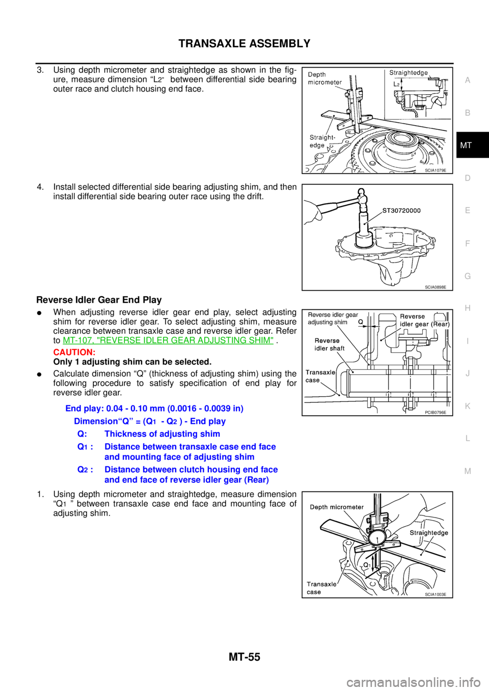
3. Using depth micrometer and straightedge as shown in the fig-
ure, measure dimension “L
2” between differential side bearing
outer race and clutch housing end face.
4. Install selected differential side bearing adjusting shim, and then
install differential side bearing outer race using the drift.
Reverse Idler Gear End Play
�When adjusting reverse idler gear end play, select adjusting
shim for reverse idler gear. To select adjusting shim, measure
clearance between transaxle case and reverse idler gear. Refer
to MT-107, "
REVERSE IDLER GEAR ADJUSTING SHIM" .
CAUTION:
Only 1 adjusting shim can be selected.
�Calculate dimension “Q” (thickness of adjusting shim) using the
following procedure to satisfy specification of end play for
reverse idler gear.
1. Using depth micrometer and straightedge, measure dimension
“Q
1 ” between transaxle case end face and mounting face of
adjusting shim.
SCIA1079E
SCIA0898E
End play: 0.04 - 0.10 mm (0.0016 - 0.0039 in)
Dimension“Q” = (Q
1 - Q2 ) - End play
Q: Thickness of adjusting shim
Q
1 : Distance between transaxle case end face
and mounting face of adjusting shim
Q
2 : Distance between clutch housing end face
and end face of reverse idler gear (Rear)
PCIB0796E
SCIA1003E
Page 2249 of 4555
FINAL DRIVE
MT-93
D
E
F
G
H
I
J
K
L
MA
B
MT
FINAL DRIVEPFP:38411
Disassembly and Assembly (RS5F51A)ECS008CA
PRE-INSPECTION
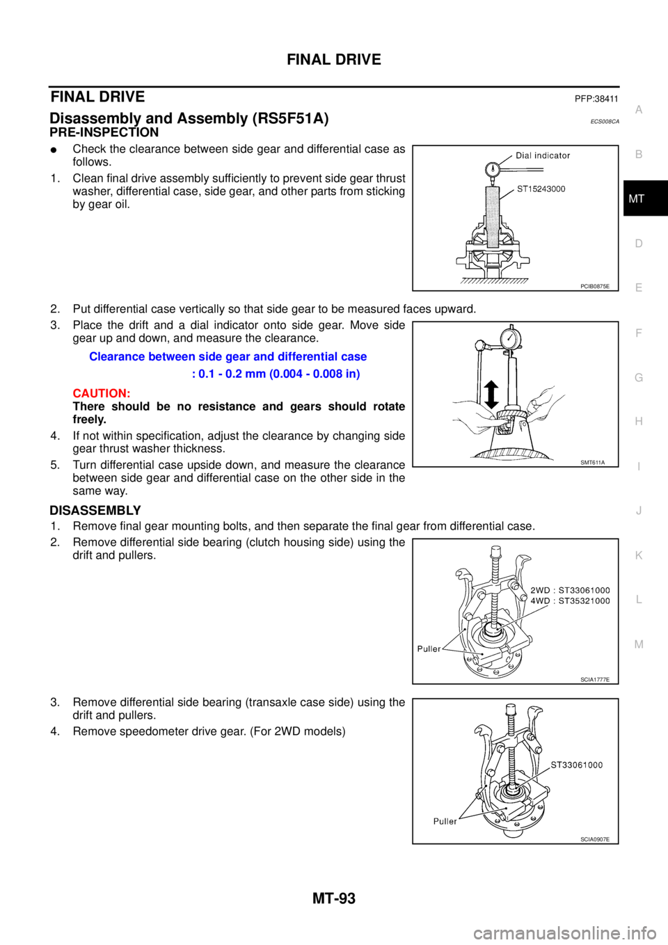
�Check the clearance between side gear and differential case as
follows.
1. Clean final drive assembly sufficiently to prevent side gear thrust
washer, differential case, side gear, and other parts from sticking
by gear oil.
2. Put differential case vertically so that side gear to be measured faces upward.
3. Place the drift and a dial indicator onto side gear. Move side
gear up and down, and measure the clearance.
CAUTION:
There should be no resistance and gears should rotate
freely.
4. If not within specification, adjust the clearance by changing side
gear thrust washer thickness.
5. Turn differential case upside down, and measure the clearance
between side gear and differential case on the other side in the
same way.
DISASSEMBLY
1. Remove final gear mounting bolts, and then separate the final gear from differential case.
2. Remove differential side bearing (clutch housing side) using the
drift and pullers.
3. Remove differential side bearing (transaxle case side) using the
drift and pullers.
4. Remove speedometer drive gear. (For 2WD models)
PCIB0875E
Clearance between side gear and differential case
: 0.1 - 0.2 mm (0.004 - 0.008 in)
SMT611A
SCIA1777E
SCIA0907E
Page 2250 of 4555
MT-94
FINAL DRIVE
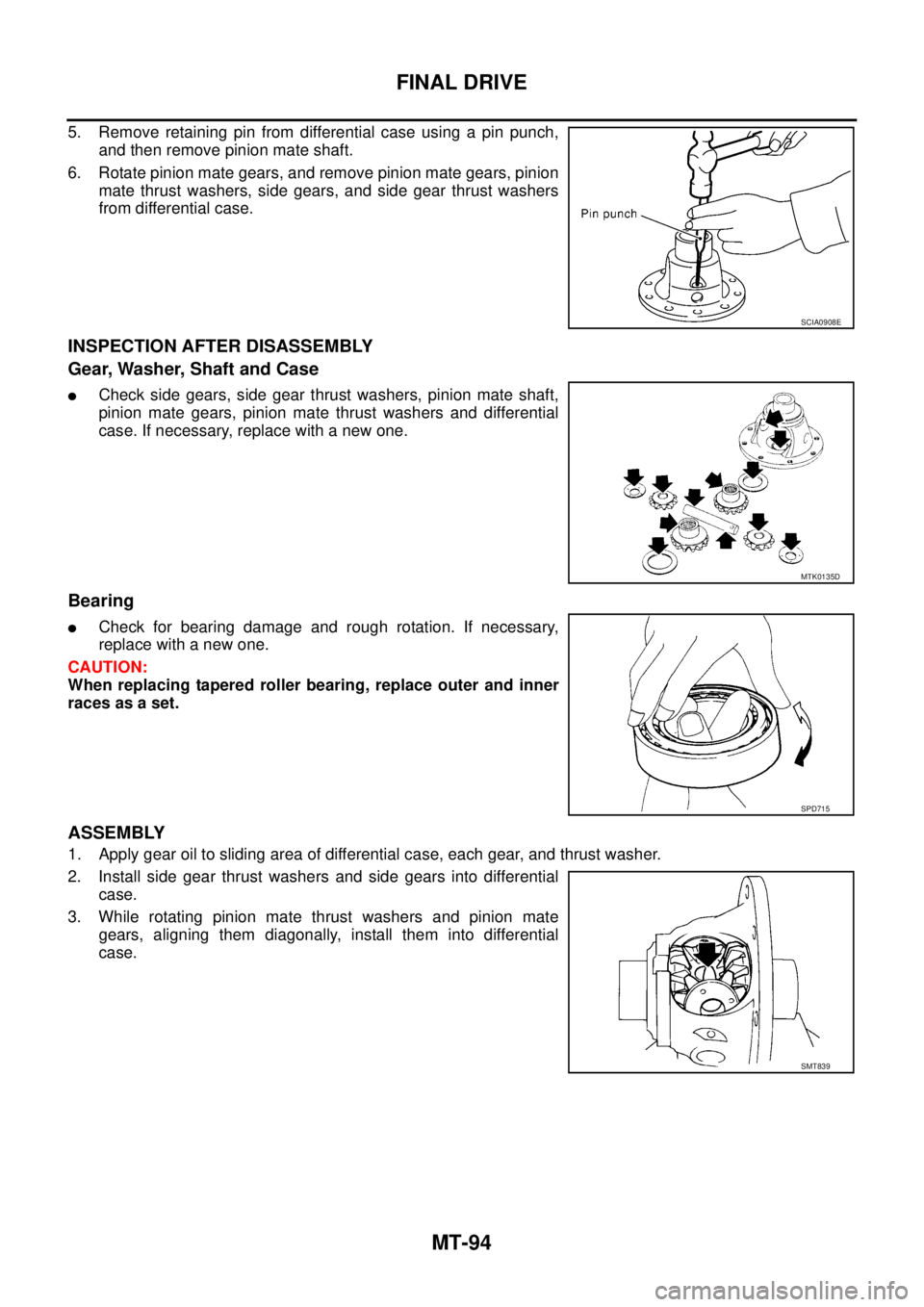
5. Remove retaining pin from differential case using a pin punch,
and then remove pinion mate shaft.
6. Rotate pinion mate gears, and remove pinion mate gears, pinion
mate thrust washers, side gears, and side gear thrust washers
from differential case.
INSPECTION AFTER DISASSEMBLY
Gear, Washer, Shaft and Case
�Check side gears, side gear thrust washers, pinion mate shaft,
pinion mate gears, pinion mate thrust washers and differential
case. If necessary, replace with a new one.
Bearing
�Check for bearing damage and rough rotation. If necessary,
replace with a new one.
CAUTION:
When replacing tapered roller bearing, replace outer and inner
races as a set.
ASSEMBLY
1. Apply gear oil to sliding area of differential case, each gear, and thrust washer.
2. Install side gear thrust washers and side gears into differential
case.
3. While rotating pinion mate thrust washers and pinion mate
gears, aligning them diagonally, install them into differential
case.
SCIA0908E
MTK0135D
SPD715
SMT839
Page 2251 of 4555
FINAL DRIVE
MT-95
D
E
F
G
H
I
J
K
L
MA
B
MT
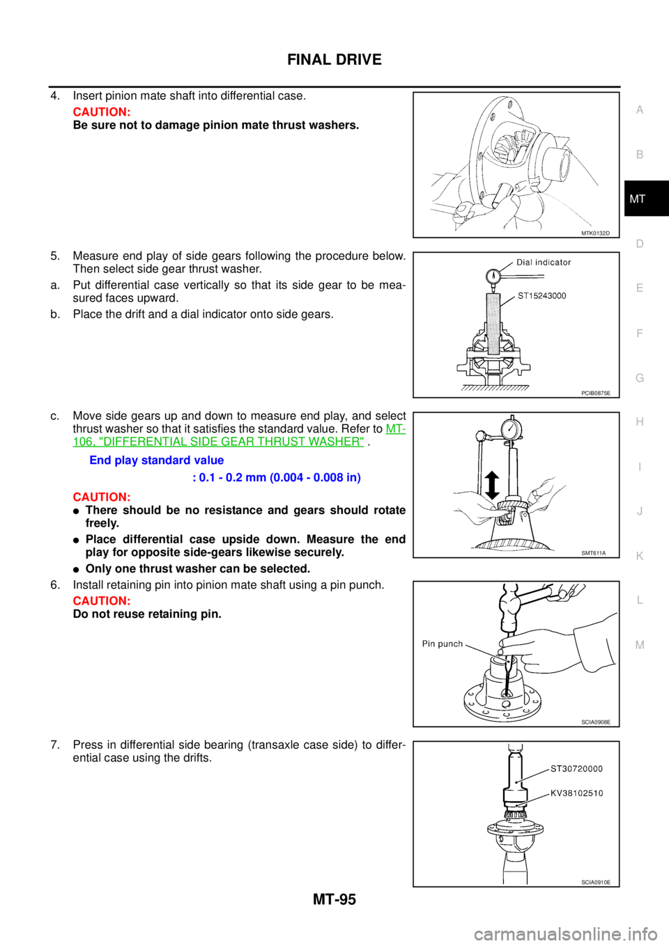
4. Insert pinion mate shaft into differential case.
CAUTION:
Be sure not to damage pinion mate thrust washers.
5. Measure end play of side gears following the procedure below.
Then select side gear thrust washer.
a. Put differential case vertically so that its side gear to be mea-
sured faces upward.
b. Place the drift and a dial indicator onto side gears.
c. Move side gears up and down to measure end play, and select
thrust washer so that it satisfies the standard value. Refer to MT-
106, "DIFFERENTIAL SIDE GEAR THRUST WASHER" .
CAUTION:
�There should be no resistance and gears should rotate
freely.
�Place differential case upside down. Measure the end
play for opposite side-gears likewise securely.
�Only one thrust washer can be selected.
6. Install retaining pin into pinion mate shaft using a pin punch.
CAUTION:
Do not reuse retaining pin.
7. Press in differential side bearing (transaxle case side) to differ-
ential case using the drifts.
MTK0132D
PCIB0875E
End play standard value
: 0.1 - 0.2 mm (0.004 - 0.008 in)
SMT611A
SCIA0908E
SCIA0910E
Page 2252 of 4555
MT-96
FINAL DRIVE
8. Align and install speedometer drive gear onto differential case.
(For 2WD models)
9. Press in differential side bearing (clutch housing side) to differ-
ential case using the drifts.
10. Install final gear into differential case, and tighten final gear
mounting bolts to the specified torque. Refer to MT-26, "
Final
Drive Components" .
SMT842D
SCIA1778E
SCIA0912E