2005 NISSAN X-TRAIL window
[x] Cancel search: windowPage 3613 of 4555
POWER DOOR LOCK SYSTEM
BL-31
C
D
E
F
G
H
J
K
L
MA
B
BL
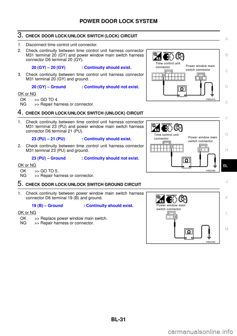
3. CHECK DOOR LOCK/UNLOCK SWITCH (LOCK) CIRCUIT
1. Disconnect time control unit connector.
2. Check continuity between time control unit harness connector
M31 terminal 20 (GY) and power window main switch harness
connector D6 terminal 20 (GY).
3. Check continuity between time control unit harness connector
M31 terminal 20 (GY) and ground.
OK or NG
OK >> GO TO 4.
NG >> Repair harness or connector.
4. CHECK DOOR LOCK/UNLOCK SWITCH (UNLOCK) CIRCUIT
1. Check continuity between time control unit harness connector
M31 terminal 23 (PU) and power window main switch harness
connector D6 terminal 21 (PU).
2. Check continuity between time control unit harness connector
M31 terminal 23 (PU) and ground.
OK or NG
OK >> GO TO 5.
NG >> Repair harness or connector.
5. CHECK DOOR LOCK/UNLOCK SWITCH GROUND CIRCUIT
1. Check continuity between power window main switch harness
connector D6 terminal 19 (B) and ground.
OK or NG
OK >> Replace power window main switch.
NG >> Repair harness or connector.20 (GY) – 20 (GY) : Continuity should exist.
20 (GY) – Ground : Continuity should not exist.
PIIB0347E
23 (PU) – 21 (PU) : Continuity should exist.
23 (PU) – Ground : Continuity should not exist.
PIIB0348E
19 (B) – Ground : Continuity should exist.
PIIB0349E
Page 3615 of 4555
POWER DOOR LOCK SYSTEM
BL-33
C
D
E
F
G
H
J
K
L
MA
B
BL
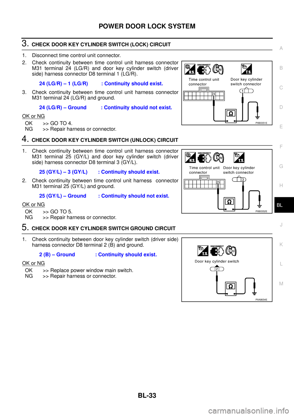
3. CHECK DOOR KEY CYLINDER SWITCH (LOCK) CIRCUIT
1. Disconnect time control unit connector.
2. Check continuity between time control unit harness connector
M31 terminal 24 (LG/R) and door key cylinder switch (driver
side) harness connector D8 terminal 1 (LG/R).
3. Check continuity between time control unit harness connector
M31 terminal 24 (LG/R) and ground.
OK or NG
OK >> GO TO 4.
NG >> Repair harness or connector.
4. CHECK DOOR KEY CYLINDER SWITCH (UNLOCK) CIRCUIT
1. Check continuity between time control unit harness connector
M31 terminal 25 (GY/L) and door key cylinder switch (driver
side) harness connector D8 terminal 3 (GY/L).
2. Check continuity between time control unit harness connector
M31 terminal 25 (GY/L) and ground.
OK or NG
OK >> GO TO 5.
NG >> Repair harness or connector.
5. CHECK DOOR KEY CYLINDER SWITCH GROUND CIRCUIT
1. Check continuity between door key cylinder switch (driver side)
harness connector D8 terminal 2 (B) and ground.
OK or NG
OK >> Replace power window main switch.
NG >> Repair harness or connector.24 (LG/R) – 1 (LG/R) : Continuity should exist.
24 (LG/R) – Ground : Continuity should not exist.
PIIB0351E
25 (GY/L) – 3 (GY/L) : Continuity should exist.
25 (GY/L) – Ground : Continuity should not exist.
PIIB0352E
2 (B) – Ground : Continuity should exist.
PIIA8654E
Page 3638 of 4555
BL-56
POWER DOOR LOCK — SUPER LOCK —
Door Lock/Unlock Switch CheckEIS008EG
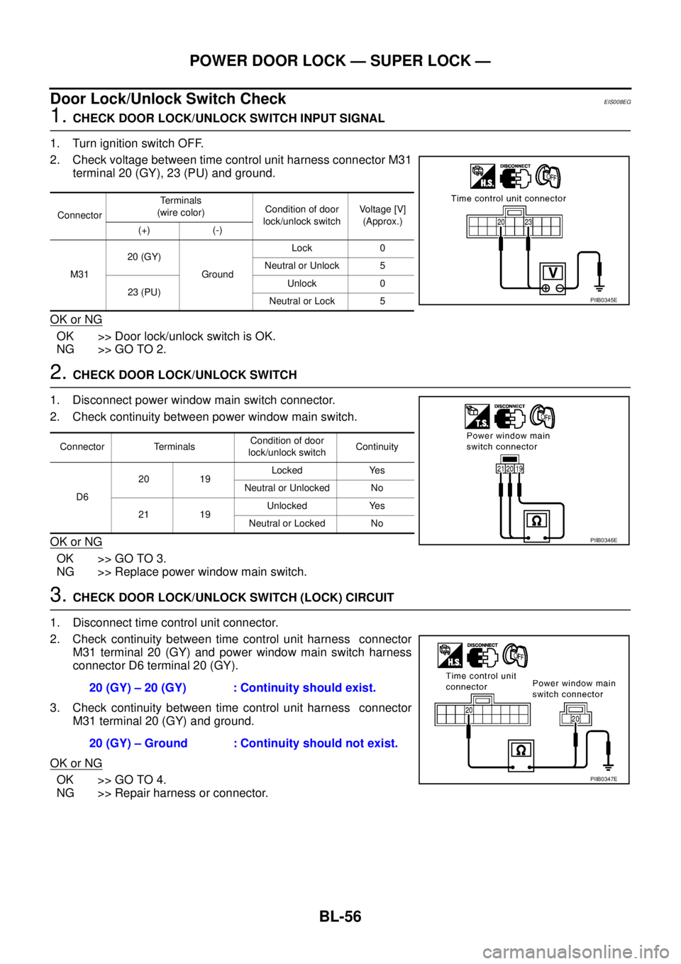
1. CHECK DOOR LOCK/UNLOCK SWITCH INPUT SIGNAL
1. Turn ignition switch OFF.
2. Check voltage between time control unit harness connector M31
terminal 20 (GY), 23 (PU) and ground.
OK or NG
OK >> Door lock/unlock switch is OK.
NG >> GO TO 2.
2. CHECK DOOR LOCK/UNLOCK SWITCH
1. Disconnect power window main switch connector.
2. Check continuity between power window main switch.
OK or NG
OK >> GO TO 3.
NG >> Replace power window main switch.
3. CHECK DOOR LOCK/UNLOCK SWITCH (LOCK) CIRCUIT
1. Disconnect time control unit connector.
2. Check continuity between time control unit harness connector
M31 terminal 20 (GY) and power window main switch harness
connector D6 terminal 20 (GY).
3. Check continuity between time control unit harness connector
M31 terminal 20 (GY) and ground.
OK or NG
OK >> GO TO 4.
NG >> Repair harness or connector.
ConnectorTerminals
(wire color)Condition of door
lock/unlock switchVoltage [V]
(Approx.)
(+) (-)
M3120 (GY)
GroundLock 0
Neutral or Unlock 5
23 (PU)Unlock 0
Neutral or Lock 5
PIIB0345E
Connector TerminalsCondition of door
lock/unlock switchContinuity
D620 19Locked Yes
Neutral or Unlocked No
21 19Unlocked Yes
Neutral or Locked No
PIIB0346E
20 (GY) – 20 (GY) : Continuity should exist.
20 (GY) – Ground : Continuity should not exist.
PIIB0347E
Page 3639 of 4555
POWER DOOR LOCK — SUPER LOCK —
BL-57
C
D
E
F
G
H
J
K
L
MA
B
BL
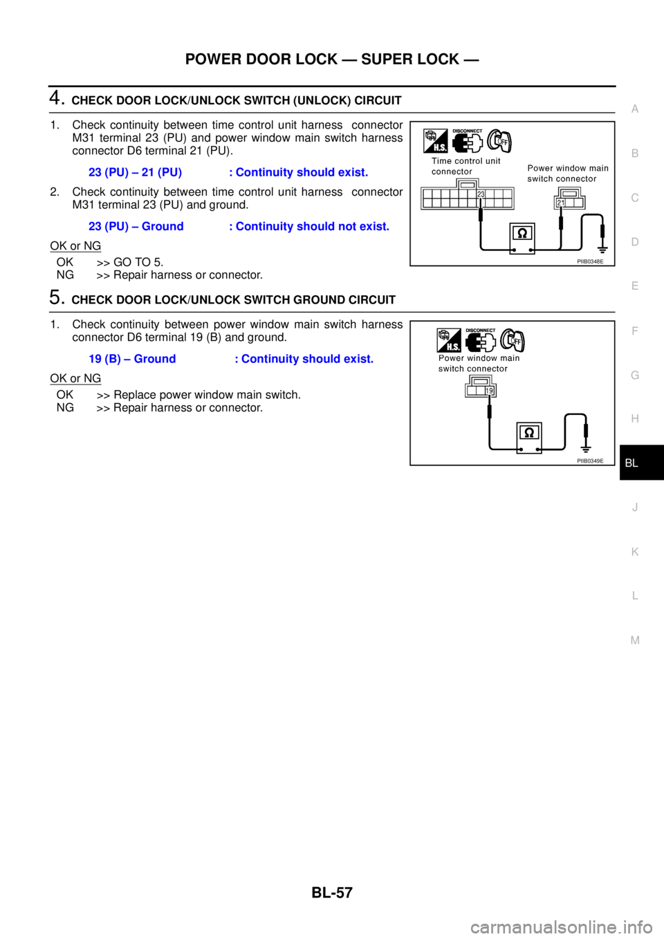
4. CHECK DOOR LOCK/UNLOCK SWITCH (UNLOCK) CIRCUIT
1. Check continuity between time control unit harness connector
M31 terminal 23 (PU) and power window main switch harness
connector D6 terminal 21 (PU).
2. Check continuity between time control unit harness connector
M31 terminal 23 (PU) and ground.
OK or NG
OK >> GO TO 5.
NG >> Repair harness or connector.
5. CHECK DOOR LOCK/UNLOCK SWITCH GROUND CIRCUIT
1. Check continuity between power window main switch harness
connector D6 terminal 19 (B) and ground.
OK or NG
OK >> Replace power window main switch.
NG >> Repair harness or connector.23 (PU) – 21 (PU) : Continuity should exist.
23 (PU) – Ground : Continuity should not exist.
PIIB0348E
19 (B) – Ground : Continuity should exist.
PIIB0349E
Page 3641 of 4555
POWER DOOR LOCK — SUPER LOCK —
BL-59
C
D
E
F
G
H
J
K
L
MA
B
BL
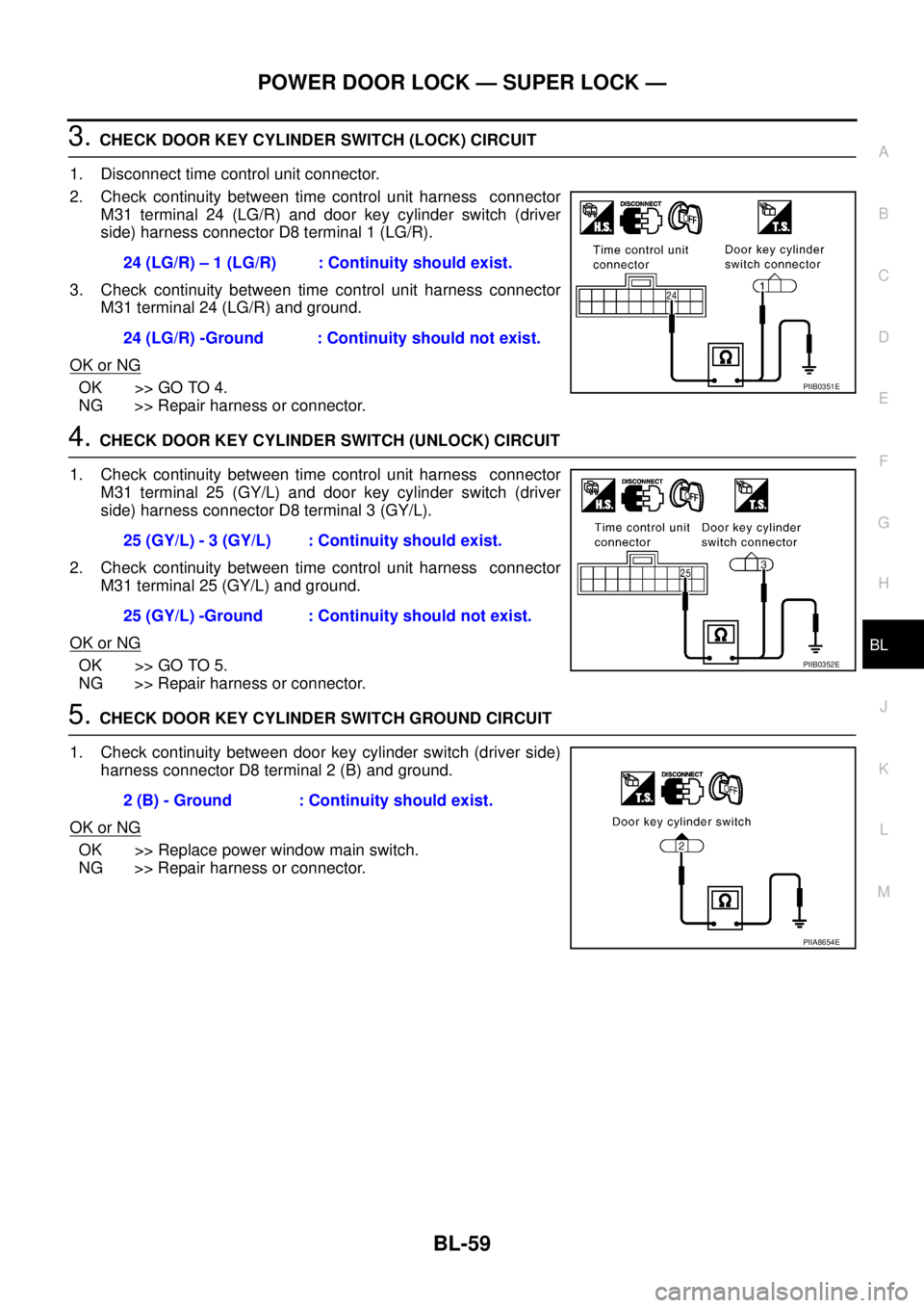
3. CHECK DOOR KEY CYLINDER SWITCH (LOCK) CIRCUIT
1. Disconnect time control unit connector.
2. Check continuity between time control unit harness connector
M31 terminal 24 (LG/R) and door key cylinder switch (driver
side) harness connector D8 terminal 1 (LG/R).
3. Check continuity between time control unit harness connector
M31 terminal 24 (LG/R) and ground.
OK or NG
OK >> GO TO 4.
NG >> Repair harness or connector.
4. CHECK DOOR KEY CYLINDER SWITCH (UNLOCK) CIRCUIT
1. Check continuity between time control unit harness connector
M31 terminal 25 (GY/L) and door key cylinder switch (driver
side) harness connector D8 terminal 3 (GY/L).
2. Check continuity between time control unit harness connector
M31 terminal 25 (GY/L) and ground.
OK or NG
OK >> GO TO 5.
NG >> Repair harness or connector.
5. CHECK DOOR KEY CYLINDER SWITCH GROUND CIRCUIT
1. Check continuity between door key cylinder switch (driver side)
harness connector D8 terminal 2 (B) and ground.
OK or NG
OK >> Replace power window main switch.
NG >> Repair harness or connector.24 (LG/R) – 1 (LG/R) : Continuity should exist.
24 (LG/R) -Ground : Continuity should not exist.
PIIB0351E
25 (GY/L) - 3 (GY/L) : Continuity should exist.
25 (GY/L) -Ground : Continuity should not exist.
PIIB0352E
2 (B) - Ground : Continuity should exist.
PIIA8654E
Page 3681 of 4555
BACK DOOR
BL-99
C
D
E
F
G
H
J
K
L
MA
B
BL
BACK DOORPFP:90100
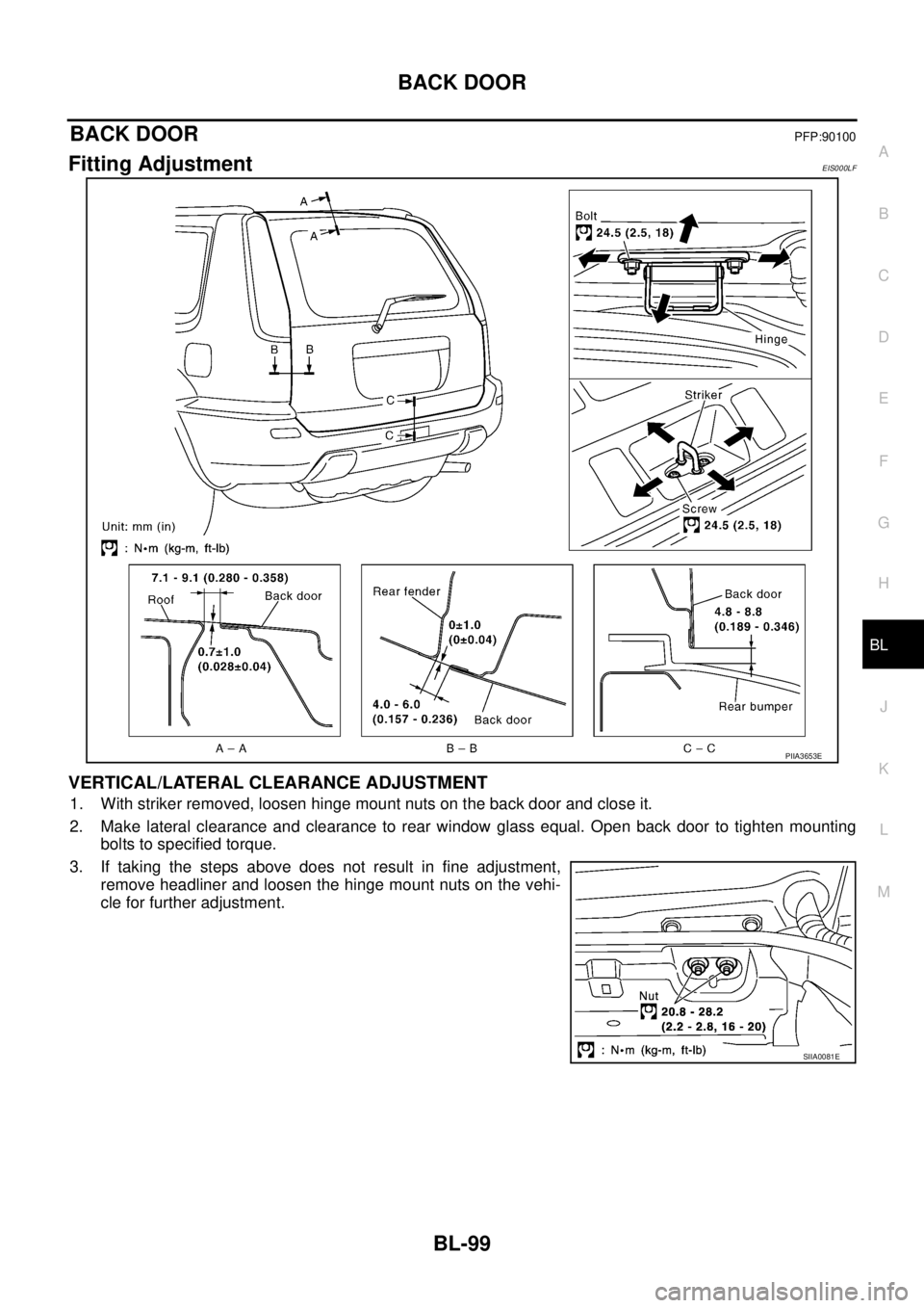
Fitting AdjustmentEIS000LF
VERTICAL/LATERAL CLEARANCE ADJUSTMENT
1. With striker removed, loosen hinge mount nuts on the back door and close it.
2. Make lateral clearance and clearance to rear window glass equal. Open back door to tighten mounting
bolts to specified torque.
3. If taking the steps above does not result in fine adjustment,
remove headliner and loosen the hinge mount nuts on the vehi-
cle for further adjustment.
PIIA3653E
SIIA0081E
Page 3715 of 4555
GW-1
GLASSES, WINDOW SYSTEM & MIRRORS
I BODY
CONTENTS
C
D
E
F
G
H
J
K
L
M
SECTION GW
A
B
GW
GLASSES, WINDOW SYSTEM & MIRRORS
PRECAUTIONS .......................................................... 3
Precautions for Supplemental Restraint System
(SRS) “AIR BAG” and “SEAT BELT PRE-TEN-
SIONER” .................................................................. 3
Precautions .............................................................. 3
PREPARATION ........................................................... 4
Commercial Service Tools ........................................ 4
SQUEAK AND RATTLE TROUBLE DIAGNOSES ..... 5
Work Flow ................................................................ 5
CUSTOMER INTERVIEW ..................................... 5
DUPLICATE THE NOISE AND TEST DRIVE ....... 6
CHECK RELATED SERVICE BULLETINS ........... 6
LOCATE THE NOISE AND IDENTIFY THE
ROOT CAUSE ...................................................... 6
REPAIR THE CAUSE ........................................... 6
CONFIRM THE REPAIR ....................................... 7
Generic Squeak and Rattle Troubleshooting ........... 7
INSTRUMENT PANEL .......................................... 7
CENTER CONSOLE ............................................. 7
DOORS ................................................................. 7
TRUNK .................................................................. 8
SUNROOF/HEADLINING ..................................... 8
SEATS ................................................................... 8
UNDERHOOD ....................................................... 8
Diagnostic Worksheet .............................................. 9
WINDSHIELD GLASS AND MOLDING ....................11
Removal and Installation ......................................... 11
REMOVAL ............................................................ 11
INSTALLATION ................................................... 12
SIDE WINDOW GLASS ............................................ 13
Removal and Installation ........................................ 13
REMOVAL ........................................................... 13
INSTALLATION ................................................... 13
REPAIRING WATER LEAKS .............................. 14
BACK DOOR WINDOW GLASS .............................. 15
Removal and Installation ........................................ 15
REMOVAL ........................................................... 15
INSTALLATION ................................................... 16
REAR WINDOW DEFOGGER .................................. 17
Component Parts and Harness Connector Location ... 17System Description / LHD Models .......................... 17
System Description / RHD Models ......................... 18
Wiring Diagram — DEF — / For LHD models ........ 19
Wiring Diagram — DEF — / For RHD models ........ 21
Terminals and Reference Value for Time Control
Unit (RHD models) ................................................. 23
Trouble Diagnoses ................................................. 23
Rear Window Defogger Relay Power Supply Check
1 .............................................................................. 24
Time Control Unit Power Supply and Ground Check ... 25
Rear Window Defogger Switch Circuit Check ........ 26
Rear Window Defogger Relay Power Supply Check
2 .............................................................................. 28
Rear Window Defogger Circuit Check 1 ................. 30
Rear Window Defogger Circuit Check 2 ................. 31
Door Mirror Defogger Circuit Check ....................... 32
Rear Window Defogger Indicator Lamp Check 1 ... 34
Rear Window Defogger Indicator Lamp Check 2 ... 36
Filament Check ....................................................... 38
Filament Repair ...................................................... 38
REPAIR EQUIPMENT ......................................... 38
REPAIRING PROCEDURE ................................. 39
POWER WINDOW SYSTEM .................................... 40
Component Parts and Harness Connector Location ... 40
System Description ................................................. 40
MANUAL OPERATION ........................................ 41
AUTO OPERATION ............................................. 44
POWER WINDOW LOCK ................................... 44
TIMER FUNCTION .............................................. 44
DRIVER WINDOW ANTI–PINCH FUNCTION .... 44
Schematic / For LHD models .................................. 45
Wiring Diagram – WINDOW – / For LHD models ... 46
Terminal and Reference Value for Power Window
Main Switch / For LHD models ............................... 50
Schematic / For RHD models ................................. 52
Wiring Diagram – WINDOW – / For RHD models ... 53
Terminal and Reference Value for Power Window
Main Switch / For RHD models .............................. 57
Trouble Diagnoses Symptom Chart ....................... 58
Power Window Relay Power Supply and Ground
Page 3716 of 4555

GW-2 Circuit Check .......................................................... 59
Power Window Main Switch Power Supply and
Ground Circuit Check ............................................. 60
Power Window Motor (Driver side) Circuit Check ... 61
Power Window Motor Circuit Check ....................... 62
Power Window Switch Check ................................. 63
Power Window (Passenger side) Circuit Check ..... 64
Power Window (Rear LH) Circuit Check ................. 66
Power Window (Rear RH) Circuit Check ................ 68
Limit Switch Circuit Check ...................................... 70
Encoder Circuit Check ............................................ 72
Door Switch Check ................................................. 77
FRONT DOOR GLASS AND REGULATOR ............. 80
Removal and Installation ........................................ 80
REMOVAL ........................................................... 80
INSTALLATION .................................................... 81
INSPECTION AFTER REMOVAL ........................ 81
INSPECTION AFTER INSTALLATION ................ 81
FITTING INSPECTION ........................................ 82REAR DOOR GLASS AND REGULATOR ............... 83
Removal and Installation ......................................... 83
REMOVAL ............................................................ 83
INSTALLATION .................................................... 85
INSPECTION AFTER REMOVAL ........................ 85
FITTING INSPECTION ........................................ 85
DOOR MIRROR ......................................................... 86
Precautions to Handle Retractable Power Door Mir-
rors .......................................................................... 86
Wiring Diagram — MIRROR — / For LHD Models ... 87
Wiring Diagram — MIRROR — / For RHD Models ... 89
Removal and Installation ......................................... 91
REMOVAL ............................................................ 91
INSTALLATION .................................................... 91
Disassembly and Assembly .................................... 92
DISASSEMBLY .................................................... 92
ASSEMBLY .......................................................... 93
INSIDE MIRROR ....................................................... 94
Removal and Installation ......................................... 94
REMOVAL ............................................................ 94
INSTALLATION .................................................... 94