2005 NISSAN X-TRAIL clock
[x] Cancel search: clockPage 4117 of 4555
ASHTRAY ILLUMINATION
LT-121
C
D
E
F
G
H
I
J
L
MA
B
LT
ASHTRAY ILLUMINATIONPFP:25860
Bulb Replacement, Removal and InstallationEKS00F86
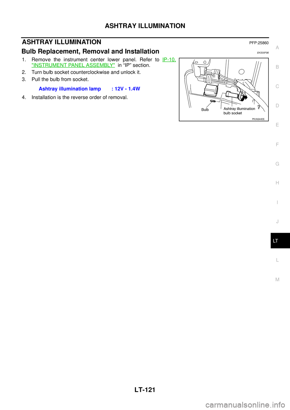
1. Remove the instrument center lower panel. Refer to IP-10,
"INSTRUMENT PANEL ASSEMBLY" in “IP” section.
2. Turn bulb socket counterclockwise and unlock it.
3. Pull the bulb from socket.
4. Installation is the reverse order of removal.Ashtray illumination lamp : 12V - 1.4W
PKIA6440E
Page 4150 of 4555
DI-2 Wiring Diagram — AT/IND —/LHD Models ............ 53
Wiring Diagram — AT/IND —/RHD Models ............ 54
A/T Indicator Does Not Illuminate ........................... 55
WARNING CHIME ..................................................... 56
System Description ................................................. 56
POWER SUPPLY AND GROUND CIRCUIT ....... 56
LIGHT WARNING CHIME ................................... 56
SEAT BELT WARNING CHIME ........................... 56
KEY REMINDER WARNING CHIME [FOR RHD MODELS] ............................................................. 56
Wiring Diagram — CHIME —/LHD Models ............. 57
Wiring Diagram — CHIME —/RHD Models ............ 58
Symptom Chart ....................................................... 60
Power Supply and Ground Circuit Inspection ......... 60
Front Door Switch (Driver Side) Inspection ............. 61
Lighting Switch Input Signal Inspection .................. 62
CLOCK ...................................................................... 63
Wiring Diagram — CLOCK — ................................. 63
Page 4211 of 4555
CLOCK
DI-63
C
D
E
F
G
H
I
J
L
MA
B
DI
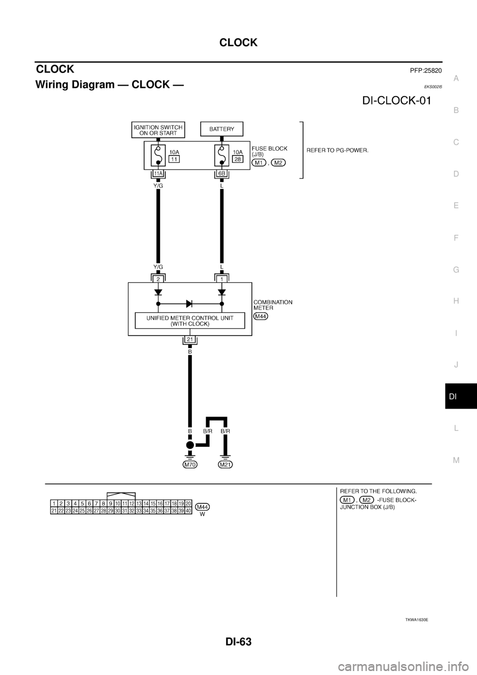
CLOCKPFP:25820
Wiring Diagram — CLOCK —EKS002I5
TKWA1630E
Page 4212 of 4555
DI-64
CLOCK
Page 4481 of 4555
HARNESS
PG-65
C
D
E
F
G
H
I
J
L
MA
B
PG
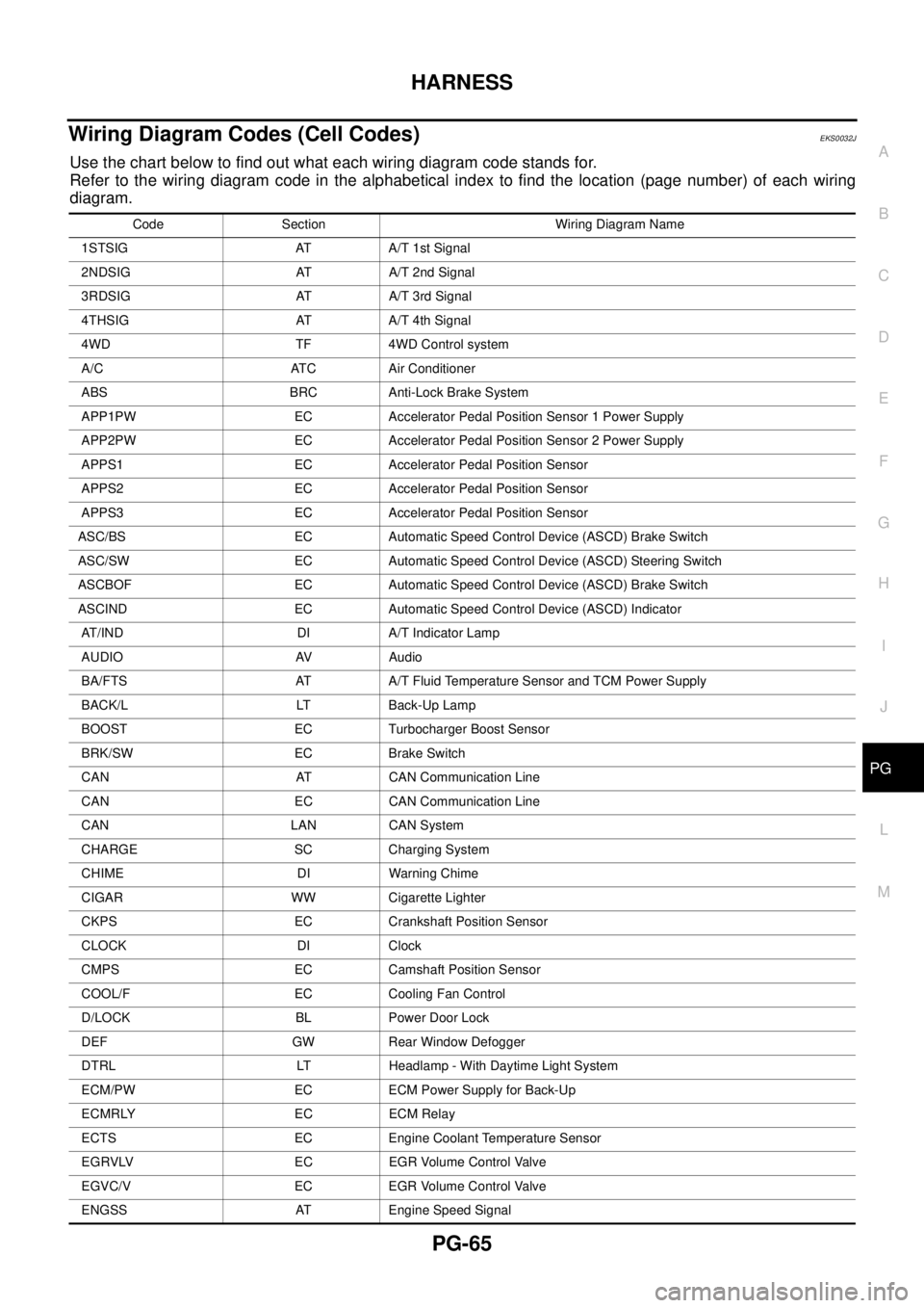
Wiring Diagram Codes (Cell Codes) EKS0032J
Use the chart below to find out what each wiring diagram code stands for.
Refer to the wiring diagram code in the alphabetical index to find the location (page number) of each wiring
diagram.
Code Section Wiring Diagram Name
1STSIG AT A/T 1st Signal
2NDSIG AT A/T 2nd Signal
3RDSIG AT A/T 3rd Signal
4THSIG AT A/T 4th Signal
4WD TF 4WD Control system
A/C ATC Air Conditioner
ABS BRC Anti-Lock Brake System
APP1PW EC Accelerator Pedal Position Sensor 1 Power Supply
APP2PW EC Accelerator Pedal Position Sensor 2 Power Supply
APPS1 EC Accelerator Pedal Position Sensor
APPS2 EC Accelerator Pedal Position Sensor
APPS3 EC Accelerator Pedal Position Sensor
ASC/BS EC Automatic Speed Control Device (ASCD) Brake Switch
ASC/SW EC Automatic Speed Control Device (ASCD) Steering Switch
ASCBOF EC Automatic Speed Control Device (ASCD) Brake Switch
ASCIND EC Automatic Speed Control Device (ASCD) Indicator
AT/IND DI A/T Indicator Lamp
AUDIO AV Audio
BA/FTS AT A/T Fluid Temperature Sensor and TCM Power Supply
BACK/L LT Back-Up Lamp
BOOST EC Turbocharger Boost Sensor
BRK/SW EC Brake Switch
CAN AT CAN Communication Line
CAN EC CAN Communication Line
CAN LAN CAN System
CHARGE SC Charging System
CHIME DI Warning Chime
CIGAR WW Cigarette Lighter
CKPS EC Crankshaft Position Sensor
CLOCK DI Clock
CMPS EC Camshaft Position Sensor
COOL/F EC Cooling Fan Control
D/LOCK BL Power Door Lock
DEF GW Rear Window Defogger
DTRL LT Headlamp - With Daytime Light System
ECM/PW EC ECM Power Supply for Back-Up
ECMRLY EC ECM Relay
ECTS EC Engine Coolant Temperature Sensor
EGRVLV EC EGR Volume Control Valve
EGVC/V EC EGR Volume Control Valve
ENGSS AT Engine Speed Signal
Page 4500 of 4555
MA-4
DESCRIPTION
DESCRIPTIONPFP:00000
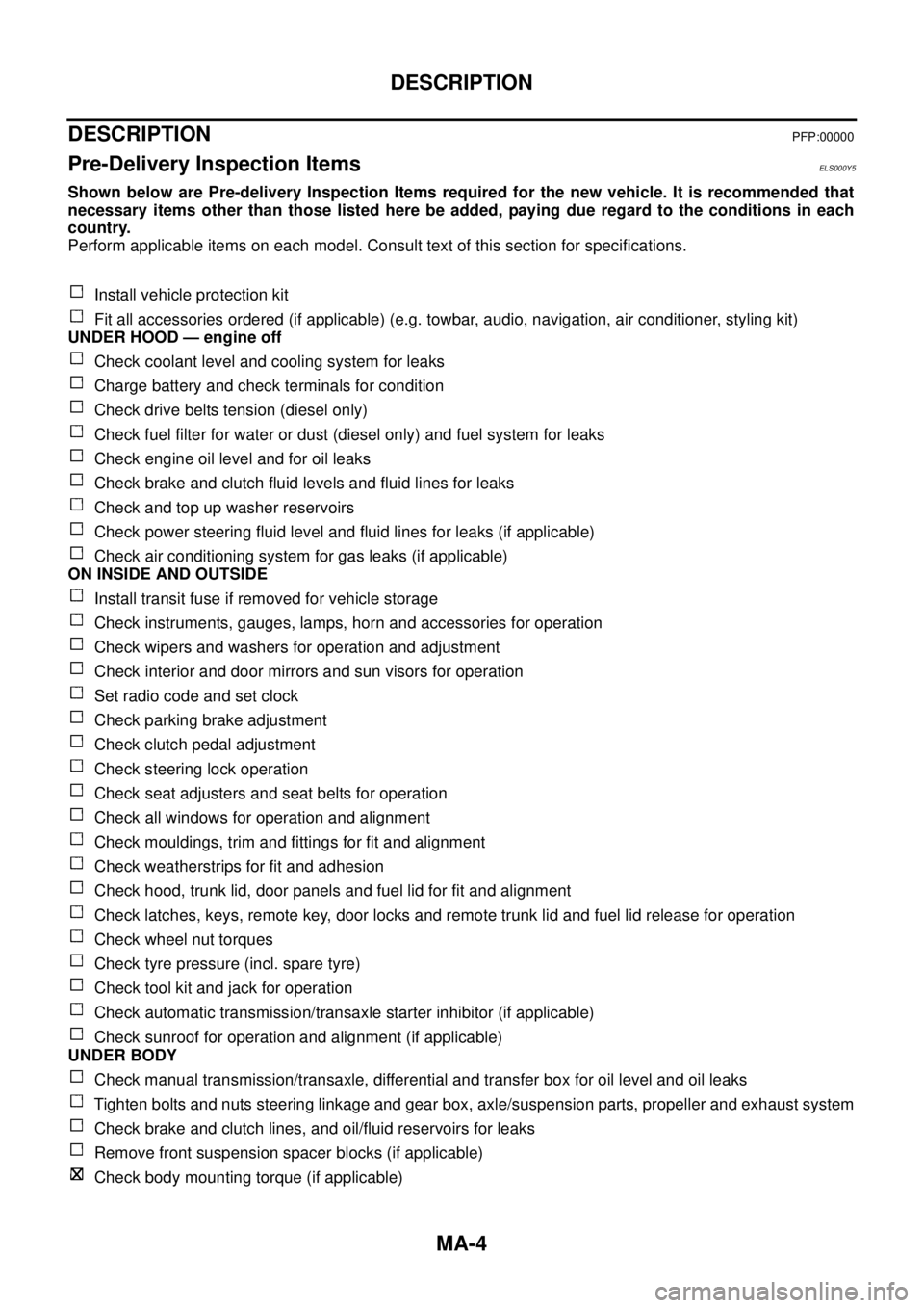
Pre-Delivery Inspection ItemsELS000Y5
Shown below are Pre-delivery Inspection Items required for the new vehicle. It is recommended that
necessary items other than those listed here be added, paying due regard to the conditions in each
country.
Perform applicable items on each model. Consult text of this section for specifications.
Install vehicle protection kit
Fit all accessories ordered (if applicable) (e.g. towbar, audio, navigation, air conditioner, styling kit)
UNDER HOOD — engine off
Check coolant level and cooling system for leaks
Charge battery and check terminals for condition
Check drive belts tension (diesel only)
Check fuel filter for water or dust (diesel only) and fuel system for leaks
Check engine oil level and for oil leaks
Check brake and clutch fluid levels and fluid lines for leaks
Check and top up washer reservoirs
Check power steering fluid level and fluid lines for leaks (if applicable)
Check air conditioning system for gas leaks (if applicable)
ON INSIDE AND OUTSIDE
Install transit fuse if removed for vehicle storage
Check instruments, gauges, lamps, horn and accessories for operation
Check wipers and washers for operation and adjustment
Check interior and door mirrors and sun visors for operation
Set radio code and set clock
Check parking brake adjustment
Check clutch pedal adjustment
Check steering lock operation
Check seat adjusters and seat belts for operation
Check all windows for operation and alignment
Check mouldings, trim and fittings for fit and alignment
Check weatherstrips for fit and adhesion
Check hood, trunk lid, door panels and fuel lid for fit and alignment
Check latches, keys, remote key, door locks and remote trunk lid and fuel lid release for operation
Check wheel nut torques
Check tyre pressure (incl. spare tyre)
Check tool kit and jack for operation
Check automatic transmission/transaxle starter inhibitor (if applicable)
Check sunroof for operation and alignment (if applicable)
UNDER BODY
Check manual transmission/transaxle, differential and transfer box for oil level and oil leaks
Tighten bolts and nuts steering linkage and gear box, axle/suspension parts, propeller and exhaust system
Check brake and clutch lines, and oil/fluid reservoirs for leaks
Remove front suspension spacer blocks (if applicable)
Check body mounting torque (if applicable)
Page 4549 of 4555
IDX-3
A
C
D
E
F
G
H
I
J
K
L B
IDX
ALPHABETICAL INDEX
EC-1641
Basic inspection .. EC-79, EC-578, EC-1012, EC-1382
Battery ................................................................. SC-4
Baulk ring (M/T) .................................... MT-23, MT-41
Blower motor .... ATC-82, ATC-87, ATC-127, MTC-15,
MTC-18
, MTC-24
Blower resistor ................................................ MTC-25
Blower unit ....................... ATC-125, MTC-22, MTC-24
BOOST - Wiring diagram ............... EC-1153, EC-1508
Boring/horning cylinder block(QR20DE-QR25DE) .......
EM-111
Brake booster .................................................... BR-23
Brake fluid change ............................................... BR-8
Brake fluid level ................................................. MA-44
Brake fluid level and line check ........................... BR-8
Brake hydraulic line ........................................... BR-10
Brake inspection ................................................ MA-44
Brake lines and cables inspection ..................... MA-44
Brake master cylinder ........................................ BR-14
Brake pedal ......................................................... BR-6
Brake switch ..... EC-405, EC-809, EC-1313, EC-1664
BRK/SW - Wiring diagram EC-406, EC-811, EC-1314,
EC-1665
Bulb specifications ............................................ LT-152
Bumper, front ....................................................... EI-14
Bumper, rear ........................................................ EI-17
C
Camshaft inspection(QR20DE-QR25DE) .......... EM-58
Camshaft inspection(YD22DDTi) .................... EM-181
Camshaft position sensor (CMPS) EC-1169, EC-1175,
EC-1525
, EC-1531
Camshaft position sensor (PHASE) .. EC-257, EC-701
Camshaft(QR20DE-QR25DE) ........................... EM-56
Camshaft(YD22DDTi) ...................................... EM-180
CAN - Wiring diagram ....... EC-134, EC-634, EC-1057,
EC-1426
, LAN-12, LAN-28, LAN-44, LAN-69, LAN-87,
LAN-105
, LAN-131, LAN-144, LAN-157
CAN (Controller Area Network) ........ LAN-11, LAN-27,
LAN-43
, LAN-68, LAN-86, LAN-104, LAN-130,
LAN-143
, LAN-156
CAN communication EC-39, EC-133, EC-552, EC-633,
EC-989
, EC-1056, EC-1365, EC-1425, AT-32, AT-97,
AT-329
, TF-45, LAN-11, LAN-27, LAN-43, LAN-68,
LAN-86
, LAN-104, LAN-130, LAN-143, LAN-156
Canister-See EVAP canister ............. EC-525, EC-965
CHARGE - Wiring diagram .................... SC-14, SC-15
Charging system ................................................ SC-13
Chassis and body maintenance ........................ MA-39
CHIME - Wiring diagram ................ DI-54, DI-57, DI-58
CIGAR - Wiring diagram .................................. WW-29
Cigarette lighter ............................................... WW-29
Circuit breaker ................................................... PG-12
CKPS - Wiring diagram EC-1059, EC-1158, EC-1164,
EC-1428
, EC-1513, EC-1520
Clearance lamp ................................................ LT-116
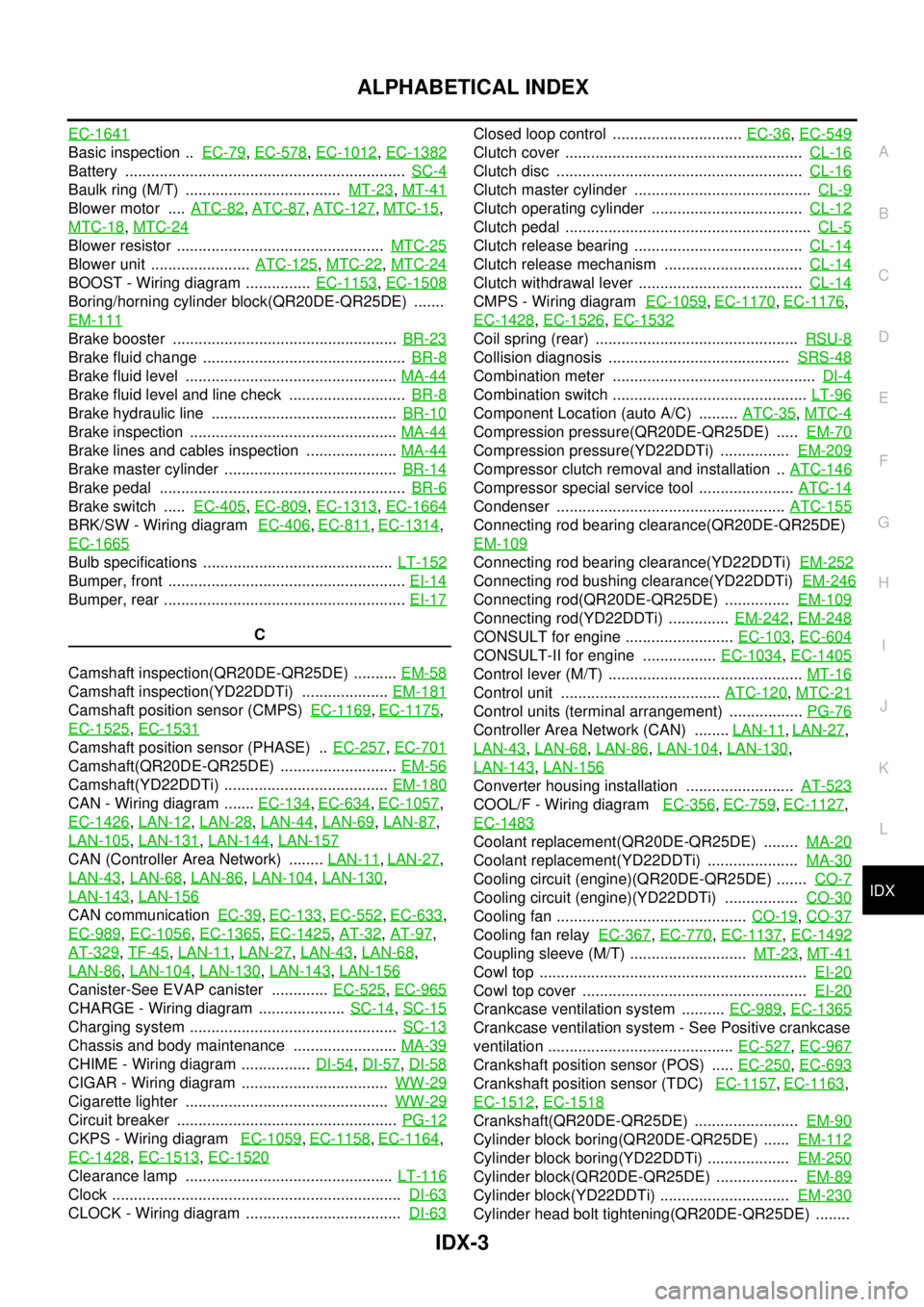
Clock ................................................................... DI-63
CLOCK - Wiring diagram .................................... DI-63
Closed loop control .............................. EC-36, EC-549
Clutch cover ....................................................... CL-16
Clutch disc ......................................................... CL-16
Clutch master cylinder ......................................... CL-9
Clutch operating cylinder ................................... CL-12
Clutch pedal ......................................................... CL-5
Clutch release bearing ....................................... CL-14
Clutch release mechanism ................................ CL-14
Clutch withdrawal lever ...................................... CL-14
CMPS - Wiring diagram EC-1059, EC-1170, EC-1176,
EC-1428
, EC-1526, EC-1532
Coil spring (rear) ............................................... RSU-8
Collision diagnosis .......................................... SRS-48
Combination meter ............................................... DI-4
Combination switch ............................................. LT-96
Component Location (auto A/C) ......... ATC-35, MTC-4
Compression pressure(QR20DE-QR25DE) ..... EM-70
Compression pressure(YD22DDTi) ................ EM-209
Compressor clutch removal and installation .. ATC-146
Compressor special service tool ...................... ATC-14
Condenser ..................................................... ATC-155
Connecting rod bearing clearance(QR20DE-QR25DE)
EM-109
Connecting rod bearing clearance(YD22DDTi) EM-252
Connecting rod bushing clearance(YD22DDTi) EM-246
Connecting rod(QR20DE-QR25DE) ............... EM-109
Connecting rod(YD22DDTi) .............. EM-242, EM-248
CONSULT for engine ......................... EC-103, EC-604
CONSULT-II for engine ................. EC-1034, EC-1405
Control lever (M/T) ............................................. MT-16
Control unit ..................................... ATC-120, MTC-21
Control units (terminal arrangement) ................. PG-76
Controller Area Network (CAN) ........ LAN-11, LAN-27,
LAN-43
, LAN-68, LAN-86, LAN-104, LAN-130,
LAN-143
, LAN-156
Converter housing installation ......................... AT-523
COOL/F - Wiring diagram EC-356, EC-759, EC-1127,
EC-1483
Coolant replacement(QR20DE-QR25DE) ........ MA-20
Coolant replacement(YD22DDTi) ..................... MA-30
Cooling circuit (engine)(QR20DE-QR25DE) ....... CO-7
Cooling circuit (engine)(YD22DDTi) ................. CO-30
Cooling fan ............................................ CO-19, CO-37
Cooling fan relay EC-367, EC-770, EC-1137, EC-1492
Coupling sleeve (M/T) ........................... MT-23, MT-41
Cowl top .............................................................. EI-20
Cowl top cover .................................................... EI-20
Crankcase ventilation system .......... EC-989, EC-1365
Crankcase ventilation system - See Positive crankcase
ventilation ........................................... EC-527
, EC-967
Crankshaft position sensor (POS) ..... EC-250, EC-693
Crankshaft position sensor (TDC) EC-1157, EC-1163,
EC-1512
, EC-1518
Crankshaft(QR20DE-QR25DE) ........................ EM-90
Cylinder block boring(QR20DE-QR25DE) ...... EM-112
Cylinder block boring(YD22DDTi) ................... EM-250
Cylinder block(QR20DE-QR25DE) ................... EM-89
Cylinder block(YD22DDTi) .............................. EM-230
Cylinder head bolt tightening(QR20DE-QR25DE) ........