Page 2290 of 4555
AT-26
OVERALL SYSTEM
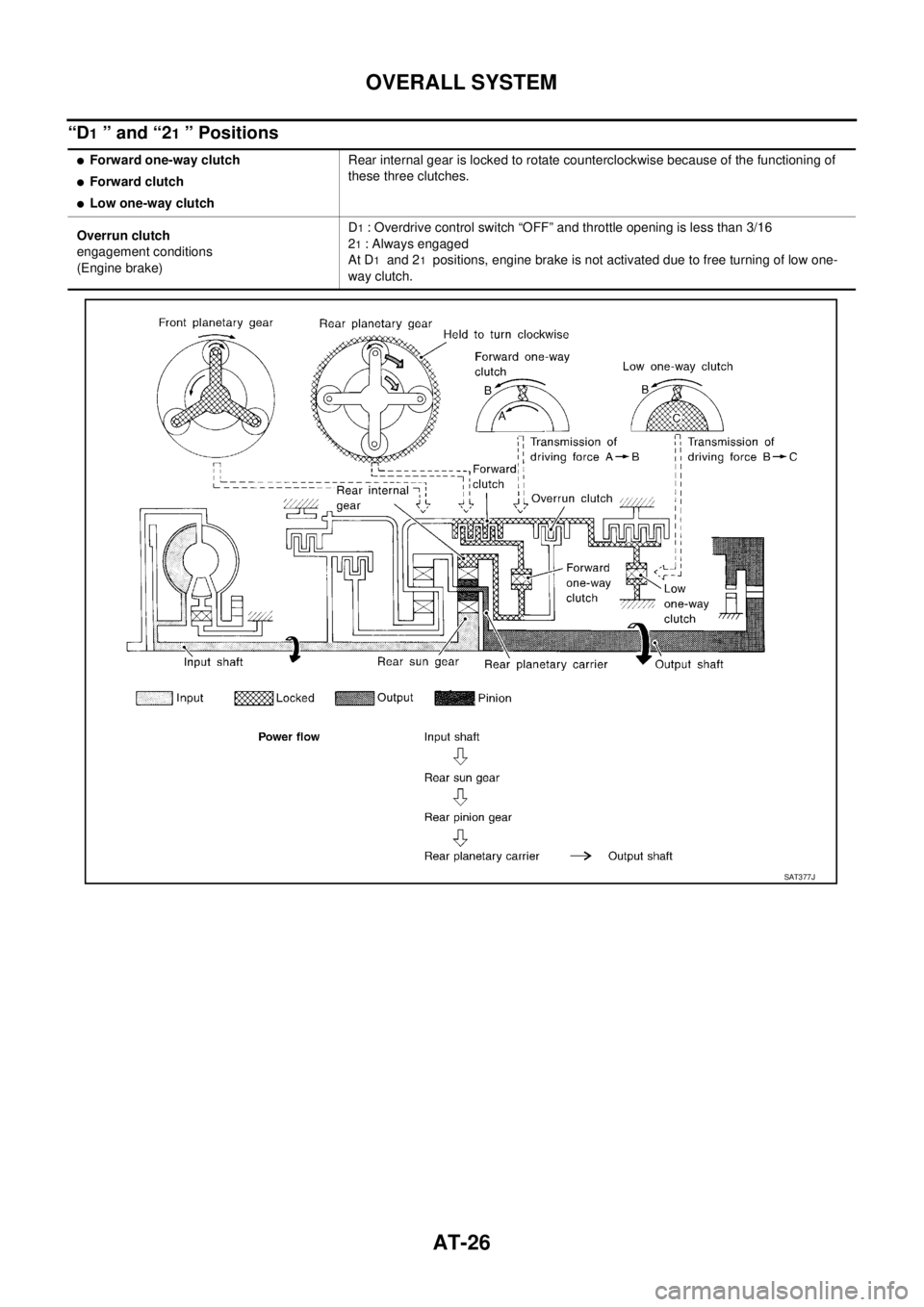
“D1 ” and “21 ” Positions
�Forward one-way clutch
�Forward clutch
�Low one-way clutchRear internal gear is locked to rotate counterclockwise because of the functioning of
these three clutches.
Overrun clutch
engagement conditions
(Engine brake)D
1 : Overdrive control switch “OFF” and throttle opening is less than 3/16
2
1 : Always engaged
At D
1 and 21 positions, engine brake is not activated due to free turning of low one-
way clutch.
SAT377J
Page 2678 of 4555
AT-414
[ALL]
REMOVAL AND INSTALLATION
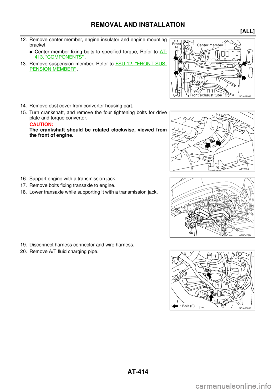
12. Remove center member, engine insulator and engine mounting
bracket.
�Center member fixing bolts to specified torque, Refer to AT-
413, "COMPONENTS" .
13. Remove suspension member. Refer to FSU-12, "
FRONT SUS-
PENSION MEMBER" .
14. Remove dust cover from converter housing part.
15. Turn crankshaft, and remove the four tightening bolts for drive
plate and torque converter.
CAUTION:
The crankshaft should be rotated clockwise, viewed from
the front of engine.
16. Support engine with a transmission jack.
17. Remove bolts fixing transaxle to engine.
18. Lower transaxle while supporting it with a transmission jack.
19. Disconnect harness connector and wire harness.
20. Remove A/T fluid charging pipe.
SCIA0794E
AAT259A
ATM0479D
SCIA5885E
Page 2679 of 4555
![NISSAN X-TRAIL 2005 Service Repair Manual REMOVAL AND INSTALLATION
AT-415
[ALL]
D
E
F
G
H
I
J
K
L
MA
B
AT
21. Remove fluid cooler tube.
INSPECTION
Installation and inspection of torque converter
� After inserting a torque converter to a tra](/manual-img/5/57403/w960_57403-2678.png "NISSAN X-TRAIL 2005 Service Repair Manual REMOVAL AND INSTALLATION
AT-415
[ALL]
D
E
F
G
H
I
J
K
L
MA
B
AT
21. Remove fluid cooler tube.
INSPECTION
Installation and inspection of torque converter
� After inserting a torque converter to a tra")
REMOVAL AND INSTALLATION
AT-415
[ALL]
D
E
F
G
H
I
J
K
L
MA
B
AT
21. Remove fluid cooler tube.
INSPECTION
Installation and inspection of torque converter
� After inserting a torque converter to a transaxle, be sure to
check distance “A” to ensure it is within the reference value limit.
InstallationECS004ND
Install the removed parts in the reverse order of the removal, while paying attention to the following work.
�When installing transaxle to the engine, attach the fixing bolts in
accordance with the following standard.
�Align the positions of tightening bolts for drive plate with those of
the torque converter, and temporarily tighten the bolts. Then,
tighten the bolts to the specified torque. Refer to AT- 4 1 6 , "
Com-
ponents" .
CAUTION:
�When turning crankshaft, turn it clockwise as viewed from
the front of the engine.
�When tightening the tightening bolts for the torque con-
verter after fixing the crankshaft pulley bolts, be sure to
confirm the tightening torque of the crankshaft pulley
mounting bolts.
� After converter is installed to drive plate, rotate crankshaft
several turns and check to be sure that transaxle rotates freely without binding.
�After completing installation, check for fluid leakage, fluid level, and the positions of A/T. Refer to AT- 1 6 ,
"Checking A/T Fluid" , AT- 4 0 9 , "CONTROL CABLE ADJUSTMENT" .
SCIA2596E
Distance “A”
QR20DE models: 19.0 mm (0.75 in) or more
QR25DE models: 14.0 mm (0.55 in) or more
SAT573D
Bolt No.Tightening torque
N·m (kg-m, ft-lb)Bolt length “ L ”
mm (in)
1
75 (7.7, 55)49 (1.93)
2 45 (1.77)
3
43 (4.4, 32)40 (1.57)
4 30 (1.18)
5
36 (3.7, 27)40 (1.57)
6 45 (1.97)
SCIA0795E
SCIA3138E
Page 2688 of 4555
AT-424
[ALL]
DISASSEMBLY
DISASSEMBLYPFP:31020
DisassemblyECS004LZ
1. Drain ATF through drain plug.
2. Remove torque converter.
3. Check torque converter one-way clutch using check tool as
shown in the right figure.
a. Insert check tool into the groove of bearing support built into
one-way clutch outer race.
b. When fixing bearing support with check tool, rotate one- way
clutch spline using screwdriver.
c. Check that inner race rotates clockwise only. If not, replace
torque converter assembly.
SCIA0003E
SAT008D
SAT009D
Page 2698 of 4555
AT-434
[ALL]
DISASSEMBLY
e. Remove front planetary carrier with low & reverse brake piston
and retainer.
f. Remove low and reverse brake spring retainer.
CAUTION:
Do not remove return springs from spring retainer.
g. Check that low one-way clutch rotates in the direction of the
clockwise arrow and locks in the opposite direction.
h. Remove needle bearing, low and reverse brake piston and
retainer from front planetary carrier.
i. Check front planetary carrier, low & reverse brake piston,
retainer and needle bearing for damage or wear.
j. Check front planetary carrier, low one-way clutch and needle
bearing for damage or wear.
k. Check clearance between planetary gears and planetary carrier
with feeler gauge.
Replace front planetary carrier if the clearance exceeds
allowable limit.
SAT023F
SAT148F
SAT048D
SCIA3636E
Standard clearance: 0.20 - 0.70 mm (0.0079 - 0.0276 in)
Allowable limit: 0.80 mm (0.0315 in)
SAT025F
Page 2952 of 4555

INSPECTION AFTER DISASSEMBLY
Check for deformity, cracks and damage of each parts, replace if there are.
Wheel Hub
Check wheel hub for deformation, cracks, and other damage. If")
RAX-8
WHEEL HUB (2WD)
INSPECTION AFTER DISASSEMBLY
Check for deformity, cracks and damage of each parts, replace if there are.
Wheel Hub
Check wheel hub for deformation, cracks, and other damage. If any irregular conditions are found, replace if
there are.
Axle Housing
Inspect axle housing for deformation, cracks, and other damage. If any irregular conditions are found, replace
axle housing.
Snap Ring
Check snap ring for wear or other damage. If any irregular conditions are found, replace snap ring.
ASSEMBLY
1. Using a flat-bladed screwdriver or similar tool, install snap ring securely to the ditch of axle housing inner
side.
2. Using a drift [SST] to press wheel bearing securely from axle
housing inner side as far as it will go.
NOTE:
�Do not reuse wheel bearing.
�Final press load guideline 49,033 N (5,000 kg, 11,000 lb)
3. Using a drift [SST] to press wheel hub onto axle housing.
NOTE:
Final press load guideline 49,033 N (5,000 kg, 11,000 lb).
4. Set sensor rotor to axle housing.
NOTE:
Do not reuse sensor rotor.
5. Install lock nut to axle housing.
6. After installation of lock nut, be sure to perform caulking. Refer
to figure for caulking procedure.
INSPECTION AFTER ASSEMBLY
1. With wheel hub pressed into wheel bearing, apply 49,030 N (5,000 kg, 11,025 lb) to wheel hub and rotate
both clockwise and counterclockwise 10 times to minimize resistance.
2. At a rotating speed of 8 – 12 rpm, place a spring balance at the point where strut is joined (upper side
bolt hole). Measure rotating torque.
SDIA1349E
SDIA0157E
SDIA0964E
Page 3004 of 4555

BR-6
BRAKE PEDAL
BRAKE PEDALPFP:46501
On-Vehicle Inspection and AdjustmentEFS000C1
Adjust clearance between dash panel and brake pedal upper surface
to the following dimensions.
1. Loosen stop lamp switch by rotating it counter-clockwise by 45°.
2. Loosen input rod lock nut (A), then rotate input rod, set pedal to
the specified height, and tighten lock nut (A).
CAUTION:
Confirm threaded end of input rod remains inside the cle-
vis.
3. Pull pedal by hand and hold it. Press stop lamp switch until its
threaded end contacts the stopper rubber.
4. While holding it against the stopper rubber, turn the switch clock-
wise by 45° and secure it.
CAUTION:
Be sure stopper rubber to stop lamp switch screw threaded
end gap (C) is within the specifications.
5. Check pedal free play.
CAUTION:
Be sure stop lamps go off when pedal is released.
6. Start engine and check brake pedal depressed height.
SFIA0348E
H1Brake pedal heightM/T model 156 - 166 mm (6.14 - 6.54 in)
A/T model 164 - 174 mm (6.46 - 6.85 in)
H
2
Pedal height when depressed
[With engine running and at a depression force of 490 N (50 kg,110.6
lb)]M/T model 80 mm (3.15 in) or more
A/T model 85 mm (3.35 in) or more
C Clearance between stopper rubber and threaded end of stop lamp switch 0.74 - 1.96 mm (0.0291 - 0.0772 in)
A Pedal play3 - 11 mm (0.12 - 0.43 in)
: 16 - 21 N·m (1.6 - 2.2 kg-m, 12 - 15 ft-lb)
SFIA0160E
Page 3189 of 4555
. All hoses must include positive shut-")
PRECAUTIONS
ATC-11
C
D
E
F
G
H
I
K
L
MA
B
AT C
SERVICE HOSES
Be certain that the service hoses display the markings described
(colored hose with black stripe). All hoses must include positive shut-
off devices (either manual or automatic) near the end of the hoses
opposite the manifold gauge.
SERVICE COUPLERS
Never attempt to connect HFC-134a (R-134a) service couplers to a
CFC-12 (R-12) A/C system. The HFC-134a (R-134a) couplers will
not properly connect to the CFC-12 (R-12) system. However, if an
improper connection is attempted, discharging and contamination
may occur.
REFRIGERANT WEIGHT SCALE
Verify that no refrigerant other than HFC-134a (R-134a) and speci-
fied lubricants have been used with the scale. If the scale controls
refrigerant flow electronically, the hose fitting must be 1/2″-16
ACME.
CALIBRATING ACR4 WEIGHT SCALE
Calibrate the scale every three months.
To calibrate the weight scale on the ACR4:
1. Press Shift/Reset and Enter at the same time.
2. Press 8787 . “A1 ” will be displayed.
3. Remove all weight from the scale.
4. Press 0 , then press Enter . “0.00 ” will be displayed and change to “A2 ”.
5. Place a known weight (dumbbell or similar weight), between 4.5 and 8.6 kg (10 and 19 lb) on the center of
the weight scale.
6. Enter the known weight using four digits. (Example 10 lb = 10.00, 10.5 lb = 10.50)
7. Press Enter — the display returns to the vacuum mode.
8. Press Shift/Reset and Enter at the same time.
9. Press 6 — the known weight on the scale is displayed.
10. Remove the known weight from the scale. “0.00 ” will be displayed.
11 . P r e s s Shift/Reset to return the ACR4 to the program mode.
RHA272D
Shut-off valve rotation A/C service valve
Clockwise Open
Counterclockwise Close
RHA273D
RHA274D
![NISSAN X-TRAIL 2005 Service Repair Manual AT-424
[ALL]
DISASSEMBLY
DISASSEMBLYPFP:31020
DisassemblyECS004LZ
1. Drain ATF through drain plug.
2. Remove torque converter.
3. Check torque converter one-way clutch using check tool as
shown in t](/manual-img/5/57403/w960_57403-2687.png "NISSAN X-TRAIL 2005 Service Repair Manual AT-424
[ALL]
DISASSEMBLY
DISASSEMBLYPFP:31020
DisassemblyECS004LZ
1. Drain ATF through drain plug.
2. Remove torque converter.
3. Check torque converter one-way clutch using check tool as
shown in t")
![NISSAN X-TRAIL 2005 Service Repair Manual AT-434
[ALL]
DISASSEMBLY
e. Remove front planetary carrier with low & reverse brake piston
and retainer.
f. Remove low and reverse brake spring retainer.
CAUTION:
Do not remove return springs from s](/manual-img/5/57403/w960_57403-2697.png "NISSAN X-TRAIL 2005 Service Repair Manual AT-434
[ALL]
DISASSEMBLY
e. Remove front planetary carrier with low & reverse brake piston
and retainer.
f. Remove low and reverse brake spring retainer.
CAUTION:
Do not remove return springs from s")