Page 2667 of 4555
KEY INTERLOCK CABLE
AT-403
[ALL]
D
E
F
G
H
I
J
K
L
MA
B
AT
2. Remove lock plate from steering lock assembly and remove key
interlock cable.
InstallationECS0040B
1. Turn ignition key to lock position.
2. Set A/T selector lever to P position.
3. Set key interlock cable to steering lock assembly and install lock
plate.
4. Clamp cable to steering column and fix to control cable with
band.
5. Insert interlock rod into adjuster holder.
6. Install casing cap to bracket.
7. Move slider in order to fix adjuster holder to interlock rod.
SAT854J
SAT854J
SAT804E
SAT805E
Page 3091 of 4555
![NISSAN X-TRAIL 2005 Service Repair Manual TROUBLE DIAGNOSIS
BRC-43
[ABS]
C
D
E
G
H
I
J
K
L
MA
B
BRC
OK or NG
OK >> ABS actuator and electric unit (control unit) malfunction. Replace ABS actuator and electric unit
(control unit).
NG >> G sen](/manual-img/5/57403/w960_57403-3090.png "NISSAN X-TRAIL 2005 Service Repair Manual TROUBLE DIAGNOSIS
BRC-43
[ABS]
C
D
E
G
H
I
J
K
L
MA
B
BRC
OK or NG
OK >> ABS actuator and electric unit (control unit) malfunction. Replace ABS actuator and electric unit
(control unit).
NG >> G sen")
TROUBLE DIAGNOSIS
BRC-43
[ABS]
C
D
E
G
H
I
J
K
L
MA
B
BRC
OK or NG
OK >> ABS actuator and electric unit (control unit) malfunction. Replace ABS actuator and electric unit
(control unit).
NG >> G sensor malfunction. Replace G sensor.
Inspection 7: CAN Communication SystemEFS004HI
INSPECTION PROCEDURE
1. CHECK CONNECTOR
1. Turn ignition switch OFF, disconnect the ABS actuator and electric unit (control unit) connector, and check
the terminal for deformation, disconnection, looseness, and so on. If there is a malfunction, repair or
replace the terminal.
2. Reconnect connector to perform self-diagnosis.
Is
“CAN COMM CIRCUIT” displayed in the self-diagnosis display items?
YES >> Print out the self-diagnostic results, and refer to BRC-8, "CAN COMMUNICATION" .
NO >> Connector terminal connector is loose, damaged, open, or shorted.
Symptom 1: ABS Works FrequentlyEFS004HJ
1. CHECK START
Check longitudinal brake force distribution using a brake tester.
OK or NG
OK >> GO TO 2.
NG >> Check brake system.
2. CHECK FRONT AND REAR AXLE
Check to make sure that there is no excessive play in the front and rear axles. Refer to Front: FAX-7, "
On-
Vehicle Inspection" , Rear: RAX-6, "WHEEL BEARING INSPECTION" (2WD), RAX-10, "REAR WHEEL
BEARING" (4WD).
OK or NG
OK >> GO TO 3.
NG >> Repair.
3. CHECK WHEEL SENSOR AND SENSOR ROTOR
Check wheel sensor and sensor rotor for the following.
�Sensor installation for damage
�Sensor rotor installation for damage
�Sensor connector engagement
�Sensor harness
OK or NG
OK >> GO TO 4.
NG >>
�Replace wheel sensor or sensor rotor.
�Repair harness.
4. CHECK ABS WARNING LAMP DISPLAY
Make sure that the warning lamp turns off approximately 1 second after the key switch is turned on or when
driving.
OK or NG
OK >> Normal
NG >> Perform self-diagnosis. Refer to BRC-28, "
SELF-DIAGNOSIS" .
Page 3093 of 4555
![NISSAN X-TRAIL 2005 Service Repair Manual TROUBLE DIAGNOSIS
BRC-45
[ABS]
C
D
E
G
H
I
J
K
L
MA
B
BRC
Symptom 4: ABS Does Not WorkEFS004HM
CAUTION:
ABS does not operate when speed is 10 km/h or lower.
1. CHECK ABS WARNING LAMP DISPLAY
Make su](/manual-img/5/57403/w960_57403-3092.png "NISSAN X-TRAIL 2005 Service Repair Manual TROUBLE DIAGNOSIS
BRC-45
[ABS]
C
D
E
G
H
I
J
K
L
MA
B
BRC
Symptom 4: ABS Does Not WorkEFS004HM
CAUTION:
ABS does not operate when speed is 10 km/h or lower.
1. CHECK ABS WARNING LAMP DISPLAY
Make su")
TROUBLE DIAGNOSIS
BRC-45
[ABS]
C
D
E
G
H
I
J
K
L
MA
B
BRC
Symptom 4: ABS Does Not WorkEFS004HM
CAUTION:
ABS does not operate when speed is 10 km/h or lower.
1. CHECK ABS WARNING LAMP DISPLAY
Make sure that the warning lamp turns off approximately 1 second after the key switch is turned on or when
driving.
OK or NG
OK >> GO TO 3. Check wheel sensor and sensor rotor in BRC-43, "Symptom 1: ABS Works Frequently"
.
NG >> Perform self-diagnosis. Refer to BRC-28, "
SELF-DIAGNOSIS" .
Symptom 5: Pedal Vibration and ABS Operation NoiseEFS004HN
CAUTION:
Under the following conditions, ABS is activated and vibration is felt when brake pedal is lightly
depressed (just place a foot on it). However, this is normal.
�When shifting gears
�When driving on slippery road
�During cornering at high speed
�When passing over bumps or grooves (Approx. 50 mm or more)
�When pulling away just after starting engine (Approx. 10 km/h or more)
1. SYMPTOM CHECK 1
Check if pedal vibration or operation sounds occur when the engine is started.
OK or NG
OK >> GO TO 2.
NG >> Perform self-diagnosis. Refer to BRC-28, "
SELF-DIAGNOSIS" .
2. SYMPTOM CHECK 2
Check symptoms when electrical component (headlamps, etc.) Switches are operated.
Do symptoms occur?
YES >> Check if there is a radio, antenna, antenna lead wire, or wiring close to the control unit. If there is,
move it farther away.
NG >> GO TO 3. Check wheel sensor and sensor rotor in BRC-43, "
Symptom 1: ABS Works Frequently"
.
Page 3161 of 4555
![NISSAN X-TRAIL 2005 Service Repair Manual TROUBLE DIAGNOSIS
BRC-113
[ESP/TCS/ABS]
C
D
E
G
H
I
J
K
L
MA
B
BRC
4. CHECK ABS WARNING LAMP DISPLAY
Make sure that the warning lamp turns off approximately 2 second after the key switch is turned o](/manual-img/5/57403/w960_57403-3160.png "NISSAN X-TRAIL 2005 Service Repair Manual TROUBLE DIAGNOSIS
BRC-113
[ESP/TCS/ABS]
C
D
E
G
H
I
J
K
L
MA
B
BRC
4. CHECK ABS WARNING LAMP DISPLAY
Make sure that the warning lamp turns off approximately 2 second after the key switch is turned o")
TROUBLE DIAGNOSIS
BRC-113
[ESP/TCS/ABS]
C
D
E
G
H
I
J
K
L
MA
B
BRC
4. CHECK ABS WARNING LAMP DISPLAY
Make sure that the warning lamp turns off approximately 2 second after the key switch is turned on or when
driving.
OK or NG
OK >> Normal
NG >> Perform self-diagnosis. Refer to BRC-81, "
SELF-DIAGNOSIS" .
Symptom 2: Unexpected Pedal ReactionEFS005WN
1. CHECK BRAKE PEDAL STROKE
Check brake pedal stroke. Refer to BR-6, "
On-Vehicle Inspection and Adjustment" .
Is the stroke too large?
YES >>�Bleed air from the brake piping. Refer to BR-9, "Bleeding Brake System" .
�Check brake pedal, brake booster, and master cylinder for mount play, looseness, brake sys-
tem fluid leakage, etc. Repair if necessary. Refer to Brake pedal: BR-6, "
BRAKE PEDAL" ,
brake booster and master cylinder: BR-23, "
BRAKE BOOSTER" .
NO >> GO TO 2.
2. PERFORMANCE CHECK
Disconnect ESP/TCS/ABS control unit connector to deactivate ABS. Check if braking force is normal in this
condition. Connect connector after inspection.
OK or NG
OK >> GO TO 3. Wheel Sensor Inspection in Refer to BRC-91, "Inspection 1 Wheel Sensor System" .
NG >> Check brake system.
Symptom 3: Longer Stopping DistanceEFS005WO
CAUTION:
The stopping distance on slippery road surfaces might be longer with the ABS operating than when
the ABS is not operating.
1. PERFORMANCE CHECK
Turn ignition switch OFF. Disconnect ESP/TCS/ABS control unit connector to deactivate ABS. In this condi-
tion, check stopping distance. After inspection, connect connector.
OK or NG
OK >> GO TO BRC-112, "Symptom 1: ABS Works Frequently" .
NG >>
�Bleed air from the brake piping. Refer to BR-9, "Bleeding Brake System" .
�Check brake system.
Symptom 4: ABS Does Not WorkEFS005WP
CAUTION:
ABS does not operate when speed is 10 km/h or lower.
1. CHECK ABS WARNING LAMP DISPLAY
Make sure that the warning lamp turns off approximately 2 second after the key switch is turned on or when
driving.
OK or NG
OK >> GO TO 3. Check wheel sensor and sensor rotor in Refer to BRC-91, "Inspection 1 Wheel Sensor
System" .
NG >> Perform self-diagnosis. Refer to BRC-81, "
SELF-DIAGNOSIS" .
Symptom 5: Pedal Vibration and ABS Operation NoiseEFS005WQ
CAUTION:
Under the following conditions, ABS is activated and vibration is felt when brake pedal is lightly
depressed (just place a foot on it). However, this is normal.
Page 3348 of 4555
 with every NATS
ignition key used. Up to a maximum of 4 NATS ke")
AV-6
AUDIO
Personal Audio Setting
Description
�The radio is designed to store several settings (volume, bass, treble, preset stations) with every NATS
ignition key used. Up to a maximum of 4 NATS keys can be registered. During the communication men-
tioned under “Anti-Theft System”, the radio will recognize the used ignition key and select the accompany-
ing settings.
WITHOUT CASSETTE DECK
Refer to Owner's Manual for audio system operating instructions.
Power is supplied at all times
�through 15A fuse [No. 32, located in the fuse and fusible link box]
�to audio unit terminal 9.
With the ignition switch in the ACC or ON position, power is supplied
�through 10A fuse [No. 4, located in the fuse block (J/B)]
�to audio unit terminal 3.
When audio switch is pushed, audio signals are supplied
�through audio unit terminals 7, 10, 11, 12, 13, 14, 15, and 16
�to terminals 1 and 2 of front door speaker LH and RH
�to terminals 1 and 2 of rear speaker LH and RH
�to terminals 1 and 2 of tweeter LH and RH.
When one of audio steering wheel switches is pushed to volume up, seek up, or source, resistance in steering
switch circuit changes depending on which button is pushed. This will change voltage. Power is supplied
�from audio unit terminal 20
�through combination switch (spiral cable) terminal 4 and 15
�to audio steering wheel switch terminal 1.
Ground is supplied
�from audio steering wheel switch terminal 2
�through combination switch (spiral cable) terminal 17 and 7
�to audio unit terminal 22.
When one of audio steering wheel switches is pushed to volume down, seek down, or special, resistance in
steering switch circuit changes depending on which button is pushed. This will change voltage. Power is sup-
plied
�from audio unit terminal 21
�through combination switch (spiral cable) terminal 5 and 16
�to audio steering wheel switch terminal 3.
Ground is supplied
�from audio steering wheel switch terminal 2
�through combination switch (spiral cable) terminal 17 and 7
�to audio unit terminal 22.
Page 3350 of 4555
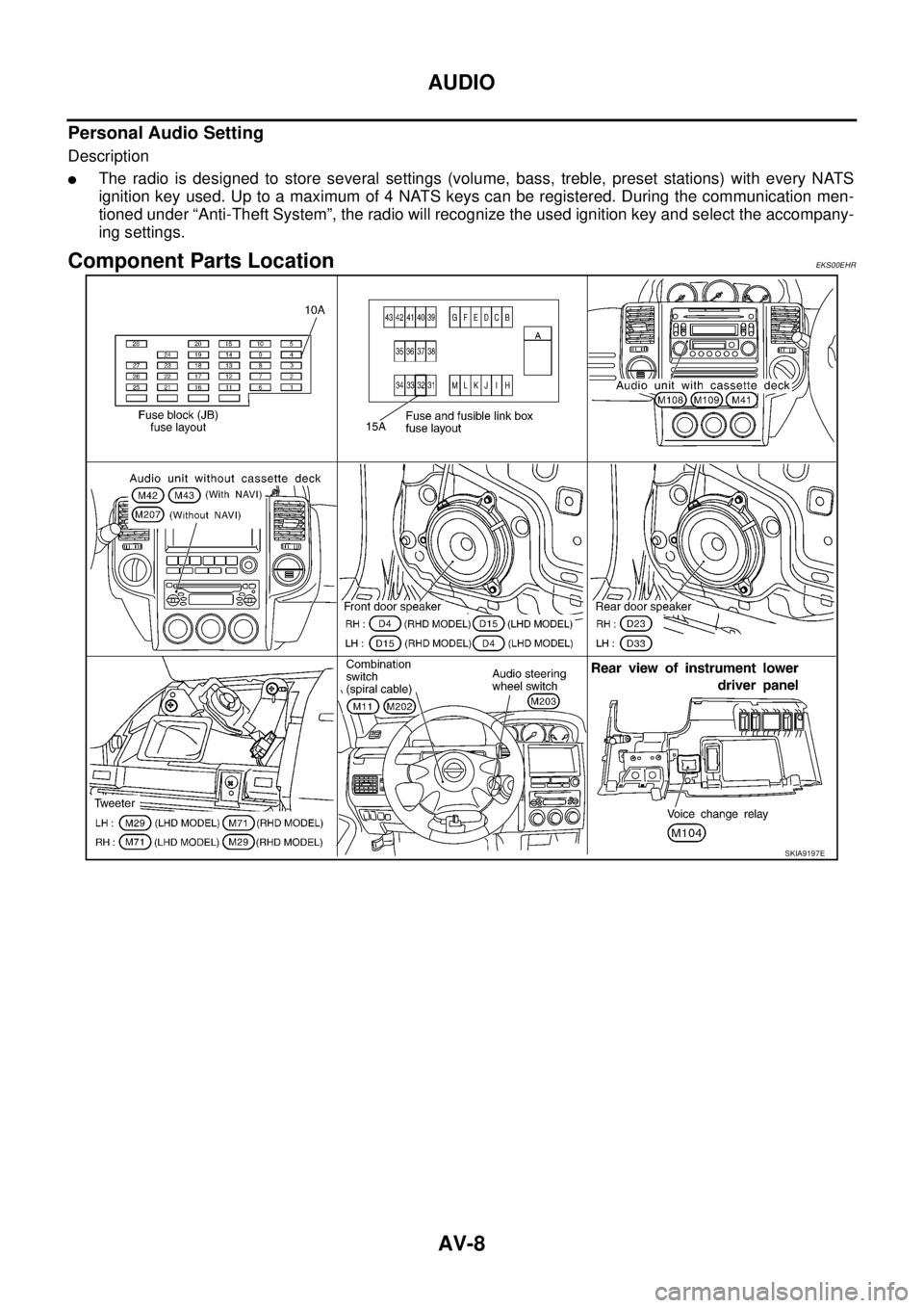
AV-8
AUDIO
Personal Audio Setting
Description
�The radio is designed to store several settings (volume, bass, treble, preset stations) with every NATS
ignition key used. Up to a maximum of 4 NATS keys can be registered. During the communication men-
tioned under “Anti-Theft System”, the radio will recognize the used ignition key and select the accompany-
ing settings.
Component Parts LocationEKS00EHR
SKIA9197E
Page 3388 of 4555
.
�Easy Mode
�Expert Mode
The function of each icon is as follows:
MAP Button
The")
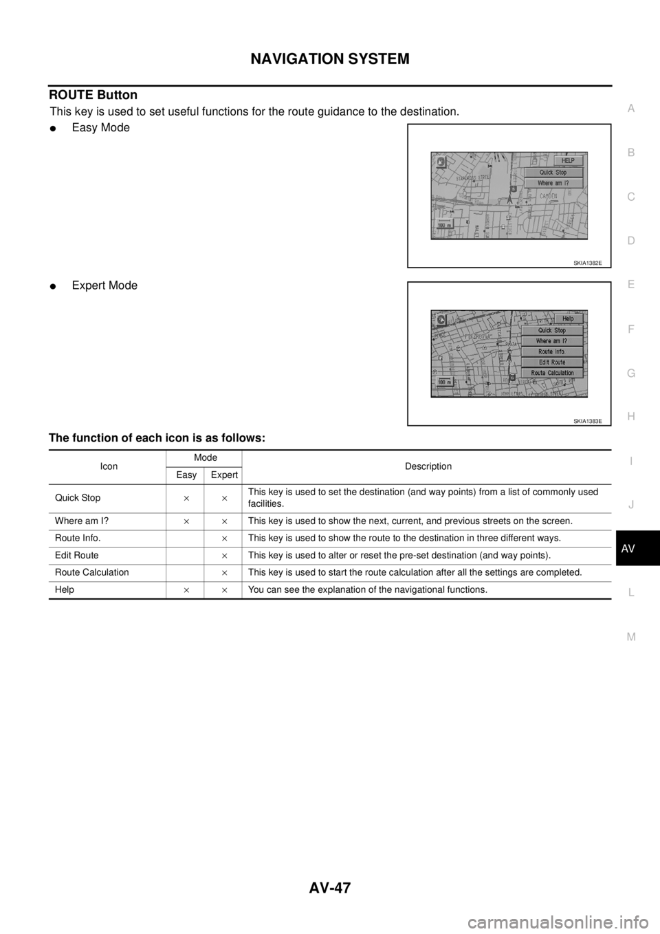
AV-46
NAVIGATION SYSTEM
FUNCTION OF NAVI SWITCH
DEST Button
This key is used to set the destination (and way points).
�Easy Mode
�Expert Mode
The function of each icon is as follows:
MAP Button
The map will be displayed.
SKIA9542E
SKIA9142E
IconMode
Description
Easy Expert
Address Book×Use this category item if you want to go to places stored in the address book.
Address (City / Street)××Use this category item if you know the city name, street name and house number of the
destination (and way points).
Point of Interest (POI)××Use this category item if you want to go to a restaurant, hotel, gas station or other facility.
Phone Number×Use this category item when the destination phone number is known.
Previous Dest.×The ten previous destinations are registered automatically, thereby deleting the older ones.
Intersection×Sets a destination using the intersection of 2 streets.
City Centre×Sets the destination (way point) on the map screen of the area around the input city.
Map×Use this category item if you want to choose the place directly on the map display.
Home×When you set your home in the address book, a route home will be calculated by selecting
this key.
Help××You can see the explanation of the navigational functions.
Page 3389 of 4555
NAVIGATION SYSTEM
AV-47
C
D
E
F
G
H
I
J
L
MA
B
AV
ROUTE Button
This key is used to set useful functions for the route guidance to the destination.
�Easy Mode
�Expert Mode
The function of each icon is as follows:
SKIA1382E
SKIA1383E
IconMode
Description
Easy Expert
Quick Stop××This key is used to set the destination (and way points) from a list of commonly used
facilities.
Where am I?××This key is used to show the next, current, and previous streets on the screen.
Route Info.×This key is used to show the route to the destination in three different ways.
Edit Route×This key is used to alter or reset the pre-set destination (and way points).
Route Calculation×This key is used to start the route calculation after all the settings are completed.
Help××You can see the explanation of the navigational functions.
![NISSAN X-TRAIL 2005 Service Repair Manual KEY INTERLOCK CABLE
AT-403
[ALL]
D
E
F
G
H
I
J
K
L
MA
B
AT
2. Remove lock plate from steering lock assembly and remove key
interlock cable.
InstallationECS0040B
1. Turn ignition key to lock position](/manual-img/5/57403/w960_57403-2666.png "NISSAN X-TRAIL 2005 Service Repair Manual KEY INTERLOCK CABLE
AT-403
[ALL]
D
E
F
G
H
I
J
K
L
MA
B
AT
2. Remove lock plate from steering lock assembly and remove key
interlock cable.
InstallationECS0040B
1. Turn ignition key to lock position")