Page 3753 of 4555

REAR WINDOW DEFOGGER
GW-39
C
D
E
F
G
H
J
K
L
MA
B
GW
REPAIRING PROCEDURE
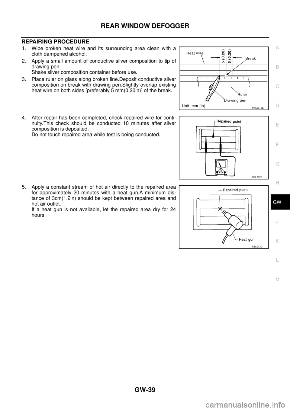
1. Wipe broken heat wire and its surrounding area clean with a
cloth dampened alcohol.
2. Apply a small amount of conductive silver composition to tip of
drawing pen.
Shake silver composition container before use.
3. Place ruler on glass along broken line.Deposit conductive silver
composition on break with drawing pen.Slightly overlap existing
heat wire on both sides [preferably 5 mm(0.20in)] of the break.
4. After repair has been completed, check repaired wire for conti-
nuity.This check should be conducted 10 minutes after silver
composition is deposited.
Do not touch repaired area while test is being conducted.
5. Apply a constant stream of hot air directly to the repaired area
for approximately 20 minutes with a heat gun.A minimum dis-
tance of 3cm(1.2in) should be kept between repaired area and
hot air outlet.
If a heat gun is not available, let the repaired area dry for 24
hours.
PIIA0215E
SEL012D
SEL013D
Page 4092 of 4555

LT-96
LIGHTING AND TURN SIGNAL SWITCH
LIGHTING AND TURN SIGNAL SWITCHPFP:25540
Removal and InstallationEKS0034F
REMOVAL
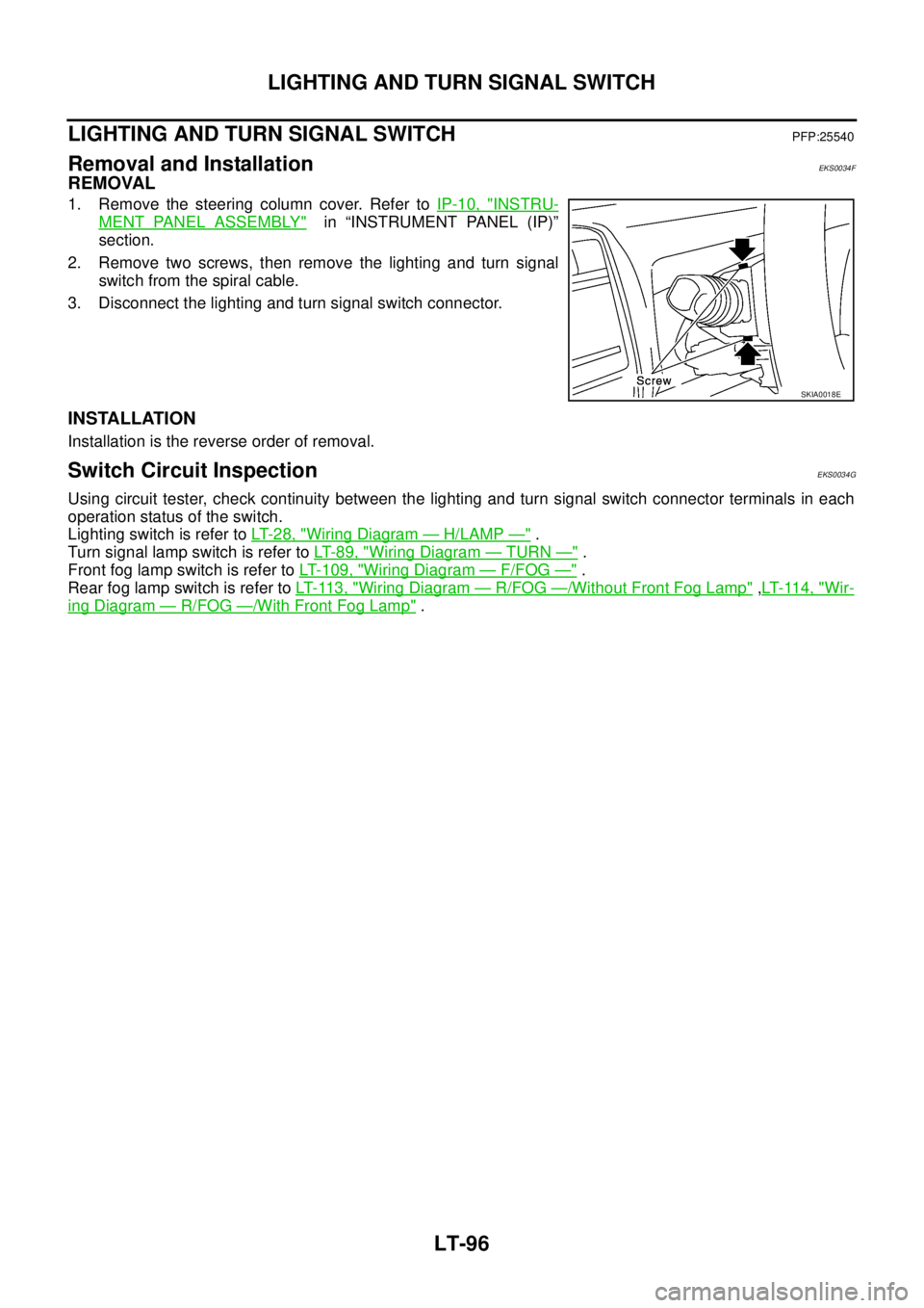
1. Remove the steering column cover. Refer to IP-10, "INSTRU-
MENT PANEL ASSEMBLY" in “INSTRUMENT PANEL (IP)”
section.
2. Remove two screws, then remove the lighting and turn signal
switch from the spiral cable.
3. Disconnect the lighting and turn signal switch connector.
INSTALLATION
Installation is the reverse order of removal.
Switch Circuit InspectionEKS0034G
Using circuit tester, check continuity between the lighting and turn signal switch connector terminals in each
operation status of the switch.
Lighting switch is refer to LT- 2 8 , "
Wiring Diagram — H/LAMP —" .
Turn signal lamp switch is refer to LT- 8 9 , "
Wiring Diagram — TURN —" .
Front fog lamp switch is refer to LT- 1 0 9 , "
Wiring Diagram — F/FOG —" .
Rear fog lamp switch is refer to LT- 11 3 , "
Wiring Diagram — R/FOG —/Without Front Fog Lamp" ,LT- 11 4 , "Wir-
ing Diagram — R/FOG —/With Front Fog Lamp" .
SKIA0018E
Page 4104 of 4555

LT-108
FRONT FOG LAMP
FRONT FOG LAMP PFP:00011
System Description EKS003DF
DESCRIPTION
Power is supplied at all times
�through 10A fuse (No. 31, located in fuse and fusible link box)
�to lighting switch terminal 11,
�through 15A fuse (No. 42, located in fuse and fusible link box)
�to front fog lamp relay terminal 3.
With the lighting switch in the 2ND position, power is supplied
�through lighting switch terminal 12
�to fog lamp switch terminal 32.
FOG LAMP OPERATION
The fog lamp switch is built into the combination switch. The lighting switch must be in the 1ST or 2ND position
for front fog lamp operation.
With the fog lamp switch in the FRONT FOG ON position or FRONT & REAR FOG ON position, power is sup-
plied
�through fog lamp switch terminal 31
�to front fog lamp relay terminal 2.
Ground is supplied
�to front fog lamp relay terminal 1
�through grounds E24 and E50.
The front fog lamp relay is energized and power is supplied
�through front fog lamp relay terminal 5
�to front fog lamp LH and RH terminal 1, and
�to combination meter terminal 15.
Ground is supplied
�to front fog lamp LH and RH terminal 2
�through grounds E24 and E50,
�to combination meter terminal 64
�through grounds M27 and M70.
With power and ground supplied, the front fog lamps and FRONT FOG indicator illuminate.
Page 4108 of 4555

LT-112
REAR FOG LAMP
REAR FOG LAMPPFP:26550
System Description EKS00ESB
DESCRIPTION
Power is supplied at all times (without front fog lamp)
�through 15A fuse (No. 41, located in fuse and fusible link box)
�to lighting switch terminal 5,
�through 10A fuse (No. 36, located in fuse and fusible link box)
�to rear fog lamp relay terminal 3.
Power is supplied at all times (with front fog lamp)
�through 10A fuse (No. 31, located in the fuse and fusible link box)
�to lighting switch terminal 11,
�through 10A fuse (No. 36, located in fuse and fusible link box)
�to rear fog lamp relay terminal 3.
With the lighting switch in the 2ND position, power is supplied (without front fog lamp)
�through lighting switch terminal 25
�to fog lamp switch terminal 34.
With the lighting switch in the 2ND position, power is supplied (with front fog lamp)
�through lighting switch terminal 12
�to fog lamp switch terminal 32.
FOG LAMP OPERATION
The front and rear fog lamp switch is built into the combination switch. The lighting switch must be in the 1ST
or 2ND position for rear fog lamp operation.
With the fog lamp switch in the REAR FOG ON position, ground is supplied
�through fog lamp switch terminal 33
�to rear fog lamp relay terminal 2.
Ground is supplied
�to rear fog lamp relay terminal 1
�through grounds E24 and E50.
The rear fog lamp relay is energized and power is supplied
�through rear fog lamp relay terminal 5
�to rear fog lamp terminal 1, and
�to combination meter terminal 13.
Ground is supplied
�to rear fog lamp terminal 2
�through grounds B8 and B18,
�to combination meter terminal 64
�through grounds M27 and M70.
With power and ground supplied, the rear fog lamps and REAR FOG indicator illuminate.
Page 4118 of 4555

LT-122
ILLUMINATION
ILLUMINATIONPFP:27545
System Description EKS003C7
Power is supplied at all times
�through 10A fuse (No. 31, located in fuse and fusible link box)
�to lighting switch terminal 11.
The lighting switch must be in the 1ST or 2ND position for illumination.
The following chart shows the power and ground connector terminals for the components included in the illu-
mination system.
Component Connector No. Power terminal Ground terminal
Headlamp washier switch M23 4 3
Headlamp aiming switch M24 3 4
ESP off switch M25 3 4
Driving lamp switch M101 1 5
Door mirror remote control switch M26 10 3
Driver pocket lamp M119 1 2
4WD mode switch M39 5 6
Hazard switch M51 7 8
Rear window defogger switch M50 5 6
A/C auto amp. M52 12 11
Combination meter M45 60 63
Heater control panel M55 2 6
Audio unit (with cassette deck) M108 8 case ground
Audio unit (without cassette deck and
with NAVI)M47 1 case ground
Audio unit (without cassette deck and
without NAVI)M207 1 case ground
Cigarette lighter socket M301, M302 3 2
Ashtray illumination M303 5 6
A/T device M58 3 4
NAVI control unit M116, M117 25 1, 4
NAVI switch M113 2 3
Heated seat switch LH (LHD models) B212 5 6
Heated seat switch RH (LHD models) B213 5 6
Page 4481 of 4555

HARNESS
PG-65
C
D
E
F
G
H
I
J
L
MA
B
PG
Wiring Diagram Codes (Cell Codes) EKS0032J
Use the chart below to find out what each wiring diagram code stands for.
Refer to the wiring diagram code in the alphabetical index to find the location (page number) of each wiring
diagram.
Code Section Wiring Diagram Name
1STSIG AT A/T 1st Signal
2NDSIG AT A/T 2nd Signal
3RDSIG AT A/T 3rd Signal
4THSIG AT A/T 4th Signal
4WD TF 4WD Control system
A/C ATC Air Conditioner
ABS BRC Anti-Lock Brake System
APP1PW EC Accelerator Pedal Position Sensor 1 Power Supply
APP2PW EC Accelerator Pedal Position Sensor 2 Power Supply
APPS1 EC Accelerator Pedal Position Sensor
APPS2 EC Accelerator Pedal Position Sensor
APPS3 EC Accelerator Pedal Position Sensor
ASC/BS EC Automatic Speed Control Device (ASCD) Brake Switch
ASC/SW EC Automatic Speed Control Device (ASCD) Steering Switch
ASCBOF EC Automatic Speed Control Device (ASCD) Brake Switch
ASCIND EC Automatic Speed Control Device (ASCD) Indicator
AT/IND DI A/T Indicator Lamp
AUDIO AV Audio
BA/FTS AT A/T Fluid Temperature Sensor and TCM Power Supply
BACK/L LT Back-Up Lamp
BOOST EC Turbocharger Boost Sensor
BRK/SW EC Brake Switch
CAN AT CAN Communication Line
CAN EC CAN Communication Line
CAN LAN CAN System
CHARGE SC Charging System
CHIME DI Warning Chime
CIGAR WW Cigarette Lighter
CKPS EC Crankshaft Position Sensor
CLOCK DI Clock
CMPS EC Camshaft Position Sensor
COOL/F EC Cooling Fan Control
D/LOCK BL Power Door Lock
DEF GW Rear Window Defogger
DTRL LT Headlamp - With Daytime Light System
ECM/PW EC ECM Power Supply for Back-Up
ECMRLY EC ECM Relay
ECTS EC Engine Coolant Temperature Sensor
EGRVLV EC EGR Volume Control Valve
EGVC/V EC EGR Volume Control Valve
ENGSS AT Engine Speed Signal