Page 2168 of 4555

MT-12
M/T OIL
M/T OILPFP:KLD20
Changing M/T OilECS008BR
DRAINING
1. Start engine and let it run to warm up transaxle.
2. Stop engine. Remove drain plug and then drain oil.
3. Set a gasket on drain plug and install it to transaxle case. Tighten drain plug to the specified torque. Refer
to MT-22, "
Case and Housing Components" (RS5F51A) or MT-40, "Case and Housing Components"
(RS6F51A).
CAUTION:
Do not reuse gasket.
FILLING
1. Remove plug (for 2WD models) or filler plug (for 4WD models).
Fill with new oil to transaxle.
2. After refilling oil, check oil level.
3. Set a O-ring on plug (for 2WD models) or gasket on filler plug
(for 4WD models) and then install it to clutch housing.
CAUTION:
Do not reuse O-ring or gasket.
4. Tighten plug mounting bolt (for 2WD models) or filler plug (for 4WD models) to the specified torque. Refer
to MT-22, "
Case and Housing Components" (RS5F51A) or MT-40, "Case and Housing Components"
(RS6F51A).
Checking M/T OilECS008BS
OIL LEAKAGE AND OIL LEVEL
�Make sure that oil is not leaking from transaxle or around it.
�Remove plug (for 2WD models) or filler plug (for 4WD models).
�Measure oil level using a suitable gauge as shown in the figure, and then check if it is within the specifica-
tions.
CAUTION:
Do not start engine while checking oil level.
–For 2WD modelsOil grade and viscosity: Refer to MA-17, "
Fluids and
Lubricants" .
Oil capacity (reference):
Approx. 2.2 (3-7/8 lmp pt)
PCIB1572E
Oil level “L” : 55.0 - 61.0 mm (2.17 - 2.40 in)
PCIB1477E
Page 2170 of 4555
MT-14
SIDE OIL SEAL
SIDE OIL SEALPFP:32113
Removal and InstallationECS008BT
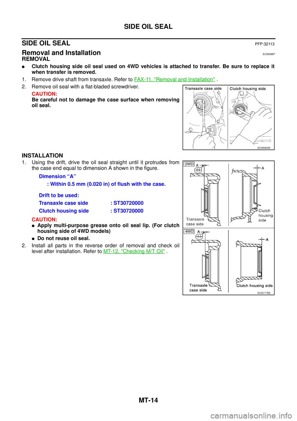
REMOVAL
�Clutch housing side oil seal used on 4WD vehicles is attached to transfer. Be sure to replace it
when transfer is removed.
1. Remove drive shaft from transaxle. Refer to FAX-11, "
Removal and Installation" .
2. Remove oil seal with a flat-bladed screwdriver.
CAUTION:
Be careful not to damage the case surface when removing
oil seal.
INSTALLATION
1. Using the drift, drive the oil seal straight until it protrudes from
the case end equal to dimension A shown in the figure.
CAUTION:
�Apply multi-purpose grease onto oil seal lip. (For clutch
housing side of 4WD models)
�Do not reuse oil seal.
2. Install all parts in the reverse order of removal and check oil
level after installation. Refer to MT-12, "
Checking M/T Oil" .
SCIA0824E
Dimension “A”
: Within 0.5 mm (0.020 in) of flush with the case.
Drift to be used:
Transaxle case side : ST30720000
Clutch housing side : ST30720000
SCIA1776E
Page 2177 of 4555

TRANSAXLE ASSEMBLY
MT-21
D
E
F
G
H
I
J
K
L
MA
B
MT
17. Remove transaxle assembly from the vehicle.
CAUTION:
Secure transaxle assembly to a jack while removing it.
INSTALLATION
Note the following, and install in the reverse order of removal.
�When installing the transaxle assembly to the engine, install the mounting bolts following the standard
below.
CAUTION:
When installing transaxle assembly, be careful not to bring transaxle input shaft into contact with
clutch cover.
–QR engine models
*: Tightening the bolt for 4WD models.
–YD engine models
�After installation, check oil level, and check for leaks and loose
mechanisms. Refer to MT-12, "
Checking M/T Oil" .
MTD0062D
Bolt No. 1 2 3* 4 5 6
Quantity 2 1 1 2 2 2
Bolt length “ ”
mm (in)40
(1.57)75
(2.95)45
(1.77)40
(1.57)30
(1.18)40
(1.57)
Tightening torque
N·m (kg - m, ft- lb)74.5
(7.6, 55)42.7
(4.4, 31)35.3
(3.6, 26)
SCIA0353E
Bolt No. 1 2 3 4 5 6
Quantity 2 2 1 1 3 1
Bolt length “ ”
mm (in)55
(2.17)50
(2.76)120
(4.72)45
(1.77)40
(1.57)35
(1.38)
Tightening torque
N·m (kg - m, ft- lb)44
(4.5, 32)33.5
(3.4, 25)
SCIA0748E
Page 2329 of 4555
TROUBLE DIAGNOSIS — BASIC INSPECTION
AT-65
[EURO-OBD]
D
E
F
G
H
I
J
K
L
MA
B
AT
Stall TestECS004QR
STALL TEST PROCEDURE
1. Check A/T fluid and engine oil levels. If necessary, add.
2. Drive vehicle for approx. 10 minutes or until fluid and oil reach
operating temperature. Refer to AT- 1 6 , "
Checking A/T Fluid" .
3. Set parking brake and block wheels.
4. Install a tachometer where it can be seen by driver during test.
�It is good practice to mark the point of specified engine
rpm on indicator.
5. Start engine, apply foot brake, and place selector lever in D
position.
6. Accelerate to wide open throttle gradually while applying foot
brake.
7. Quickly note the engine stall revolution and immediately release
throttle.
�During test, never hold throttle wide open for more than 5
seconds.
SAT647B
SAT513G
SAT775B
Stall revolution:
QR20DE: 2,450 - 2,950 rpm
QR25DE: 2,300 - 2,750 rpm
SAT514G
Page 2332 of 4555
AT-68
[EURO-OBD]
TROUBLE DIAGNOSIS — BASIC INSPECTION
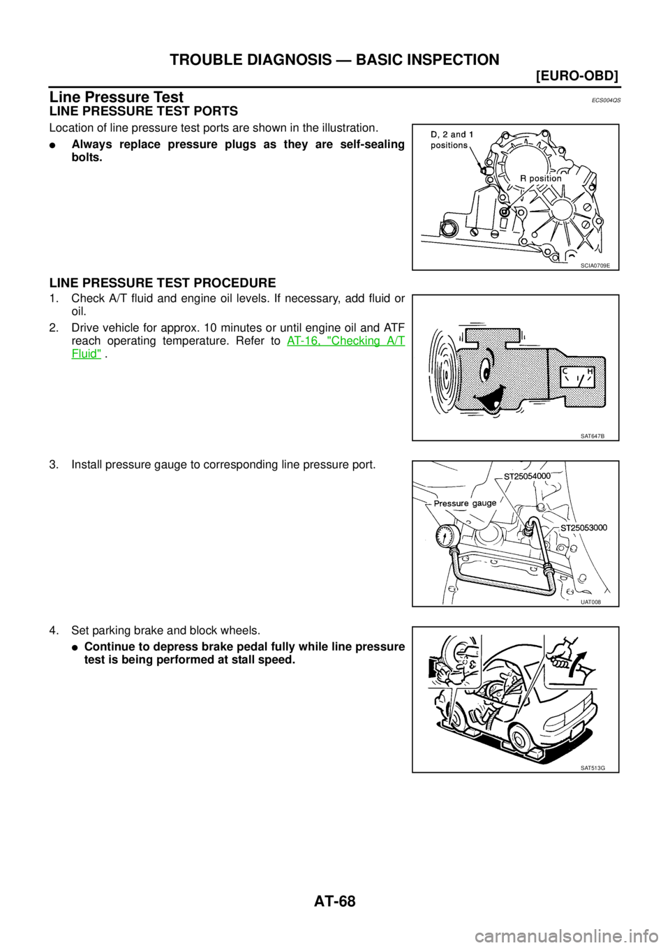
Line Pressure TestECS004QS
LINE PRESSURE TEST PORTS
Location of line pressure test ports are shown in the illustration.
�Always replace pressure plugs as they are self-sealing
bolts.
LINE PRESSURE TEST PROCEDURE
1. Check A/T fluid and engine oil levels. If necessary, add fluid or
oil.
2. Drive vehicle for approx. 10 minutes or until engine oil and ATF
reach operating temperature. Refer to AT- 1 6 , "
Checking A/T
Fluid" .
3. Install pressure gauge to corresponding line pressure port.
4. Set parking brake and block wheels.
�Continue to depress brake pedal fully while line pressure
test is being performed at stall speed.
SCIA0709E
SAT647B
UAT008
SAT513G
Page 2404 of 4555
![NISSAN X-TRAIL 2005 Service Repair Manual AT-140
[EURO-OBD]
DTC P0734 A/T 4TH GEAR FUNCTION
DTC P0734 A/T 4TH GEAR FUNCTIONPFP:31940
DescriptionECS004RM
�This malfunction will not be detected while the O/D OFF indicator lamp is indicating a](/manual-img/5/57403/w960_57403-2403.png "NISSAN X-TRAIL 2005 Service Repair Manual AT-140
[EURO-OBD]
DTC P0734 A/T 4TH GEAR FUNCTION
DTC P0734 A/T 4TH GEAR FUNCTIONPFP:31940
DescriptionECS004RM
�This malfunction will not be detected while the O/D OFF indicator lamp is indicating a")
AT-140
[EURO-OBD]
DTC P0734 A/T 4TH GEAR FUNCTION
DTC P0734 A/T 4TH GEAR FUNCTIONPFP:31940
DescriptionECS004RM
�This malfunction will not be detected while the O/D OFF indicator lamp is indicating another self-diagnosis
malfunction.
�This malfunction is detected when the A/T does not shift into fourth gear position or line pressure is low as
instructed by the TCM. This is not caused by electrical malfunction (circuits open or shorted) but by
mechanical malfunction such as control valve sticking, improper solenoid valve operation, malfunctioning
oil pump or torque converter clutch, etc.
CONSULT-II REFERENCE VALUE IN DATA MONITOR MODE
Remarks: Specification data are reference values.
On Board Diagnosis LogicECS00CU1
This diagnosis monitors actual gear position by checking the torque converter slip ratio calculated by TCM as
follows:
Torque converter slip ratio = A x C/B
A: Output shaft revolution signal from revolution sensor
B: Engine speed signal from ECM
C: Gear ratio determined as gear position which TCM supposes
If the actual gear position is much lower than the position (4th) supposed by TCM, the slip ratio will be much
less than normal. In case the ratio does not reach the specified value, TCM judges this diagnosis malfunction.
This malfunction will be caused when shift solenoid valve A is stuck open or shift solenoid valve B is stuck
closed.
*: P0734 is detected.
And also, this malfunction will be caused when line pressure is lower than normal same as line pressure sole-
noid valve stuck open.
Gear position 1 2 3 4
Shift solenoid valve A ON (Closed) OFF (Open) OFF (Open) ON (Closed)
Shift solenoid valve B ON (Closed) ON (Closed) OFF (Open) OFF (Open)
Monitor item Condition Specification
Line pressure solenoid valve dutySmall throttle opening
(Low line pressure)
↓
Large throttle opening
(High line pressure)Approximately 24%
↓
Approximately 95%
Gear position supposed by TCM 1 2 3 4
In case of gear position with no malfunctions 1 2 34
In case of gear position with shift solenoid valve A stuck open 2 2 33*
In case of gear position with shift solenoid valve B stuck closed 1 2 21*
Diagnostic trouble code Malfunction is detected when... Check items (Possible cause)
: A/T 4TH GR FNCTN
A/T cannot be shifted to the 4th gear posi-
tion even if electrical circuit is good.
�Shift solenoid valve A
�Shift solenoid valve B
�Line pressure solenoid valve
�Each clutch
�Hydraulic control circuit : P0734
Page 2472 of 4555
![NISSAN X-TRAIL 2005 Service Repair Manual AT-208
[EURO-OBD]
TROUBLE DIAGNOSES FOR SYMPTOMS
In “N” Position, Vehicle MovesECS004SX
SYMPTOM:
Vehicle moves forward or backward when selecting “N” position.
1. ADJUST CONTROL CABLE
Check](/manual-img/5/57403/w960_57403-2471.png "NISSAN X-TRAIL 2005 Service Repair Manual AT-208
[EURO-OBD]
TROUBLE DIAGNOSES FOR SYMPTOMS
In “N” Position, Vehicle MovesECS004SX
SYMPTOM:
Vehicle moves forward or backward when selecting “N” position.
1. ADJUST CONTROL CABLE
Check")
AT-208
[EURO-OBD]
TROUBLE DIAGNOSES FOR SYMPTOMS
In “N” Position, Vehicle MovesECS004SX
SYMPTOM:
Vehicle moves forward or backward when selecting “N” position.
1. ADJUST CONTROL CABLE
Check control cable. Refer to AT- 4 0 9 , "
CONTROL CABLE ADJUST-
MENT" .
OK or NG
OK >> GO TO 2.
NG >> Adjust control cable. Refer to AT- 4 0 9 , "
CONTROL
CABLE ADJUSTMENT" .
2. CHECK A/T FLUID LEVEL
Check A/T fluid level. Refer to AT- 1 6 , "
Checking A/T Fluid" .
OK or NG
OK >> GO TO 3.
NG >> Refill ATF.
3. CHECK A/T FLUID CONDITION
1. Remove oil pan. Refer to AT- 4 0 4 , "
COMPONENTS" .
2. Check A/T fluid condition. Refer to AT- 6 4 , "
FLUID CONDITION
CHECK" .
OK or NG
OK >> GO TO 4.
NG >> 1. Disassemble A/T. Refer to AT- 4 2 4 , "
Disassembly" .
2. Check the following items:
–Forward clutch assembly. Refer to AT- 4 7 5 , "Forward
and Overrun Clutches" .
–Overrun clutch assembly. Refer to AT- 4 7 5 , "Forward
and Overrun Clutches" .
–Reverse clutch assembly. Refer to AT- 4 6 4 , "Reverse
Clutch" .
4. CHECK SYMPTOM
Check again. Refer to AT- 7 2 , "
2. CHECK AT IDLE" .
OK or NG
OK >>INSPECTION END
NG >> 1. Perform TCM input/output signal inspection. Refer to AT- 9 4 , "
TCM Terminals and Reference
Va l u e" .
2. If NG, recheck TCM pin terminals for damage or loose connection with harness connector.
SAT023JB
SAT638A
SAT171B
Page 2474 of 4555
![NISSAN X-TRAIL 2005 Service Repair Manual AT-210
[EURO-OBD]
TROUBLE DIAGNOSES FOR SYMPTOMS
Vehicle Does Not Creep Backward In “R” PositionECS004SZ
SYMPTOM:
Vehicle does not creep backward when selecting “R” position.
1. CHECK A/T FL](/manual-img/5/57403/w960_57403-2473.png "NISSAN X-TRAIL 2005 Service Repair Manual AT-210
[EURO-OBD]
TROUBLE DIAGNOSES FOR SYMPTOMS
Vehicle Does Not Creep Backward In “R” PositionECS004SZ
SYMPTOM:
Vehicle does not creep backward when selecting “R” position.
1. CHECK A/T FL")
AT-210
[EURO-OBD]
TROUBLE DIAGNOSES FOR SYMPTOMS
Vehicle Does Not Creep Backward In “R” PositionECS004SZ
SYMPTOM:
Vehicle does not creep backward when selecting “R” position.
1. CHECK A/T FLUID LEVEL
Check A/T fluid level. Refer to AT- 1 6 , "
Checking A/T Fluid" .
OK or NG
OK >> GO TO 2.
NG >> Refill ATF.
2. CHECK LINE PRESSURE
Check line pressure at idle with selector lever in R position. Refer to
AT- 6 8 , "
Line Pressure Test" .
OK or NG
OK >> GO TO 3.
NG >> 1. Remove control valve assembly. Refer to AT- 4 0 4 ,
"Control Valve Assembly and Accumulators" .
2. Check the following items:
–Valves to control line pressure (Pressure regulator
valve, pressure modifier valve, pilot valve and pilot fil-
ter)
–Line pressure solenoid valve
3. Disassemble A/T. Refer to AT- 4 2 4 , "
Disassembly" .
4. Check the following item:
–Oil pump assembly. Refer to AT- 4 4 3 , "Oil Pump" .
3. CHECK STALL TEST
Check stall revolution with selector lever in 1 and R positions.
Refer to AT- 6 5 , "
Stal l Tes t" .
OK or NG
OK >> GO TO 4.
OK in “1” position, NG in R position>>1.Disassemble A/T. Refer to
AT- 4 2 4 , "
Disassembly" .
2. Check the following items:
–Reverse clutch assembly. Refer to AT- 4 6 4 , "Reverse
Clutch" .
–Low & reverse brake assembly. Refer to AT- 4 8 3 , "Low
& Reverse Brake" .
NG in both “1” and “R” positions>>GO TO 6.
SAT638A
SAT494G
SAT493G
![NISSAN X-TRAIL 2005 Service Repair Manual TROUBLE DIAGNOSIS — BASIC INSPECTION
AT-65
[EURO-OBD]
D
E
F
G
H
I
J
K
L
MA
B
AT
Stall TestECS004QR
STALL TEST PROCEDURE
1. Check A/T fluid and engine oil levels. If necessary, add.
2. Drive vehicl](/manual-img/5/57403/w960_57403-2328.png "NISSAN X-TRAIL 2005 Service Repair Manual TROUBLE DIAGNOSIS — BASIC INSPECTION
AT-65
[EURO-OBD]
D
E
F
G
H
I
J
K
L
MA
B
AT
Stall TestECS004QR
STALL TEST PROCEDURE
1. Check A/T fluid and engine oil levels. If necessary, add.
2. Drive vehicl")