Page 2476 of 4555
![NISSAN X-TRAIL 2005 Service Repair Manual AT-212
[EURO-OBD]
TROUBLE DIAGNOSES FOR SYMPTOMS
Vehicle Does Not Creep Forward In “D”, “2” Or “1” PositionECS004T0
SYMPTOM:
Vehicle does not creep forward when selecting “D”, “2� NISSAN X-TRAIL 2005 Service Repair Manual AT-212
[EURO-OBD]
TROUBLE DIAGNOSES FOR SYMPTOMS
Vehicle Does Not Creep Forward In “D”, “2” Or “1” PositionECS004T0
SYMPTOM:
Vehicle does not creep forward when selecting “D”, “2�](/manual-img/5/57403/w960_57403-2475.png)
AT-212
[EURO-OBD]
TROUBLE DIAGNOSES FOR SYMPTOMS
Vehicle Does Not Creep Forward In “D”, “2” Or “1” PositionECS004T0
SYMPTOM:
Vehicle does not creep forward when selecting “D”, “2” or “1” position.
1. CHECK A/T FLUID LEVEL
Check A/T fluid level. Refer to AT- 1 6 , "
Checking A/T Fluid" .
OK or NG
OK >> GO TO 2.
NG >> Refill ATF.
2. CHECK LINE PRESSURE
Check line pressure at idle with selector lever in D position. Refer to
AT- 6 8 , "
Line Pressure Test" .
OK or NG
OK >> GO TO 3.
NG >> 1. Remove control valve assembly. Refer to AT- 4 0 4 ,
"Control Valve Assembly and Accumulators" .
2. Check the following items:
–Valves to control line pressure (Pressure regulator
valve, pressure modifier valve, pilot valve and pilot fil-
ter)
–Line pressure solenoid valve
3. Disassemble A/T. Refer to AT- 4 2 4 , "
Disassembly" .
4. Check the following item:
–Oil pump assembly. Refer to AT- 4 4 3 , "Oil Pump" .
3. CHECK STALL TEST
Check stall revolution with selector lever in D position. Refer to AT-
65, "Stal l Te st" .
OK or NG
OK >> GO TO 4.
NG >> GO TO 6.
SAT638A
SAT494G
SAT493G
Page 2559 of 4555
![NISSAN X-TRAIL 2005 Service Repair Manual TROUBLE DIAGNOSES FOR SYMPTOMS
AT-295
[EXC.F/EURO-OBD]
D
E
F
G
H
I
J
K
L
MA
B
AT
In “N” Position, Vehicle MovesECS00EBH
SYMPTOM:
Vehicle moves forward or backward when selecting “N” position NISSAN X-TRAIL 2005 Service Repair Manual TROUBLE DIAGNOSES FOR SYMPTOMS
AT-295
[EXC.F/EURO-OBD]
D
E
F
G
H
I
J
K
L
MA
B
AT
In “N” Position, Vehicle MovesECS00EBH
SYMPTOM:
Vehicle moves forward or backward when selecting “N” position](/manual-img/5/57403/w960_57403-2558.png)
TROUBLE DIAGNOSES FOR SYMPTOMS
AT-295
[EXC.F/EURO-OBD]
D
E
F
G
H
I
J
K
L
MA
B
AT
In “N” Position, Vehicle MovesECS00EBH
SYMPTOM:
Vehicle moves forward or backward when selecting “N” position.
1. ADJUST CONTROL CABLE
Check control cable. Refer to AT- 4 0 9 , "
CONTROL CABLE ADJUST-
MENT" .
OK or NG
OK >> GO TO 2.
NG >> Adjust control cable. Refer to AT- 4 0 9 , "
CONTROL
CABLE ADJUSTMENT" .
2. CHECK A/T FLUID LEVEL
Check A/T fluid level. Refer to AT- 1 6 , "
Checking A/T Fluid" .
OK or NG
OK >> GO TO 3.
NG >> Refill ATF.
3. CHECK A/T FLUID CONDITION
1. Remove oil pan. Refer to AT- 4 0 4 , "
COMPONENTS" .
2. Check A/T fluid condition. Refer to AT- 2 5 6 , "
FLUID CONDITION
CHECK" .
OK or NG
OK >> GO TO 4.
NG >> 1. Disassemble A/T. Refer to AT- 4 2 4 , "
Disassembly" .
2. Check the following items:
–Forward clutch assembly. Refer to AT- 4 7 5 , "Forward
and Overrun Clutches" .
–Overrun clutch assembly. Refer to AT- 4 7 5 , "Forward
and Overrun Clutches" .
–Reverse clutch assembly. Refer to AT- 4 6 4 , "Reverse
Clutch" .
4. CHECK SYMPTOM
Check again. Refer to AT- 2 6 4 , "
2. CHECK AT IDLE" .
OK or NG
OK >>INSPECTION END
NG >> 1. Perform TCM input/output signal inspection. Refer to AT- 2 8 6 , "
TCM Terminals and Reference
Va l u e" .
2. If NG, recheck TCM pin terminals for damage or loose connection with harness connector.
SAT023JB
SAT638A
SAT171B
Page 2561 of 4555
![NISSAN X-TRAIL 2005 Service Repair Manual TROUBLE DIAGNOSES FOR SYMPTOMS
AT-297
[EXC.F/EURO-OBD]
D
E
F
G
H
I
J
K
L
MA
B
AT
Vehicle Does Not Creep Backward In “R” PositionECS00EBJ
SYMPTOM:
Vehicle does not creep backward when selecting � NISSAN X-TRAIL 2005 Service Repair Manual TROUBLE DIAGNOSES FOR SYMPTOMS
AT-297
[EXC.F/EURO-OBD]
D
E
F
G
H
I
J
K
L
MA
B
AT
Vehicle Does Not Creep Backward In “R” PositionECS00EBJ
SYMPTOM:
Vehicle does not creep backward when selecting �](/manual-img/5/57403/w960_57403-2560.png)
TROUBLE DIAGNOSES FOR SYMPTOMS
AT-297
[EXC.F/EURO-OBD]
D
E
F
G
H
I
J
K
L
MA
B
AT
Vehicle Does Not Creep Backward In “R” PositionECS00EBJ
SYMPTOM:
Vehicle does not creep backward when selecting “R” position.
1. CHECK A/T FLUID LEVEL
Check A/T fluid level. Refer to AT- 1 6 , "
Checking A/T Fluid" .
OK or NG
OK >> GO TO 2.
NG >> Refill ATF.
2. CHECK LINE PRESSURE
Check line pressure at idle with selector lever in R position. Refer to
AT- 2 6 0 , "
Line Pressure Test" .
OK or NG
OK >> GO TO 3.
NG >> 1. Remove control valve assembly. Refer to AT- 4 0 4 ,
"Control Valve Assembly and Accumulators" .
2. Check the following items:
–Valves to control line pressure (Pressure regulator
valve, pressure modifier valve, pilot valve and pilot fil-
ter)
–Line pressure solenoid valve
3. Disassemble A/T. Refer to AT- 4 2 4 , "
Disassembly" .
4. Check the following item:
–Oil pump assembly. Refer to AT- 4 4 3 , "Oil Pump" .
3. CHECK STALL TEST
Check stall revolution with selector lever in 1 and R positions.
Refer to AT- 2 5 7 , "
Stal l Te st" .
OK or NG
OK >> GO TO 4.
OK in “1” position, NG in R position>>1.Disassemble A/T. Refer to
AT- 4 2 4 , "
Disassembly" .
2. Check the following items:
–Reverse clutch assembly. Refer to AT- 4 6 4 , "Reverse
Clutch" .
–Low & reverse brake assembly. Refer to AT- 4 8 3 , "Low
& Reverse Brake" .
NG in both “1” and “R” positions>>GO TO 6.
SAT638A
SAT494G
SAT493G
Page 2563 of 4555
![NISSAN X-TRAIL 2005 Service Repair Manual TROUBLE DIAGNOSES FOR SYMPTOMS
AT-299
[EXC.F/EURO-OBD]
D
E
F
G
H
I
J
K
L
MA
B
AT
Vehicle Does Not Creep Forward In “D”, “2” Or “1” PositionECS00EBK
SYMPTOM:
Vehicle does not creep forwar NISSAN X-TRAIL 2005 Service Repair Manual TROUBLE DIAGNOSES FOR SYMPTOMS
AT-299
[EXC.F/EURO-OBD]
D
E
F
G
H
I
J
K
L
MA
B
AT
Vehicle Does Not Creep Forward In “D”, “2” Or “1” PositionECS00EBK
SYMPTOM:
Vehicle does not creep forwar](/manual-img/5/57403/w960_57403-2562.png)
TROUBLE DIAGNOSES FOR SYMPTOMS
AT-299
[EXC.F/EURO-OBD]
D
E
F
G
H
I
J
K
L
MA
B
AT
Vehicle Does Not Creep Forward In “D”, “2” Or “1” PositionECS00EBK
SYMPTOM:
Vehicle does not creep forward when selecting “D”, “2” or “1” position.
1. CHECK A/T FLUID LEVEL
Check A/T fluid level. Refer to AT- 1 6 , "
Checking A/T Fluid" .
OK or NG
OK >> GO TO 2.
NG >> Refill ATF.
2. CHECK LINE PRESSURE
Check line pressure at idle with selector lever in D position. Refer to
AT- 2 6 0 , "
Line Pressure Test" .
OK or NG
OK >> GO TO 3.
NG >> 1. Remove control valve assembly. Refer to AT- 4 0 4 ,
"Control Valve Assembly and Accumulators" .
2. Check the following items:
–Valves to control line pressure (Pressure regulator
valve, pressure modifier valve, pilot valve and pilot fil-
ter)
–Line pressure solenoid valve
3. Disassemble A/T. Refer to AT- 4 2 4 , "
Disassembly" .
4. Check the following item:
–Oil pump assembly. Refer to AT- 4 4 3 , "Oil Pump" .
3. CHECK STALL TEST
Check stall revolution with selector lever in D position. Refer to AT-
257, "Stall Test" .
OK or NG
OK >> GO TO 4.
NG >> GO TO 6.
SAT638A
SAT494G
SAT493G
Page 2671 of 4555
![NISSAN X-TRAIL 2005 Service Repair Manual ON-VEHICLE SERVICE
AT-407
[ALL]
D
E
F
G
H
I
J
K
L
MA
B
AT
11. Blow air into the oil hole as shown in the figure and remove
servo release accumulator piston from transaxle case.
CAUTION:
�Strong flow NISSAN X-TRAIL 2005 Service Repair Manual ON-VEHICLE SERVICE
AT-407
[ALL]
D
E
F
G
H
I
J
K
L
MA
B
AT
11. Blow air into the oil hole as shown in the figure and remove
servo release accumulator piston from transaxle case.
CAUTION:
�Strong flow](/manual-img/5/57403/w960_57403-2670.png)
ON-VEHICLE SERVICE
AT-407
[ALL]
D
E
F
G
H
I
J
K
L
MA
B
AT
11. Blow air into the oil hole as shown in the figure and remove
servo release accumulator piston from transaxle case.
CAUTION:
�Strong flow of air will push the accumulator piston out
along with a splash of oil. Cover the area with paper tow-
els and blow air little by little to avoid this.
�Wrap the removed accumulator piston in a paper towel.
12. Remove O-ring from servo release accumulator piston.
13. Blow air into the oil hole shown in the figure and remove N-D
accumulator piston and return spring from transaxle case.
CAUTION:
�Strong flow of air will push the accumulator piston out
along with a splash of oil. Cover the area with paper tow-
els and blow air little by little to avoid this.
�Wrap the removed accumulator piston in a paper towel.
14. Remove O-ring from N-D accumulator piston.
15. Remove lip seals from oil groove for band servo.
INSTALLATION
�Note the following, and install in the reverse order of removal.
�Set manual shaft in Neutral position, then align manual
plate with groove in manual valve.
�After installing control valve assembly to transaxle case,
make sure that selector lever can be moved to all positions.
�After completing installation, check for leakage, and fluid
level. Refer to AT- 1 6 , "
Checking A/T Fluid".
CAUTION:
�Do not reuse O-ring and lip seal.
�Do not reuse oil pan gasket and oil pan fixing bolt.
SAT019DA
SAT020D
SAT497H
Page 2814 of 4555

TF-10
TRANSFER OIL
TRANSFER OILPFP:KLD30
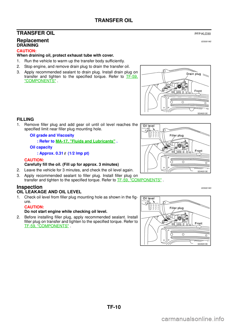
ReplacementEDS001W2
DRAINING
CAUTION:
When draining oil, protect exhaust tube with cover.
1. Run the vehicle to warm up the transfer body sufficiently.
2. Stop engine, and remove drain plug to drain the transfer oil.
3. Apply recommended sealant to drain plug. Install drain plug on
transfer and tighten to the specified torque. Refer to TF-59,
"COMPONENTS" .
FILLING
1. Remove filler plug and add gear oil until oil level reaches the
specified limit near filler plug mounting hole.
CAUTION:
Carefully fill the oil. (Fill up for approx. 3 minutes)
2. Leave the vehicle for 3 minutes, and check the oil level again.
3. Apply recommended sealant to filler plug. Install filler plug on
transfer and tighten to the specified torque. Refer to TF-59, "
COMPONENTS" .
InspectionEDS001W3
OIL LEAKAGE AND OIL LEVEL
1. Check oil level from filler plug mounting hole as shown in the fig-
ure.
CAUTION:
Do not start engine while checking oil level.
2. Before installing filler plug, apply recommended sealant. Install
filler plug on transfer and tighten to the specified torque. Refer to
TF-59, "
COMPONENTS" .
SDIA0512E
Oil grade and Viscosity
: Refer to MA-17, "
Fluids and Lubricants" .
Oil capacity
: Approx. 0.31 (1/2 lmp pt)
SDIA0513E
SDIA0513E
Page 2875 of 4555

TRANSFER ASSEMBLY
TF-71
C
E
F
G
H
I
J
K
L
MA
B
TF
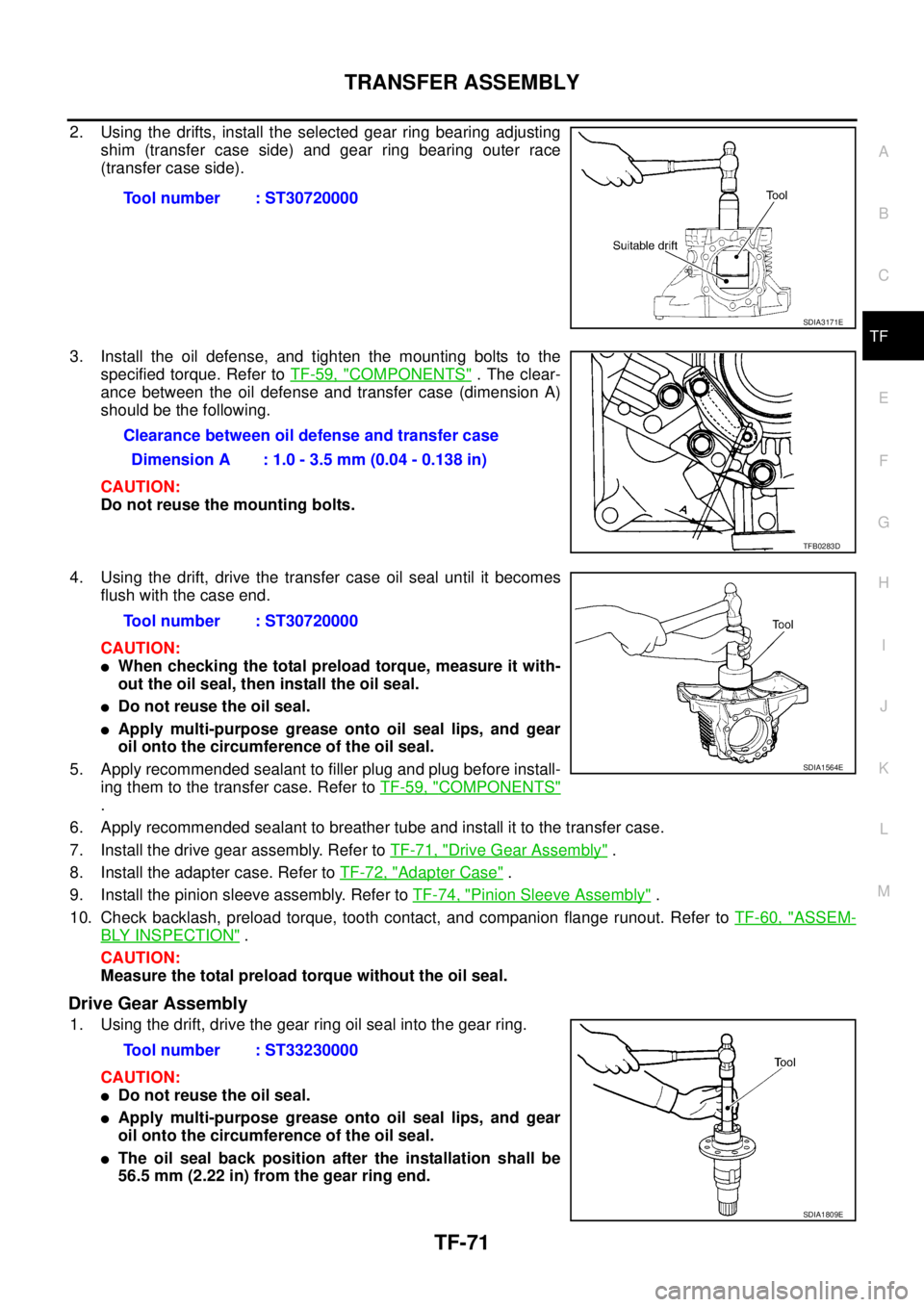
2. Using the drifts, install the selected gear ring bearing adjusting
shim (transfer case side) and gear ring bearing outer race
(transfer case side).
3. Install the oil defense, and tighten the mounting bolts to the
specified torque. Refer to TF-59, "
COMPONENTS" . The clear-
ance between the oil defense and transfer case (dimension A)
should be the following.
CAUTION:
Do not reuse the mounting bolts.
4. Using the drift, drive the transfer case oil seal until it becomes
flush with the case end.
CAUTION:
�When checking the total preload torque, measure it with-
out the oil seal, then install the oil seal.
�Do not reuse the oil seal.
�Apply multi-purpose grease onto oil seal lips, and gear
oil onto the circumference of the oil seal.
5. Apply recommended sealant to filler plug and plug before install-
ing them to the transfer case. Refer to TF-59, "
COMPONENTS"
.
6. Apply recommended sealant to breather tube and install it to the transfer case.
7. Install the drive gear assembly. Refer to TF-71, "
Drive Gear Assembly" .
8. Install the adapter case. Refer to TF-72, "
Adapter Case" .
9. Install the pinion sleeve assembly. Refer to TF-74, "
Pinion Sleeve Assembly" .
10. Check backlash, preload torque, tooth contact, and companion flange runout. Refer to TF-60, "
ASSEM-
BLY INSPECTION" .
CAUTION:
Measure the total preload torque without the oil seal.
Drive Gear Assembly
1. Using the drift, drive the gear ring oil seal into the gear ring.
CAUTION:
�Do not reuse the oil seal.
�Apply multi-purpose grease onto oil seal lips, and gear
oil onto the circumference of the oil seal.
�The oil seal back position after the installation shall be
56.5 mm (2.22 in) from the gear ring end.Tool number : ST30720000
SDIA3171E
Clearance between oil defense and transfer case
Dimension A : 1.0 - 3.5 mm (0.04 - 0.138 in)
TFB0283D
Tool number : ST30720000
SDIA1564E
Tool number : ST33230000
SDIA1809E
Page 2877 of 4555

TRANSFER ASSEMBLY
TF-73
C
E
F
G
H
I
J
K
L
MA
B
TF
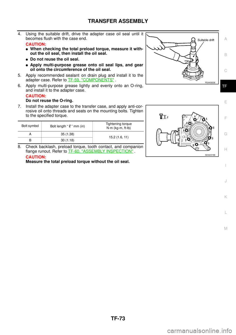
4. Using the suitable drift, drive the adapter case oil seal until it
becomes flush with the case end.
CAUTION:
�When checking the total preload torque, measure it with-
out the oil seal, then install the oil seal.
�Do not reuse the oil seal.
�Apply multi-purpose grease onto oil seal lips, and gear
oil onto the circumference of the oil seal.
5. Apply recommended sealant on drain plug and install it to the
adapter case. Refer to TF-59, "
COMPONENTS" .
6. Apply multi-purpose grease lightly and evenly onto an O-ring,
and install it to the adapter case.
CAUTION:
Do not reuse the O-ring.
7. Install the adapter case to the transfer case, and apply anti-cor-
rosive oil onto threads and seats on the mounting bolts. Tighten
to the specified torque.
8. Check backlash, preload torque, tooth contact, and companion
flange runout. Refer to TF-60, "
ASSEMBLY INSPECTION" .
CAUTION:
Measure the total preload torque without the oil seal.
Bolt symbol
Bolt length “ ” mm (in)Tightening torque
N·m (kg-m, ft-lb)
A 35 (1.38)
15.2 (1.6, 11)
B 30 (1.18)
PDIA0922E
SDIA2318E