Page 208 of 4555
![NISSAN X-TRAIL 2005 Service Repair Manual EM-154
[YD22DDTi]
EXHAUST MANIFOLD AND TURBOCHARGER
INSPECTION AFTER DISASSEMBLY
Surface Distortion
�Check the distortion on the mounting surface in the six directions
using a straightedge and a fee](/manual-img/5/57403/w960_57403-207.png "NISSAN X-TRAIL 2005 Service Repair Manual EM-154
[YD22DDTi]
EXHAUST MANIFOLD AND TURBOCHARGER
INSPECTION AFTER DISASSEMBLY
Surface Distortion
�Check the distortion on the mounting surface in the six directions
using a straightedge and a fee")
EM-154
[YD22DDTi]
EXHAUST MANIFOLD AND TURBOCHARGER
INSPECTION AFTER DISASSEMBLY
Surface Distortion
�Check the distortion on the mounting surface in the six directions
using a straightedge and a feeler gauge.
�If it exceeds the limit, replace exhaust manifold.
TurbochargerEBS00LRJ
CAUTION:
When the compressor wheel turbine, wheel or rotor shaft is damaged, remove all the fragments and
foreign matter left in the following passages in order to prevent a secondary malfunction:
ROTOR SHAFT CLEARANCE
�Make sure that the rotor shaft rotates smoothly without any
resistance when it is rotated by your fingertips.
�Make sure that the rotor shaft is not loose when it is moved ver-
tically or horizontally.
�Measure looseness with a dial indicator inserting its measuring
rod through oil drain hole of turbocharger.
�Replace turbocharger if out of standard.Limit : 0.3 mm (0.012 in)
JEM267G
PBIC2532E
Suction side : Between turbocharger and air cleaner
Exhaust side : Between turbocharger and catalyst
Standard : 0.086 - 0.117 mm (0.0034 - 0.0046 in)
PBIC0727E
Page 210 of 4555
![NISSAN X-TRAIL 2005 Service Repair Manual EM-156
[YD22DDTi]
EXHAUST MANIFOLD AND TURBOCHARGER
TROUBLE DIAGNOSIS OF TURBOCHARGER
Preliminary check:
�Make sure that the engine oil level is between “MIN” and “MAX” of the oil level gaug](/manual-img/5/57403/w960_57403-209.png "NISSAN X-TRAIL 2005 Service Repair Manual EM-156
[YD22DDTi]
EXHAUST MANIFOLD AND TURBOCHARGER
TROUBLE DIAGNOSIS OF TURBOCHARGER
Preliminary check:
�Make sure that the engine oil level is between “MIN” and “MAX” of the oil level gaug")
EM-156
[YD22DDTi]
EXHAUST MANIFOLD AND TURBOCHARGER
TROUBLE DIAGNOSIS OF TURBOCHARGER
Preliminary check:
�Make sure that the engine oil level is between “MIN” and “MAX” of the oil level gauge. (When engine oil
amount is more than “MAX”, engine oil flows into the inlet duct through blow-by gas passage, and turbo-
charger is misjudged malfunction.)
�Ask the customer if he/she always runs the vehicle in idle engine speed to cool the engine oil down after
driving.
�Replace the turbocharger assembly when any malfunction is found after unit inspections specified in the
table below.
�If no malfunction is found after the unit inspections, judge that the turbocharger body has no malfunction.
Check the other parts again.
A: Large possibility
B: Medium possibility
C: Small possibilityInspection item Inspection resultSymptom
(when each inspection item meets each inspection result)
Engine oil
leakageSmoke NoiseInsufficient power/accel-
eration malfunction
Turbine wheelEngine oil leaks C A C C
Carbon is accumulated C A B B
Friction with housing C B A B
Blades are bent or broken — — A A
Compressor wheelInside the air inlet is seriously con-
taminated by engine oil.BB— —
Friction with housing C B A B
Blades are bent or broken — — A A
After checking both turbine and
compressor, inspect rotor shaft
end play.There is resistance when the rotor
shaft is rotated by your fingertips.—CC B
The rotor shaft sometimes does not
rotate by your fingertips.——— A
There is too much play in the bear-
ing.CCB C
Oil return portCarbon or sludge is accumulated in
the waste oil hole.CAC C
Page 215 of 4555
OIL PAN AND OIL STRAINER
EM-161
[YD22DDTi]
C
D
E
F
G
H
I
J
K
L
MA
EM
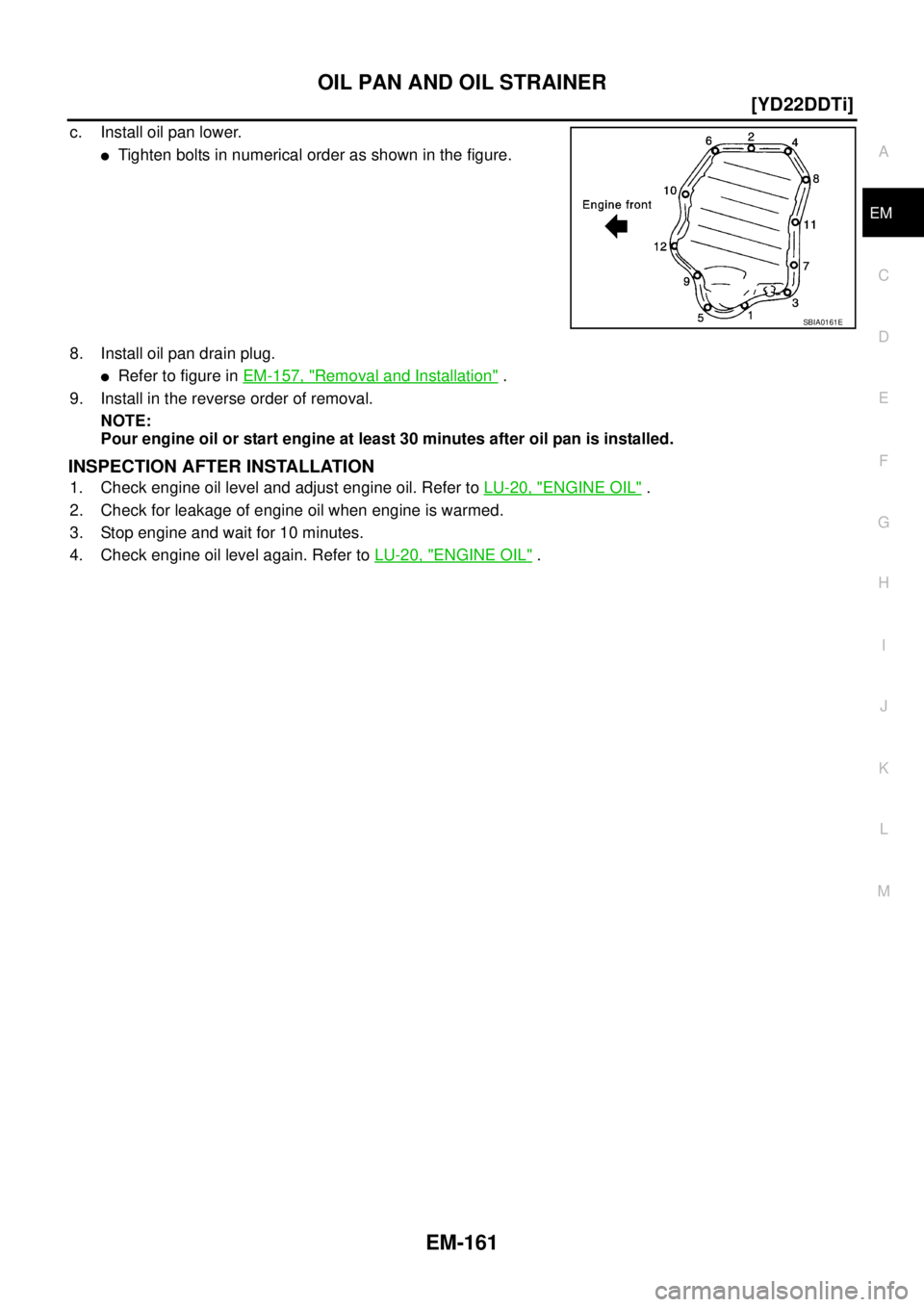
c. Install oil pan lower.
�Tighten bolts in numerical order as shown in the figure.
8. Install oil pan drain plug.
�Refer to figure in EM-157, "Removal and Installation" .
9. Install in the reverse order of removal.
NOTE:
Pour engine oil or start engine at least 30 minutes after oil pan is installed.
INSPECTION AFTER INSTALLATION
1. Check engine oil level and adjust engine oil. Refer to LU-20, "ENGINE OIL" .
2. Check for leakage of engine oil when engine is warmed.
3. Stop engine and wait for 10 minutes.
4. Check engine oil level again. Refer to LU-20, "
ENGINE OIL" .
SBIA0161E
Page 224 of 4555
EM-170
[YD22DDTi]
INJECTION TUBE AND FUEL INJECTOR
CAUTION:
�Check gutter spring in nozzle oil seal on fuel injector for missing.
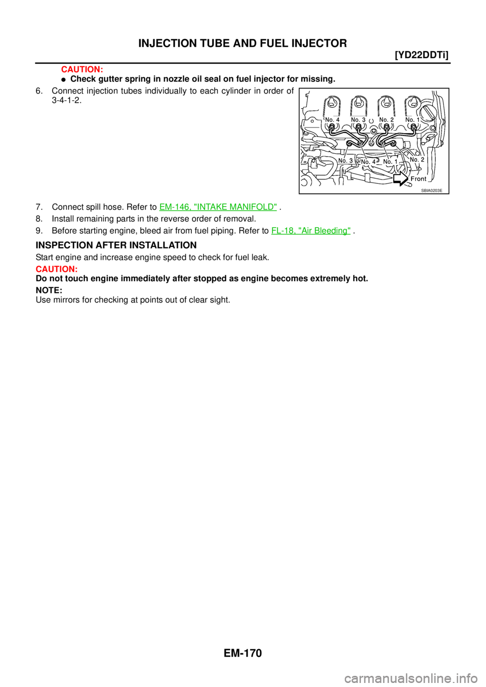
6. Connect injection tubes individually to each cylinder in order of
3-4-1-2.
7. Connect spill hose. Refer to EM-146, "
INTAKE MANIFOLD" .
8. Install remaining parts in the reverse order of removal.
9. Before starting engine, bleed air from fuel piping. Refer to FL-18, "
Air Bleeding" .
INSPECTION AFTER INSTALLATION
Start engine and increase engine speed to check for fuel leak.
CAUTION:
Do not touch engine immediately after stopped as engine becomes extremely hot.
NOTE:
Use mirrors for checking at points out of clear sight.
SBIA0203E
Page 229 of 4555
FUEL PUMP
EM-175
[YD22DDTi]
C
D
E
F
G
H
I
J
K
L
MA
EM
INSPECTION AFTER REMOVAL
Timing Chain
Check for cracks and excessive wear at roller links. Replace
timing chain if necessary.
INSTALLATION
1. Install new oil seal to spacer.
2. Install spacer to fuel pump.
3. Install coupling to fuel pump of spacer.
�Using the TORX wrench (special service tool), tighten the
sprocket nut to fix the coupling.
4. Install adjust shim.
�For shim adjustment, measure dimension “L” [Distance
between front surface of coupling and the fuel pump flange
(spacer)] at two opposing points near the coupling bolt center.
Use the average of these two measurements to select the
shim grade that marked on adjust shim.
�The shim adjustment is required only when the fuel pump is
replaced.
SEM984C
MBIA0045E
MBIA0013E
MBIA0077E
Page 233 of 4555
![NISSAN X-TRAIL 2005 Service Repair Manual ROCKER COVER
EM-179
[YD22DDTi]
C
D
E
F
G
H
I
J
K
L
MA
EM
�Loosen holding bolts in reverse order of that shown in the fig-
ure and remove.
6. Remove rocker cover gasket.
INSTALLATION
1. Apply 3.0 mm](/manual-img/5/57403/w960_57403-232.png "NISSAN X-TRAIL 2005 Service Repair Manual ROCKER COVER
EM-179
[YD22DDTi]
C
D
E
F
G
H
I
J
K
L
MA
EM
�Loosen holding bolts in reverse order of that shown in the fig-
ure and remove.
6. Remove rocker cover gasket.
INSTALLATION
1. Apply 3.0 mm")
ROCKER COVER
EM-179
[YD22DDTi]
C
D
E
F
G
H
I
J
K
L
MA
EM
�Loosen holding bolts in reverse order of that shown in the fig-
ure and remove.
6. Remove rocker cover gasket.
INSTALLATION
1. Apply 3.0 mm (0.118 in) dia. on locations shown in the figure.
�Use Genuine Liquid Gasket or equivalent.
2. Install rocker cover gasket to rocker cover.
3. Tighten holding bolts in numerical order shown in the figure.
Re-tighten to the same torque in the same order as above.
4. Install nozzle oil seal.
�Insert it straight until flange fully contacts rocker cover.
5. Install remaining parts in the reverse order of removal.
6. Before starting engine, bleed air from fuel piping. Refer to FL-18, "
Air Bleeding" .
INSPECTION AFTER INSTALLATION
Start engine and increase engine speed to check for fuel leak.
CAUTION:
Do not touch the engine immediately after stopped as engine becomes extremely hot.
NOTE:
Use mirrors for checking at points out of clear sight.
SBIA0175E
JEM248G
: 7.8 N·m (0.8 kg-m, 69 in-lb)
SBIA0175E
Page 244 of 4555
![NISSAN X-TRAIL 2005 Service Repair Manual EM-190
[YD22DDTi]
OIL SEAL
OIL SEALPFP:12279
Removal and Installation of Valve Oil SealEBS01FBM
REMOVAL
1. Remove camshafts. Refer toEM-180, "Removal and Installation" .
2. Remove adjusting shims an](/manual-img/5/57403/w960_57403-243.png "NISSAN X-TRAIL 2005 Service Repair Manual EM-190
[YD22DDTi]
OIL SEAL
OIL SEALPFP:12279
Removal and Installation of Valve Oil SealEBS01FBM
REMOVAL
1. Remove camshafts. Refer toEM-180, \"Removal and Installation\" .
2. Remove adjusting shims an")
EM-190
[YD22DDTi]
OIL SEAL
OIL SEALPFP:12279
Removal and Installation of Valve Oil SealEBS01FBM
REMOVAL
1. Remove camshafts. Refer toEM-180, "Removal and Installation" .
2. Remove adjusting shims and valve lifters. Refer to EM-180, "
Removal and Installation" .
�Check the installation positions, and keep them to avoid being confused.
3. Rotate crankshaft, and set piston whose valve oil seal is to be removed to TDC. This will prevent valve
from dropping into cylinder.
4. Remove valve collet.
�Compress the valve spring with valve spring compressor,
attachment and adapter (special service tool). Remove valve
collet with a magnet hand.
CAUTION:
When working, be careful not to damage valve lifter holes.
5. Remove valve spring retainer and valve spring.
6. Remove valve oil seal with the valve oil seal puller (special ser-
vice tool).
INSTALLATION
1. Apply new engine oil to valve oil seal joint surface and seal lip.
2. Using the valve oil seal drift (special service tool), install valve oil
seals referring to the dimension shown in the figure.
3. Install in the reverse order of removal.
PBIC2388E
JEM153G
JEM165G
Page 260 of 4555
![NISSAN X-TRAIL 2005 Service Repair Manual EM-206
[YD22DDTi]
PRIMARY TIMING CHAIN
9. Install slack guide.
10. Install chain tensioner.
�Push the plunger of the chain tensioner. While keeping
plunger pressed down with a push pin, etc., instal](/manual-img/5/57403/w960_57403-259.png "NISSAN X-TRAIL 2005 Service Repair Manual EM-206
[YD22DDTi]
PRIMARY TIMING CHAIN
9. Install slack guide.
10. Install chain tensioner.
�Push the plunger of the chain tensioner. While keeping
plunger pressed down with a push pin, etc., instal")
EM-206
[YD22DDTi]
PRIMARY TIMING CHAIN
9. Install slack guide.
10. Install chain tensioner.
�Push the plunger of the chain tensioner. While keeping
plunger pressed down with a push pin, etc., install chain ten-
sioner.
�After installation, pull out the push pin holding the plunger.
CAUTION:
Check again that the alignment marks on sprockets and the
colored alignment marks on timing chain are aligned.
11. Install front oil seal to oil pump housing.
�Using the suitable drift [62 mm (2.44 in) dia.], force fit the seal
until it hits the bottom.
CAUTION:
Do not touch lips of oil seal. Make sure seal surfaces are
free of foreign materials.
12. Install power steering oil pump cover to oil pump housing.
�Apply a continuous bead of liquid gasket with the tube presser
(special service tool: WS39930000) as shown in the figure.
Use Genuine Liquid Gasket or equivalent.
�Apply liquid gasket on oil pump-side surface.
13. Install oil pump housing as follows:
PBIC2404E
JEM134G
JEM142G
JEM143G
![NISSAN X-TRAIL 2005 Service Repair Manual FUEL PUMP
EM-175
[YD22DDTi]
C
D
E
F
G
H
I
J
K
L
MA
EM
INSPECTION AFTER REMOVAL
Timing Chain
Check for cracks and excessive wear at roller links. Replace
timing chain if necessary.
INSTALLATION
1. In](/manual-img/5/57403/w960_57403-228.png "NISSAN X-TRAIL 2005 Service Repair Manual FUEL PUMP
EM-175
[YD22DDTi]
C
D
E
F
G
H
I
J
K
L
MA
EM
INSPECTION AFTER REMOVAL
Timing Chain
Check for cracks and excessive wear at roller links. Replace
timing chain if necessary.
INSTALLATION
1. In")