Page 2169 of 4555
M/T OIL
MT-13
D
E
F
G
H
I
J
K
L
MA
B
MT
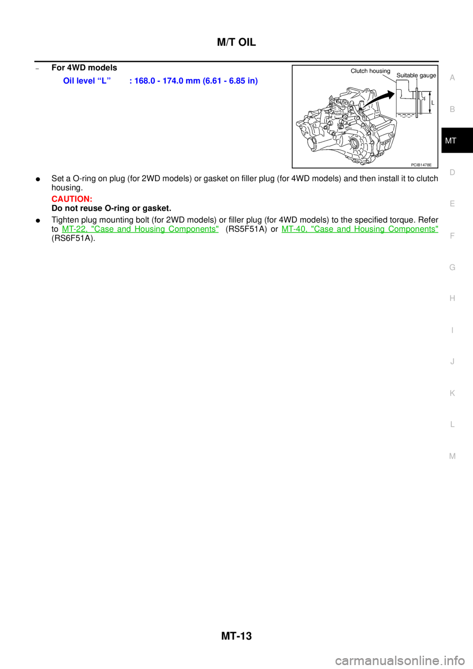
–For 4WD models
�Set a O-ring on plug (for 2WD models) or gasket on filler plug (for 4WD models) and then install it to clutch
housing.
CAUTION:
Do not reuse O-ring or gasket.
�Tighten plug mounting bolt (for 2WD models) or filler plug (for 4WD models) to the specified torque. Refer
to MT-22, "
Case and Housing Components" (RS5F51A) or MT-40, "Case and Housing Components"
(RS6F51A).Oil level “L” : 168.0 - 174.0 mm (6.61 - 6.85 in)
PCIB1478E
Page 2170 of 4555
MT-14
SIDE OIL SEAL
SIDE OIL SEALPFP:32113
Removal and InstallationECS008BT
REMOVAL
�Clutch housing side oil seal used on 4WD vehicles is attached to transfer. Be sure to replace it
when transfer is removed.
1. Remove drive shaft from transaxle. Refer to FAX-11, "
Removal and Installation" .
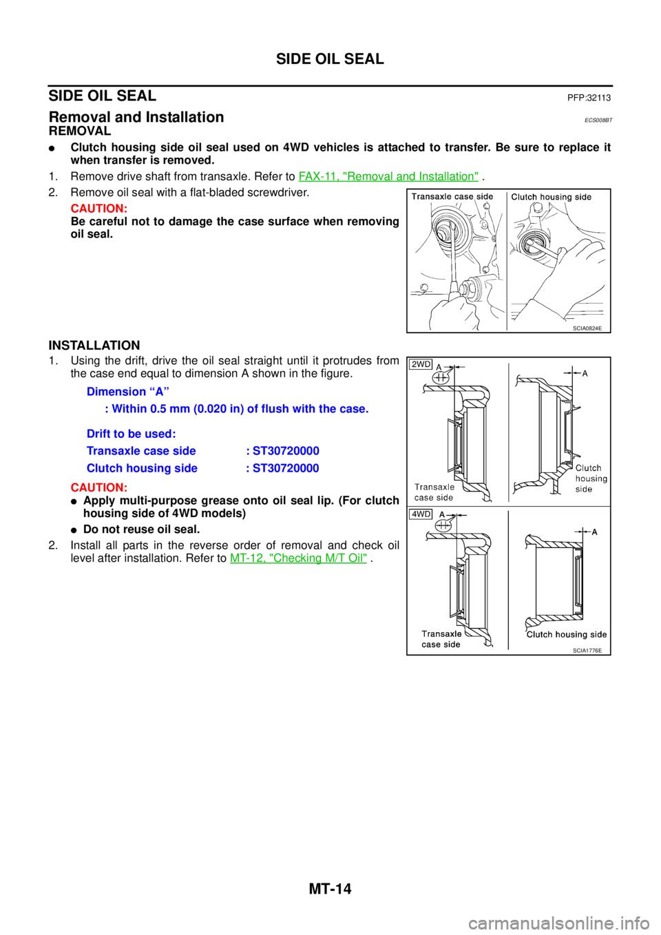
2. Remove oil seal with a flat-bladed screwdriver.
CAUTION:
Be careful not to damage the case surface when removing
oil seal.
INSTALLATION
1. Using the drift, drive the oil seal straight until it protrudes from
the case end equal to dimension A shown in the figure.
CAUTION:
�Apply multi-purpose grease onto oil seal lip. (For clutch
housing side of 4WD models)
�Do not reuse oil seal.
2. Install all parts in the reverse order of removal and check oil
level after installation. Refer to MT-12, "
Checking M/T Oil" .
SCIA0824E
Dimension “A”
: Within 0.5 mm (0.020 in) of flush with the case.
Drift to be used:
Transaxle case side : ST30720000
Clutch housing side : ST30720000
SCIA1776E
Page 2176 of 4555

MT-20
TRANSAXLE ASSEMBLY
4WD models
REMOVAL
1. Disconnect the battery cable from the negative terminal.
2. Remove air cleaner, air duct and battery. Refer to EM-16, "
Removal and Installation" (QR engine models)
or EM-142, "
Removal and Installation" (YD engine models).
3. Remove air breather hose. Refer to MT-18, "
Removal and Installation" .
4. Remove clutch operating cylinder. Refer to CL-12, "
Removal and Installation" .
CAUTION:
Do not depress clutch pedal during removal procedure.
5. Disconnect control cable from transaxle assembly. Refer to MT-17, "
Removal and Installation" .
6. Drain gear oil. Refer to MT-12, "
DRAINING" .
7. Disconnect PNP switch, back-up lamp switch and ground harness connectors.
8. Remove exhaust front tube. Refer to EX-2, "
Removal and Installation" .
9. Remove drive shaft. Refer to FAX-11, "
FRONT DRIVE SHAFT" .
10. Remove transfer (for 4WD models). Refer to TF-57, "
Removal and Installation" .
11. Remove starter motor. Refer to SC-27, "
Removal and Installation" .
12. Support transaxle assembly with a jack.
CAUTION:
When setting a jack, be careful not to bring it into contact with switches.
13. Remove center member, engine insulator and engine mount bracket. Refer to EM-81, "
ENGINE ASSEM-
BLY" (QR engine models) or EM-222, "ENGINE ASSEMBLY" (YD engine models).
14. Remove suspension members (for 4WD models). Refer to FSU-12, "
FRONT SUSPENSION MEMBER" .
15. Support engine with a jack under oil pan.
16. Remove transaxle assembly mounting bolts.
PCIB1476E
1. Center member 2. Front engine mounting insulator 3. Grommet
4. Transaxle assembly 5. Rear engine mounting bracket 6. Rear engine mounting insulator
7. LH engine mounting insulator 8. Stopper 9. LH engine mounting bracket
Page 2177 of 4555

TRANSAXLE ASSEMBLY
MT-21
D
E
F
G
H
I
J
K
L
MA
B
MT
17. Remove transaxle assembly from the vehicle.
CAUTION:
Secure transaxle assembly to a jack while removing it.
INSTALLATION
Note the following, and install in the reverse order of removal.
�When installing the transaxle assembly to the engine, install the mounting bolts following the standard
below.
CAUTION:
When installing transaxle assembly, be careful not to bring transaxle input shaft into contact with
clutch cover.
–QR engine models
*: Tightening the bolt for 4WD models.
–YD engine models
�After installation, check oil level, and check for leaks and loose
mechanisms. Refer to MT-12, "
Checking M/T Oil" .
MTD0062D
Bolt No. 1 2 3* 4 5 6
Quantity 2 1 1 2 2 2
Bolt length “ ”
mm (in)40
(1.57)75
(2.95)45
(1.77)40
(1.57)30
(1.18)40
(1.57)
Tightening torque
N·m (kg - m, ft- lb)74.5
(7.6, 55)42.7
(4.4, 31)35.3
(3.6, 26)
SCIA0353E
Bolt No. 1 2 3 4 5 6
Quantity 2 2 1 1 3 1
Bolt length “ ”
mm (in)55
(2.17)50
(2.76)120
(4.72)45
(1.77)40
(1.57)35
(1.38)
Tightening torque
N·m (kg - m, ft- lb)44
(4.5, 32)33.5
(3.4, 25)
SCIA0748E
Page 2182 of 4555
MT-26
TRANSAXLE ASSEMBLY
Final Drive Components
DISASSEMBLY
1. Remove plug (for 2WD models) or filler plug (for 4WD models) from clutch housing.
2. Remove drain plug and plug from transaxle case.
3. Remove park/neutral position switch and back-up lamp switch
from transaxle case.
4. Remove shift check and stopper bolt from transaxle case, and
then remove control assembly from transaxle case.
1. Differential side bearing outer race
(clutch housing side)2. Differential side bearing (clutch
housing side)3. Speedometer drive gear (for 2WD
models)
4. Differential case 5. Final gear 6. Differential side bearing (transaxle
case side)
7. Differential side bearing outer race
(transaxle case side)8. Differential side bearing adjusting
shim9. Pinion mate shaft
10. Side gear 11. Side gear thrust washer 12. Pinion mate gear
13. Pinion mate thrust washer 14. Retaining pin
PCIB0869E
SCIA0389E
Page 2186 of 4555
MT-30
TRANSAXLE ASSEMBLY
35. Remove input shaft oil seal from clutch housing.
CAUTION:
Be careful not to damage clutch housing.
ASSEMBLY
1. Install input shaft oil seal to clutch housing using the drift.
CAUTION:
Do not reuse input shaft oil seal.
2. Install differential side oil seal until it become flush with end face
of clutch housing using the drift.
CAUTION:
�Do not reuse differential side oil seal.
�Apply multi-purpose grease onto oil seal lip. (For 4WD
models)
3. Install oil channel on mainshaft side.
CAUTION:
Be careful with the orientation of installation.
SCIA0398E
Dimension A: 1.8 - 2.8 mm (0.071 - 0.110 in)
PCIB0873E
SCIA1070J
SCIA0986E
Page 2191 of 4555

TRANSAXLE ASSEMBLY
MT-35
D
E
F
G
H
I
J
K
L
MA
B
MT
30. Install bore plug to transaxle case using the drift.
CAUTION:
Do not reuse bore plug.
31. Install welch plug to transaxle case using the drift.
CAUTION:
Do not reuse welch plug.
32. Install 2 check balls, 2 check springs and 2 check plugs to tran-
saxle case, and then tighten check plug to the specified torque.
Refer to MT-25, "
Shift Control Components" .
CAUTION:
Do not reuse check plug.
33. Apply recommended sealant to threads of park/neutral position
switch and back-up lamp switch. Then install them to transaxle
case and tighten to the specified torque. Refer to MT-22, "
Case
and Housing Components" .
34. Install gaskets onto drain plug and plug, and then install them
into transaxle case. Tighten drain plug and plug to the specified
torque. Refer to MT-22, "
Case and Housing Components" .
CAUTION:
Do not reuse gasket.
35. Install O-ring onto plug (for 2WD models) or gasket onto filler
plug (for 4WD models), and then install it into clutch housing.
Tighten plug mounting bolt or filler plug to the specified torque.
Refer to MT-22, "
Case and Housing Components" .
CAUTION:
�Do not reuse O-ring or gasket.
�After oil is filled, tighten plug mounting bolt or filler plug to specified torque.
SCIA0894E
SCIA0403E
SCIA1668J
SCIA0895E
Page 2200 of 4555
MT-44
TRANSAXLE ASSEMBLY
Final Drive Components
DISASSEMBLY
1. Remove plug (for 2WD models) or filler plug (for 4WD models) from clutch housing.
2. Remove drain plug and plug from transaxle case.
3. Remove park/neutral position switch and back-up lamp switch
from transaxle case.
4. Remove shift check and stopper bolt from transaxle case, and
then remove control assembly from transaxle case.
1. Differential side bearing outer race
(clutch housing side)2. Differential side bearing (clutch
housing side)3. Speedometer drive gear (for 2WD
models)
4. Differential case 5. Final gear 6. Differential side bearing (transaxle
case side)
7. Differential side bearing outer race
(transaxle case side)8. Differential side bearing adjusting
shim9. Pinion mate shaft
10. Side gear 11. Side gear thrust washer 12. Pinion mate gear
13. Pinion mate thrust washer 14. Retaining pin
PCIB0869E
SCIA0389E
 or filler plug (for 4WD models) from clutch housing.
2. Remove drain plug and plug from transaxle case.
3.")

 or filler plug (for 4WD models) from clutch housing.
2. Remove drain plug and plug from transaxle case.
3.")