Page 181 of 4555
![NISSAN X-TRAIL 2005 Service Repair Manual SERVICE DATA AND SPECIFICATIONS (SDS)
EM-127
[QR]
C
D
E
F
G
H
I
J
K
L
MA
EM
CONNECTING ROD BEARING
Undersize
Unit: mm (in)
Bearing Oil Clearance
Unit: mm (in)
Tightening TorqueEBS00KNY
Unit: N·m (k](/manual-img/5/57403/w960_57403-180.png "NISSAN X-TRAIL 2005 Service Repair Manual SERVICE DATA AND SPECIFICATIONS (SDS)
EM-127
[QR]
C
D
E
F
G
H
I
J
K
L
MA
EM
CONNECTING ROD BEARING
Undersize
Unit: mm (in)
Bearing Oil Clearance
Unit: mm (in)
Tightening TorqueEBS00KNY
Unit: N·m (k")
SERVICE DATA AND SPECIFICATIONS (SDS)
EM-127
[QR]
C
D
E
F
G
H
I
J
K
L
MA
EM
CONNECTING ROD BEARING
Undersize
Unit: mm (in)
Bearing Oil Clearance
Unit: mm (in)
Tightening TorqueEBS00KNY
Unit: N·m (kg-m, ft-lb)
Unit: N·m (kg-m, in-lb)*2
Grade number Thickness mm (in) Identification color
0 1.495 - 1.499 (0.0589 - 0.0590) Black
1 1.499 - 1.503 (0.0590 - 0.0592) Brown
2 1.503 - 1.507 (0.0592 - 0.0593) Green
3 1.507 - 1.511(0.0593 - 0.0595) Yellow
Item Thickness Crank pin journal diameter
US 0.25 (0.0098) 1.624 - 1.632 (0.0639 - 0.0643) Grind so that bearing clearance is the specified value.
Connecting rod bearing oil clearanceStandard 0.028 - 0.045 (0.0011 - 0.0018)
Limit 0.10 (0.0039)
*1: Parts to be tightened in particular orders.
1)-: Order of tightening when tightening two or more times separately.
Drive belt auto-tensioner 21.6 (2.2, 16)
Mass air flow sensor
3.8 (0.39, 34) *
2
Resonator
3.8 (0.39, 34)*2
Air cleaner case lower
3.8 (0.39, 34)*2
*1 Intake manifold19.6 (2.0, 14)
Intake manifold collector (QR25DE) 19.6 (2.0, 14)
Intake manifold support (QR20DE) 19.6 (2.0, 14)
Intake manifold support (QR25DE) M6 bolt
8.83 (0.90, 78) *
2
M10 bolt 46.6 (4.8, 34)
Intake manifold rear support (QR25DE) 19.6 (2.0, 14)
Electric throttle control actuator
8.43 (0.86, 75) *
2
EVAP canister purge volume control solenoid valve
5.1 (0.52, 45) *2
*1 Exhaust manifold and three way catalyst assembly 41.7 (4.3, 31)
Exhaust manifold covers (upper and lower)
5.8 (0.59, 51) *
2
Three way catalyst cover
5.8 (0.59, 51) *2
Heated oxygen sensor 1 45 (4.6, 33)
Heated oxygen sensor 2 45 (4.6, 33)
*1 Oil pan upper M6 bolt
8.8 (0.90, 78) *
2
M8 bolt 21.6 (2.2, 16)
Oil pan upper to transaxle joint bolts 42.7 (4.4, 31)
*1 Oil pan lower
6.9 (0.70, 61) *
2
Oil pan drain plug34.3 (3.5, 25)
Rear plate cover
6.9 (0.70, 61) *
2
Oil level gauge guide 21.6 (2.2, 16)
Page 184 of 4555
![NISSAN X-TRAIL 2005 Service Repair Manual EM-130
[YD22DDTi]
PRECAUTIONS
[YD22DDTi]PRECAUTIONSPFP:00001
Precautions for Draining Engine CoolantEBS00LQZ
Drain engine coolant when engine is cooled.
Precautions for Disconnecting Fuel PipingEBS0](/manual-img/5/57403/w960_57403-183.png "NISSAN X-TRAIL 2005 Service Repair Manual EM-130
[YD22DDTi]
PRECAUTIONS
[YD22DDTi]PRECAUTIONSPFP:00001
Precautions for Draining Engine CoolantEBS00LQZ
Drain engine coolant when engine is cooled.
Precautions for Disconnecting Fuel PipingEBS0")
EM-130
[YD22DDTi]
PRECAUTIONS
[YD22DDTi]PRECAUTIONSPFP:00001
Precautions for Draining Engine CoolantEBS00LQZ
Drain engine coolant when engine is cooled.
Precautions for Disconnecting Fuel PipingEBS00LR0
�Before starting work, make sure no fire or spark producing items are in the work area.
�After disconnecting pipes, plug openings to stop fuel leakage.
Precautions for Removal and DisassemblyEBS00LR1
�When instructed to use special service tools, use the specified tools. Always be careful to work safely,
avoid forceful or uninstructed operations.
�Exercise maximum care to avoid damage to mating or sliding surfaces.
�Cover openings of engine system with tape or the equivalent, if necessary, to seal out foreign materials.
�Mark and arrange disassembly parts in an organized way for easy troubleshooting and re-assembly.
�When loosening nuts and bolts, as a basic rule, start with the one furthest outside, then the one diagonally
opposite, and so on. If the order of loosening is specified, do exactly as specified.
Precautions for Inspection, Repair and ReplacementEBS00LR2
Before repairing or replacing, thoroughly inspect parts. Inspect new replacement parts in the same way, and
replace if necessary.
Precautions for Assembly and InstallationEBS00LR3
�Use torque wrench to tighten bolts or nuts to specification.
�When tightening nuts and bolts, as a basic rule, equally tighten in several different steps starting with the
ones in center, then ones on inside and outside diagonally in this order. If the order of tightening is speci-
fied, do exactly as specified.
�Replace with new liquid gasket, packing, oil seal or O-ring.
�Dowel pins are used for several parts alignment. When replacing and reassembling parts with dowel pins,
make sure that dowel pins are installed in the original position.
�Thoroughly wash, clean, and air-blow each part. Carefully check engine oil or engine coolant passages for
any restriction and blockage.
�Avoid damaging sliding or mating surfaces. Completely remove foreign materials such as cloth lint or dust.
Before assembly, engine oil sliding surfaces well.
�Release air within route when refilling after draining coolant.
�After repairing, start engine and increase engine speed to check engine coolant, fuel, engine oil, and
exhaust systems for leakage.
Parts Requiring Angle TighteningEBS00LR4
�Use an angle wrench (special service tool: KV10112100) for the final tightening of the following engine
parts:
–Cylinder head bolts
–Main bearing cap bolts
–Connecting rod cap nuts
–Crankshaft pulley bolt (No angle wrench is required as the bolt flange is provided with notches for angle
tightening)
�Do not use a torque value for final tightening.
�The torque value for these parts are for a preliminary step.
�Ensure thread and seat surfaces are clean and coated with engine oil.
Page 195 of 4555
![NISSAN X-TRAIL 2005 Service Repair Manual DRIVE BELTS
EM-141
[YD22DDTi]
C
D
E
F
G
H
I
J
K
L
MA
EM
A/C COMPRESSOR BELT
1. Remove RH engine undercover.
2. Loosen idler pulley lock nut (A).
3. Turn adjusting bolt (B) to adjust. Refer to EM-140](/manual-img/5/57403/w960_57403-194.png "NISSAN X-TRAIL 2005 Service Repair Manual DRIVE BELTS
EM-141
[YD22DDTi]
C
D
E
F
G
H
I
J
K
L
MA
EM
A/C COMPRESSOR BELT
1. Remove RH engine undercover.
2. Loosen idler pulley lock nut (A).
3. Turn adjusting bolt (B) to adjust. Refer to EM-140")
DRIVE BELTS
EM-141
[YD22DDTi]
C
D
E
F
G
H
I
J
K
L
MA
EM
A/C COMPRESSOR BELT
1. Remove RH engine undercover.
2. Loosen idler pulley lock nut (A).
3. Turn adjusting bolt (B) to adjust. Refer to EM-140, "
Checking
Drive Belts" .
4. Tighten lock nut (A).
ALTERNATOR AND WATER PUMP BELT
1. Loosen adjusting lock nut (C).
2. Loosen alternator fixing bolts (D) (each on front and rear).
3. Turn adjusting bolt (E) to adjust. Refer to EM-140, "
Checking Drive Belts" .
4. Tighten nut (C) and bolt (D) in this order.
Removal and InstallationEBS00LRC
REMOVAL
1. Loosen each belt. Refer to EM-140, "Tension Adjustment" .
2. Remove A/C compressor belt. Refer to EM-141, "
A/C COMPRESSOR BELT" .
3. Remove alternator and water pump belt. Refer to EM-141, "
ALTERNATOR AND WATER PUMP BELT" .
INSTALLATION
1. Install each belt on pulley in the reverse order of removal.
2. Adjust belt tension. Refer to EM-140, "
Tension Adjustment" .
3. Tighten nuts and bolts provided for adjustment to the specified torque.
4. Make sure again that each belt tension is as specified.Nut A:
: 35 N·m (3.6 kg-m, 26 ft-lb)
PBIC1252E
Nut C:
: 21.5 N·m (2.2 kg-m, 16 ft-lb)
Bolt D:
: 50.5 N·m (5.2 kg-m, 37 ft-lb)
Page 202 of 4555
EM-148
[YD22DDTi]
INTAKE MANIFOLD
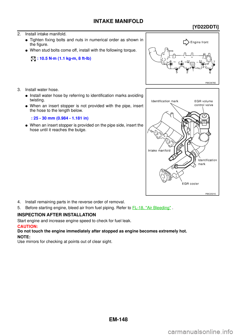
2. Install intake manifold.
�Tighten fixing bolts and nuts in numerical order as shown in
the figure.
�When stud bolts come off, install with the following torque.
3. Install water hose.
�Install water hose by referring to identification marks avoiding
twisting.
�When an insert stopper is not provided with the pipe, insert
the hose to the length below.
�When an insert stopper is provided on the pipe side, insert the
hose until it reaches the bulge.
4. Install remaining parts in the reverse order of removal.
5. Before starting engine, bleed air from fuel piping. Refer to FL-18, "
Air Bleeding" .
INSPECTION AFTER INSTALLATION
Start engine and increase engine speed to check for fuel leak.
CAUTION:
Do not touch the engine immediately after stopped as engine becomes extremely hot.
NOTE:
Use mirrors for checking at points out of clear sight. : 10.5 N·m (1.1 kg-m, 8 ft-lb)
PBIC0676E
: 25 - 30 mm (0.984 - 1.181 in)
PBIC2021E
Page 204 of 4555
EM-150
[YD22DDTi]
CATALYST
INSTALLATION
Note the following, and install in the reverse order of removal.
�Pushing gussets against the oil pan and the catalyst, temporarily tighten the mounting bolt. And then
tighten it to the specified torque.
�Assemble catalyst insulator with making clearance from catalyst.
Page 206 of 4555
![NISSAN X-TRAIL 2005 Service Repair Manual EM-152
[YD22DDTi]
EXHAUST MANIFOLD AND TURBOCHARGER
12. Remove turbocharger insulator.
13. Remove oil feed tube.
14. Loosen exhaust manifold mounting nuts in reverse order in the
figure.
15. Rotate](/manual-img/5/57403/w960_57403-205.png "NISSAN X-TRAIL 2005 Service Repair Manual EM-152
[YD22DDTi]
EXHAUST MANIFOLD AND TURBOCHARGER
12. Remove turbocharger insulator.
13. Remove oil feed tube.
14. Loosen exhaust manifold mounting nuts in reverse order in the
figure.
15. Rotate")
EM-152
[YD22DDTi]
EXHAUST MANIFOLD AND TURBOCHARGER
12. Remove turbocharger insulator.
13. Remove oil feed tube.
14. Loosen exhaust manifold mounting nuts in reverse order in the
figure.
15. Rotate exhaust manifold and turbocharger assembly so that the rear side (EGR cooler mounting side)
faces upward. And then pull out the assembly from between the engine and the A/C piping.
CAUTION:
Be careful not to deform each turbocharger piping when pulling out the assembly.
16. Remove exhaust manifold gasket.
CAUTION:
Cover engine openings to avoid entry of foreign materials.
INSTALLATION
�When a stud bolt is pulled out, tighten it to the following torque:
�Tighten the exhaust manifold mounting nuts in the following procedure:
1. Install gasket so that the alignment protrusion faces the No. 4 port. Refer to EM-151, "
Removal and Instal-
lation" .
2. Tighten the nuts in order specified in the figure.
3. Re-tighten the nuts 1 to 4.
4. Install in the reverse order of removal.
INSPECTION AFTER INSTALLATION
Start engine and raise engine speed to check no exhaust gas and engine oil leaks.
JEM266G
: 14.7 N·m (1.5 kg-m, 11ft-lb)
JEM266G
Page 207 of 4555
EXHAUST MANIFOLD AND TURBOCHARGER
EM-153
[YD22DDTi]
C
D
E
F
G
H
I
J
K
L
MA
EM
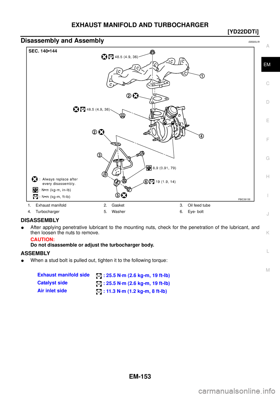
Disassembly and AssemblyEBS00LRI
DISASSEMBLY
�After applying penetrative lubricant to the mounting nuts, check for the penetration of the lubricant, and
then loosen the nuts to remove.
CAUTION:
Do not disassemble or adjust the turbocharger body.
ASSEMBLY
�When a stud bolt is pulled out, tighten it to the following torque:
1. Exhaust manifold 2. Gasket 3. Oil feed tube
4. Turbocharger 5. Washer 6. Eye- bolt
PBIC3613E
Exhaust manifold side
: 25.5 N·m (2.6 kg-m, 19 ft-lb)
Catalyst side
: 25.5 N·m (2.6 kg-m, 19 ft-lb)
Air inlet side
: 11.3 N·m (1.2 kg-m, 8 ft-lb)
Page 214 of 4555
![NISSAN X-TRAIL 2005 Service Repair Manual EM-160
[YD22DDTi]
OIL PAN AND OIL STRAINER
�Tighten bolts in numerical order to the specified torque.
�Bolt dimensions vary depending on the installation location.
Refer to the following and use app](/manual-img/5/57403/w960_57403-213.png "NISSAN X-TRAIL 2005 Service Repair Manual EM-160
[YD22DDTi]
OIL PAN AND OIL STRAINER
�Tighten bolts in numerical order to the specified torque.
�Bolt dimensions vary depending on the installation location.
Refer to the following and use app")
EM-160
[YD22DDTi]
OIL PAN AND OIL STRAINER
�Tighten bolts in numerical order to the specified torque.
�Bolt dimensions vary depending on the installation location.
Refer to the following and use appropriate bolts.
�The shank length under the bolt neck above is the length of
the threaded part (pilot portion not included).
2. Install oil strainer.
3. Tighten transaxle joint bolts.
4. Install rear plate cover.
5. Install center member. Refer to EM-222, "
ENGINE ASSEMBLY" .
6. Install crankshaft position sensor.
7. Install oil pan lower as follows:
a. Use a scraper to remove old liquid gasket from mating surfaces.
CAUTION:
�Also remove old liquid gasket from mating surface of oil
pan upper.
�Remove old liquid gasket from bolt hole and thread.
b. Apply a continuous bead of liquid gasket with the tube presser
(special service tool: WS39930000) as shown in the figure.
Use Genuine Liquid Gasket or equivalent.
�Be sure liquid gasket is 3.5 to 4.5 mm (0.138 to 0.177 in)
wide.
�Attaching should be done within 5 minutes after coating.M6 x 30 mm (1.18 in) : Bolt No. 15, 16
M8 x 25 mm (0.98 in) : Bolt No. 3, 4, 9, 10
M8 x 60 mm (2.36 in) : Bolt No. 1, 2, 5, 6, 7, 8,
11, 12, 13, 14
SBIA0162E
PBIC2277E
SBIA0163E
SBIA0164E