Page 3485 of 4555
 into rack assembly piston (rack Teflon
ring). Push retainer to adjusting screw side by hand, and move")
POWER STEERING GEAR AND LINKAGE
PS-23
C
D
E
F
H
I
J
K
L
MA
B
PS
b. Insert rack oil seal (inner) into rack assembly piston (rack Teflon
ring). Push retainer to adjusting screw side by hand, and move
the rack assembly inside the gear housing assembly so that the
rack oil seal (inner) can be pressed against the gear housing
assembly.
c. Wrap an OHP sheet [approximately 70 mm (2.76 in)×100 mm
(3.94 in).] Around the edge to avoid damaging rack oil seal
(outer). Install rack oil seal over sheet. Then, pull oil seal along
with OHP sheet until they pass rack edge, and remove OHP
sheet.
d. Install end cover assembly to rack edge, and move rack assem-
bly until it contacts with gear housing assembly.
5. Tighten end cover assembly to specified torque using a 36 mm
(1.42 in) open head (suitable tool).
CAUTION:
Do not damage rack assembly. Replace it if damaged
because it may cause oil leakage.
6. Crimp gear housing assembly at one point using a punch as
shown in the figure so as to prevent end cover assembly from
getting loose after tightening end cover assembly.
7. Apply Type DEXRON
TM III or equivalent to O-ring C, and then
install O-ring C to gear housing assembly.
8. Install gear sub assembly to gear housing assembly.
9. Install inner socket to rack assembly according to the instruc-
tions.
a. Attach spacer ring to rack assembly.
b. Install lock plate to inner socket.
c . A p p l y l o c k i n g s e a l a n t ( T h r e e B o n d T B 1111 o r e q u i v a l e n t ) t o t h e
thread of inner socket. Screw inner socket into rack assembly
and tighten at the specified torque.
d. Clinch lock plate at two points on rack groove.
e. Install spacer ring to lock plate as shown in the figure.
SGIA0935E
SGIA0157E
SST081B
SGIA0871E
SST866C
Page 3486 of 4555

PS-24
POWER STEERING GEAR AND LINKAGE
CAUTION:
When installing spacer ring, avoid damaging it.
10. Decide on the neutral position for the rack.
11. Install rear cover cap to gear sub assembly.
CAUTION:
Make sure that the projection of rear cover cap is aligned
with the marking position of gear housing assembly.
1 2 . A p p l y a c o a t o f T h r e e B o n d T B 1111 o r e q u i v a l e n t t o t h e t h r e a d
(2 turns thread), and then screw in the adjusting screw until it
reaches height “H” from gear housing assembly measured
before disassembling.
13. Move rack 10 strokes throughout the full stroke so that the parts
can fit with each other.
14. Measure pinion rotating torque within ±180° of neutral position
of the rack using the preload gauge [SST] and preload adapter
[SST]. Stop the gear at the point where highest torque is read.
15. Loosen adjusting screw and retighten to 5.4 N·m (0.55 kg-m, 48
in-lb), and then loosen by 20 to 40°.
16. Measure pinion rotating torque using the steering gear preload
adapter [SST] and preload gauge [SST] to make sure that the
measured value is within the standard. Readjust if the value is
outside the standard. Replace gear assembly if the value is out
side the standard after readjusting or adjusting screw rotating
torque is 5 N·m (0.51 kg-m, 44 in-lb) or less.
1 7 . A p p l y a c o a t o f T h r e e B o n d T B 1111 o r e q u i v a l e n t t o i n n e r s o c k e t a n d t u r n p i n i o n f u l l y t o l e f t w i t h i n n e r
socket installed to gear housing assembly.Rack stroke “L” : 66.5 mm (2.618 in)
SGIA0629J
SGIA0624E
STC0036D
Pinion rotating torque standard
Around neutral position
(Within±100°) Average A1.67–2.25 N·m
(0.17 – 0.22 kg-m, 1.3 – 1.6 ft-lb)
Maximum variation B 0.98 N·m (0.10 kg-m, 1 ft-lb)
SGIA0936E
Page 3487 of 4555

POWER STEERING GEAR AND LINKAGE
PS-25
C
D
E
F
H
I
J
K
L
MA
B
PS
18. Set dial gauge as shown in the figure. Measure vertical move-
ment of rack assembly when pinion is turned clockwise with
torque of 4.9 N·m (0.5 kg-m, 43 in-lb). Readjust adjusting screw
angle if the measured value is outside the standard. Replace
gear assembly if the measured value is still outside the standard
or adjusting screw rotating torque is 4.9 N·m (0.5 kg-m, 43 in-lb)
or less.
19. Install large end of boot to gear housing assembly.
20. Install small end of boot to inner socket boot mounting groove.
21. Install boot clamp to boot small end.
22. Install large side of boot clamp.
NOTE:
Do not reuse large side of boot clamp.
�Tighten large side of boot with boot clamp (stainless wire).
�Wrap clamp around boot groove for two turns. Insert a flat-
bladed screwdriver in loops on both ends of wire. Twist 4 to
4.5 turns while pulling them with force of approximately 98 N
(10 kg, 22 lb).
�Twist boot clamp as shown. Pay attention to relationship
between winding and twisting directions.
SGIA0465E
Vertical movement of rack 0.265 mm (0.0104 in) or less
Measuring pointRack axial direction 5 mm (0.197 in) from housing end surface
Rack radial direction Axial direction of the adjusting screw
SGIA0550E
Wire length “L” : 370 mm (14.57 in)
SGIA0163E
SGIA0164E
Page 3488 of 4555
PS-26
POWER STEERING GEAR AND LINKAGE
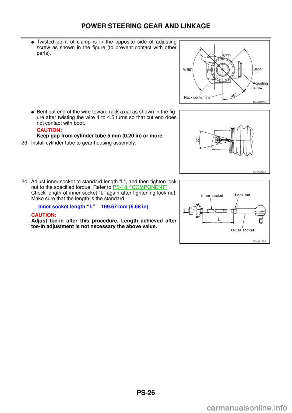
�Twisted point of clamp is in the opposite side of adjusting
screw as shown in the figure (to prevent contact with other
parts).
�Bent cut end of the wire toward rack axial as shown in the fig-
ure after twisting the wire 4 to 4.5 turns so that cut end does
not contact with boot.
CAUTION:
Keep gap from cylinder tube 5 mm (0.20 in) or more.
23. Install cylinder tube to gear housing assembly.
24. Adjust inner socket to standard length “L”, and then tighten lock
nut to the specified torque. Refer to PS-18, "
COMPONENT" .
Check length of inner socket “L” again after tightening lock nut.
Make sure that the length is the standard.
CAUTION:
Adjust toe-in after this procedure. Length achieved after
toe-in adjustment is not necessary the above value.
SGIA0214E
SGIA0260J
Inner socket length “L” 169.67 mm (6.68 in)
SGIA0167E
Page 3493 of 4555

POWER STEERING OIL PUMP
PS-31
C
D
E
F
H
I
J
K
L
MA
B
PS
9. Connect rotor snap ring to slit of pulley shaft, using a hammer
and a 10-mm socket.
CAUTION:
� Rotor snap ring is not reusable. Never reuse rotor snap
ring.
�Be careful not to damage rotor and pulley shaft.
�If rotor is damaged, power steering pump assembly must
be replaced.
10. Align dowel pin A on flow control valve A with notch B in side
plate (rear) as shown. Install side plate (rear) to cartridge.
11. Apply DEXRON
TM III or equivalent to body seal. Install it to cas-
ing.
CAUTION:
Body seal is not reusable. Never reuse body seal.
12. Apply DEXRON
TM III or equivalent to side plate inner and outer
seals. Install them to side plate (rear).
CAUTION:
Side plate inner and outer seals are not reusable. Never
reuse side plate inner and outer seals.
13. Fix power steering pump in a vise.
CAUTION:
When fixing pump in a vise, use aluminum plates to protect
steering pump mounting surface.
14. Attach rear body to casing and tighten four mounting bolts diag-
onally to specified torque.
15. Install rear bracket to rear body. Tighten mounting bolts to specified torque.
16. Connect front bracket to casing and tighten mounting bolts (3) to specified torque.
17. Connect inlet connector seal to inlet connector slit. Install inlet connector to casing with attaching bolts.
CAUTION:
Inlet connector seal is not reusable. Never reuse inlet connector seal.
SGIA0063E
SGIA0064E
SGIA0065E
Page 3505 of 4555
HYDRAULIC LINE
PS-43
C
D
E
F
H
I
J
K
L
MA
B
PS
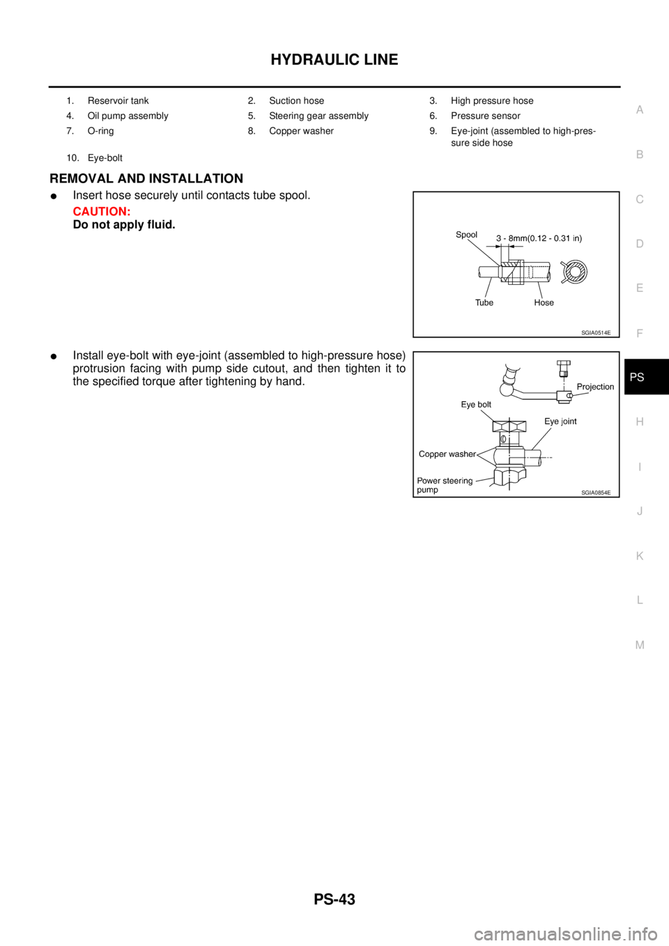
REMOVAL AND INSTALLATION
�Insert hose securely until contacts tube spool.
CAUTION:
Do not apply fluid.
�Install eye-bolt with eye-joint (assembled to high-pressure hose)
protrusion facing with pump side cutout, and then tighten it to
the specified torque after tightening by hand.
1. Reservoir tank 2. Suction hose 3. High pressure hose
4. Oil pump assembly 5. Steering gear assembly 6. Pressure sensor
7. O-ring 8. Copper washer 9. Eye-joint (assembled to high-pres-
sure side hose
10. Eye-bolt
SGIA0514E
SGIA0854E
Page 3506 of 4555

SERVICE DATA AND SPECIFICATIONS (SDS)PFP:00030
Steering WheelEGS0004P
Steering AngleEGS0004Q
Steering ColumnEGS0004R
Steering Outer Socket and Inner Socke")
PS-44
SERVICE DATA AND SPECIFICATIONS (SDS)
SERVICE DATA AND SPECIFICATIONS (SDS)PFP:00030
Steering WheelEGS0004P
Steering AngleEGS0004Q
Steering ColumnEGS0004R
Steering Outer Socket and Inner SocketEGS0004S
Steering wheel axial end play 0 mm (0 in)
Steering wheel play 0 - 35 mm (0 - 1.38 in)
Inner wheel
Degree minute (Decimal degree)Minimum 36° 00′ (36.0°)
Nominal 39° 00′ (39.0°)
Maximum 40° 00′ (40.0°)
Outer wheel
Degree minute (Decimal degree)31° 00′ (31.0°)
Steering column length “L” 405.3 mm (15.96 in)
SGIA0883E
Steering gear type PR24AD
Outer socketSwing torque 0.3 - 2.9 N·m (0.03 - 0.29 kg-m, 3.0 - 25 in-lb)
Measurement on spring balance
Measuring point: cotter pin hole of stud4.84 - 47.4 N (0.49 - 4.84 kg, 1.08 - 10.7 lb)
Rotating torque 0.3 - 2.9 N·m (0.03 - 0.29 kg-m, 3.0 - 25 in-lb)
Axial endplay 0.5 mm (0.02 in) or less
Inner socketSwing torque 1.0 - 7.8 N·m (0.10 - 0.80 kg-m, 9.0 - 69 in-lb)
�Measurement on spring balance
�Measuring point at* mark shown in the figure5.2 - 41 N (0.53 - 4.1 kg, 1.17 - 9.07 lb)
Axial endplay 0.2 mm (0.008 in) or less
Inner socket length “L” 169.67 mm (6.68 in)
SGIA0950E
Page 3594 of 4555
BL-12
HOOD
HOODPFP:65100
Fitting AdjustmentEIS009QH
LONGITUDINAL AND LATERAL CLEARANCE ADJUSTMENT
1. Remove hood lock assembly, loosen the hood hinge nuts and close the hood.
2. Adjust the lateral and longitudinal clearance, and open the hood to tighten the hood hinge mounting bolts
to the specified torque.
3. Install the hood lock temporarily, and align the hood striker and lock so that the centers of striker and lock
become vertical viewed from the front, by moving the hood lock laterally.
4. Tighten hood lock mounting bolts to the specified torque.
FRONT END HEIGHT ADJUSTMENT
1. Remove the hood lock and adjust the height by rotating the bumper rubber until the hood becomes 1 to1.5
mm (0.04 to 0.059 in) lower than the fender.
PIIB1215E