Page 3035 of 4555
REAR DISC BRAKE
BR-37
C
D
E
G
H
I
J
K
L
MA
B
BR
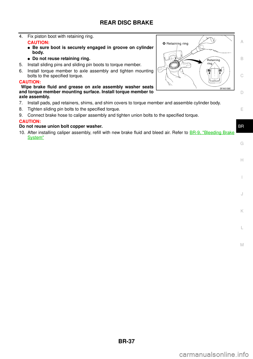
4. Fix piston boot with retaining ring.
CAUTION:
�Be sure boot is securely engaged in groove on cylinder
body.
�Do not reuse retaining ring.
5. Install sliding pins and sliding pin boots to torque member.
6. Install torque member to axle assembly and tighten mounting
bolts to the specified torque.
CAUTION:
Wipe brake fluid and grease on axle assembly washer seats
and torque member mounting surface. Install torque member to
axle assembly.
7. Install pads, pad retainers, shims, and shim covers to torque member and assemble cylinder body.
8. Tighten sliding pin bolts to the specified torque.
9. Connect brake hose to caliper assembly and tighten union bolts to the specified torque.
CAUTION:
Do not reuse union bolt copper washer.
10. After installing caliper assembly, refill with new brake fluid and bleed air. Refer to BR-9, "
Bleeding Brake
System"
SFIA0158E
Page 3040 of 4555
PB-2
PARKING BRAKE CONTROL
PARKING BRAKE CONTROLPFP:36010
Components EFS0017I
NOTE:
In regard to the notation of torque in the illustration, “NEW” shows an ISO standard, “OLD” shows a conven-
tional standard, and the measurements of hexagonal width across flats are in parentheses.
Removal and InstallationEFS0017J
REMOVAL
1. Remove center console.
2. Disconnect parking brake warning lamp switch connector.
3. Remove cable mounting bolt. Loosen cable and remove adjust-
ing nut.
4. Remove cable from toggle lever of disc brake.
INSTALLATION
CAUTION:
Do not reuse adjusting nut.
1. Operate parking brake lever with a force of 196 N (20 kg, 44 lb). Check a stroke is within specified number
of notches. (Check it by hearing clicks of ratchet.)
1. Control lever assembly 2. Cap 3. Parking brake warning lamp switch
4. Screw 5. Adjusting nut 6. Front cable
7. RH rear cable 8. LH rear cable :Multi-purpose grease
SFIA3052E
SFIA2453E
Lever stroke : 6 - 7 notches
Page 3045 of 4555
PARKING BRAKE SHOE
PB-7
C
D
E
G
H
I
J
K
L
MA
B
PB
2. Attach upper-side return springs to brake shoe as shown in the
figure. Be sure to install return spring B over return spring A.
3. Orientation of adjusters is different for LH adjuster and RH
adjuster. Assemble adjusters so that threaded part is expanded
when rotating it to direction shown by arrow. Contract adjuster to
assemble.
CAUTION:
When adjuster was disassembled, apply brake grease to thread.
4. Assemble torque lever in direction of installation as shown in the
figure.
SFIA0281E
SFIA2426E
SBR096C
Page 3052 of 4555
![NISSAN X-TRAIL 2005 Service Repair Manual BRC-4
[ABS]
PRECAUTIONS
[ABS]PRECAUTIONSPFP:00001
Precautions for Supplemental Restraint System (SRS) “AIR BAG” and “SEAT
BELT PRE-TENSIONER”
EFS005X6
The Supplemental Restraint System such](/manual-img/5/57403/w960_57403-3051.png "NISSAN X-TRAIL 2005 Service Repair Manual BRC-4
[ABS]
PRECAUTIONS
[ABS]PRECAUTIONSPFP:00001
Precautions for Supplemental Restraint System (SRS) “AIR BAG” and “SEAT
BELT PRE-TENSIONER”
EFS005X6
The Supplemental Restraint System such")
BRC-4
[ABS]
PRECAUTIONS
[ABS]PRECAUTIONSPFP:00001
Precautions for Supplemental Restraint System (SRS) “AIR BAG” and “SEAT
BELT PRE-TENSIONER”
EFS005X6
The Supplemental Restraint System such as “AIR BAG” and “SEAT BELT PRE-TENSIONER”, used along
with a front seat belt, helps to reduce the risk or severity of injury to the driver and front passenger for certain
types of collision. Information necessary to service the system safely is included in the SRS and SB section of
this Service Manual.
WARNING:
�To avoid rendering the SRS inoperative, which could increase the risk of personal injury or death
in the event of a collision which would result in air bag inflation, all maintenance must be per-
formed by an authorized NISSAN/INFINITI dealer.
�Improper maintenance, including incorrect removal and installation of the SRS, can lead to per-
sonal injury caused by unintentional activation of the system. For removal of Spiral Cable and Air
Bag Module, see the SRS section.
�Do not use electrical test equipment on any circuit related to the SRS unless instructed to in this
Service Manual. SRS wiring harnesses can be identified by yellow and/or orange harnesses or
harness connectors.
Precautions for Brake SystemEFS004GX
�Recommended fluid is brake fluid “DOT 3” or “DOT 4”.
�Do not reuse drained brake fluid.
�Be careful not to splash brake fluid on painted areas such as body. If brake fluid is splashed, wipe it off
and flush area with water immediately.
�Do not use mineral oils such as gasoline or kerosene to clean. They will ruin rubber parts and cause
improper operation.
�Using a flare nut torque wrench, securely tighten brake tube
flare nuts.
�Brake system is an important safety part. If a brake fluid leak is
detected, always disassemble the affected part. If a malfunction
is detected, replace part with a new one.
�Before working, turn ignition switch OFF and disconnect har-
ness connectors of ABS actuator and electric unit (control unit)
or battery cable from negative terminal.
�When installing brake piping, be sure to check torque.
Precautions for Brake ControlEFS004FV
�During ABS operation, brake pedal lightly vibrates and a mechanical noise may be heard. This is normal.
�Just after starting vehicle after ignition switch ON, brake pedal may vibrate or motor operating noise may
be heard from engine compartment. This is a normal status of operation check.
�Stopping distance may be longer than that of vehicles without ABS when vehicle drives on rough, gravel,
or snow-covered (fresh, deep snow) roads.
�When an malfunction is indicated by ABS or another warning lamp, collect all necessary information from
customer (what symptoms are present under what conditions) and check for simple causes before start-
ing diagnostic servicing. Besides electrical system inspection, check booster operation, brake fluid level,
and oil leaks.
�If tyre size and type are used in an improper combination, or brake pads are not Genuine NISSAN parts,
stopping distance or steering stability may deteriorate.
�If there is a radio, antenna, or antenna lead-in wire (including wiring) near control module, ABS function
may have a malfunction.
�If aftermarket parts (car stereo, CD player, etc.) Have been installed, check for incidents such as harness
pinches, open circuits, and improper wiring.
SBR820BA
Page 3053 of 4555
PREPARATION
BRC-5
[ABS]
C
D
E
G
H
I
J
K
L
MA
B
BRC
PREPARATIONPFP:00002
Special Service ToolsEFS004GU
Tool number
Tool nameDescription
GG94310000
Flare nut torque wrench
a: 10mm (0.39 in)Installing each brake piping
NT406
Page 3083 of 4555
![NISSAN X-TRAIL 2005 Service Repair Manual TROUBLE DIAGNOSIS
BRC-35
[ABS]
C
D
E
G
H
I
J
K
L
MA
B
BRC
Basic InspectionEFS004GD
BASIC INSPECTION 1 BRAKE FLUID AMOUNT, LEAKS, AND BRAKE PADS INSPECTION
1. Check fluid level in the brake reservoir](/manual-img/5/57403/w960_57403-3082.png "NISSAN X-TRAIL 2005 Service Repair Manual TROUBLE DIAGNOSIS
BRC-35
[ABS]
C
D
E
G
H
I
J
K
L
MA
B
BRC
Basic InspectionEFS004GD
BASIC INSPECTION 1 BRAKE FLUID AMOUNT, LEAKS, AND BRAKE PADS INSPECTION
1. Check fluid level in the brake reservoir")
TROUBLE DIAGNOSIS
BRC-35
[ABS]
C
D
E
G
H
I
J
K
L
MA
B
BRC
Basic InspectionEFS004GD
BASIC INSPECTION 1 BRAKE FLUID AMOUNT, LEAKS, AND BRAKE PADS INSPECTION
1. Check fluid level in the brake reservoir tank. If fluid level is low, refill the brake fluid.
2. Check the brake piping and around the ABS actuator for leaks. If there is leaking or oozing fluid, check the
following items.
�If ABS actuator and electric unit (control unit) connection is loose, tighten the piping to the specified
torque and re-conduct the leak inspection to make sure there are no leaks.
� If there is damage to the connection flare nut or ABS actuator and electric unit (control unit) screw,
replace the damaged part and re-conduct the leak inspection to make sure there are no leaks.
�When there is fluid leaking or oozing from a part other than ABS actuator and electric unit (control unit)
connection, if the fluid is just oozing out, use a clean cloth to wipe off the oozing fluid and re-check for
leaks. If fluid is still oozing out, replace the damaged part.
CAUTION:
ABS actuator and electric unit (control unit) cannot be disassembled.
3. Check the brake pad degree of wear. Refer to BR-27, "
PA D T H I C K N E S S" in “Front Disc Brake” and BR-
32, "PAD WEAR INSPECTION" in “Rear Disc Brake”.
BASIC INSPECTION 2 POWER SYSTEM TERMINAL LOOSENESS AND BATTERY INSPECTION
Make sure the battery positive cable, negative cable and ground connection are not loose. In addition, check
the battery voltage to make sure it has not dropped.
BASIC INSPECTION 3 ABS WARNING LAMP
1. Make sure that when the ignition switch is turned ON, the ABS warning lamp turns on for approximately 1
second. If they do not turn on, perform CAN communication system diagnosis. Refer to BRC-43, "
Inspec-
tion 7: CAN Communication System" .
2. Check if the ABS warning lamp turns off approximately 1 second after the ignition switch is turned ON, If it
do not turn off, perform self-diagnosis.
3. if ABS warning lamp has not turned off 10 seconds after the engine has been started, perform self-diagno-
sis of the ABS actuator and electric unit (control unit).
4. Always erase the self-diagnostic results after completing self-diagnosis. Refer to BRC-28, "
Operation Pro-
cedure" .
Page 3094 of 4555
![NISSAN X-TRAIL 2005 Service Repair Manual BRC-46
[ABS]
WHEEL SENSORS
WHEEL SENSORSPFP:47910
Removal and InstallationEFS004GR
REMOVAL
Pay attention to the following when removing sensor.
CAUTION:
�As much as possible, avoid rotating sensor w](/manual-img/5/57403/w960_57403-3093.png "NISSAN X-TRAIL 2005 Service Repair Manual BRC-46
[ABS]
WHEEL SENSORS
WHEEL SENSORSPFP:47910
Removal and InstallationEFS004GR
REMOVAL
Pay attention to the following when removing sensor.
CAUTION:
�As much as possible, avoid rotating sensor w")
BRC-46
[ABS]
WHEEL SENSORS
WHEEL SENSORSPFP:47910
Removal and InstallationEFS004GR
REMOVAL
Pay attention to the following when removing sensor.
CAUTION:
�As much as possible, avoid rotating sensor when removing it. Pull sensors out without pulling on
sensor harness.
�Take care to avoid damaging sensor edges or rotor teeth. Remove wheel sensor first before
removing front or rear wheel hub. This is to avoid damage to sensor wiring and loss of sensor
function.
INSTALLATION
Pay attention to the following when installing sensor. Tighten installation bolts to specified torques.
�When installing, check that there is no foreign material such as iron chips on pick-up and mounting hole of
the sensor. Check that no foreign material has been caught in the sensor rotor. Remove any foreign mate-
rial and clean the mount.
�When installing front sensor, be sure to press rubber grommets in until they lock at the three locations
shown in the figure (2 at strut and 1 at body panel). When installed, harness must not be twisted.
SFIA1100E
Page 3097 of 4555
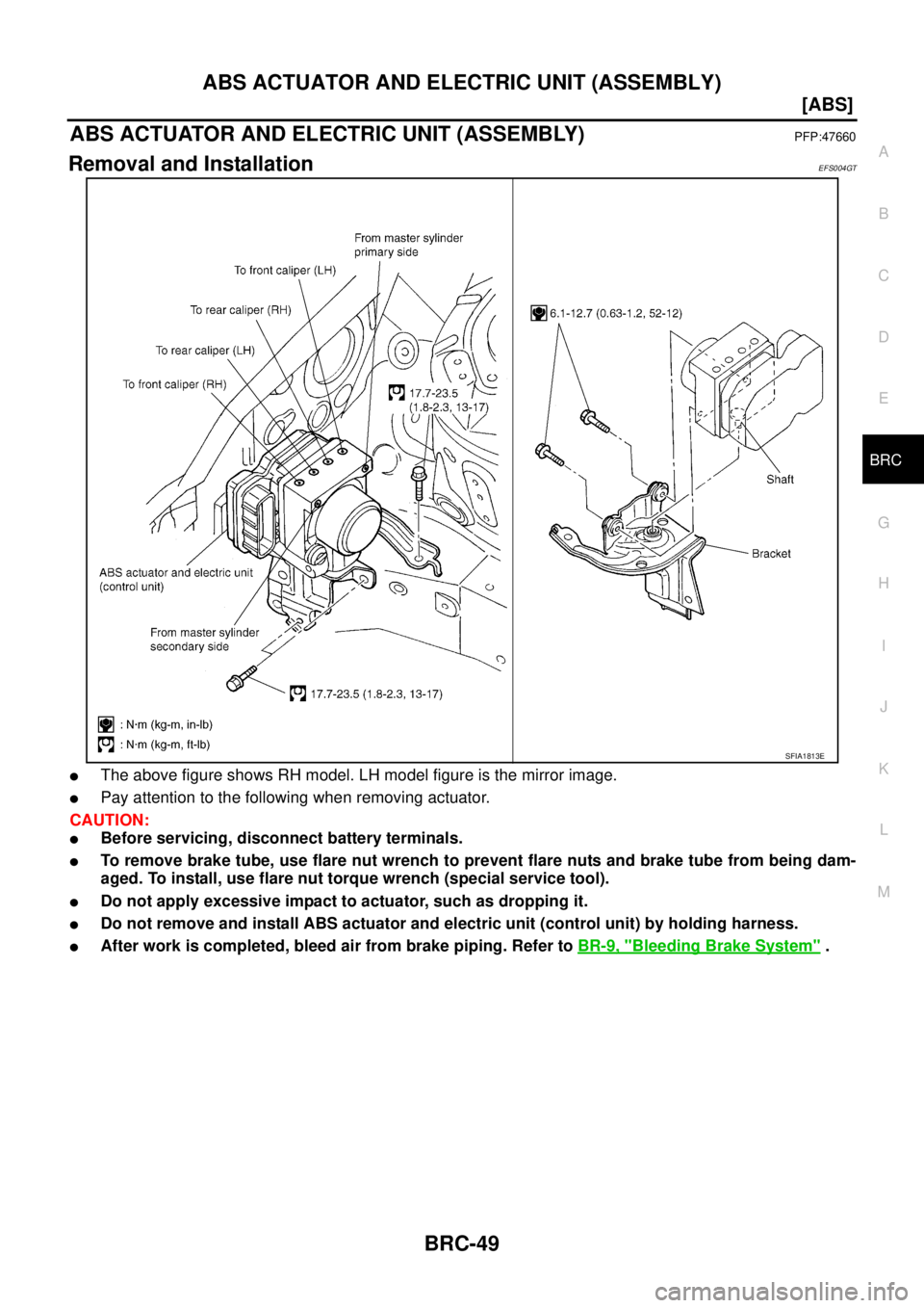
ABS ACTUATOR AND ELECTRIC UNIT (ASSEMBLY)
BRC-49
[ABS]
C
D
E
G
H
I
J
K
L
MA
B
BRC
ABS ACTUATOR AND ELECTRIC UNIT (ASSEMBLY)PFP:47660
Removal and InstallationEFS004GT
�The above figure shows RH model. LH model figure is the mirror image.
�Pay attention to the following when removing actuator.
CAUTION:
�Before servicing, disconnect battery terminals.
�To remove brake tube, use flare nut wrench to prevent flare nuts and brake tube from being dam-
aged. To install, use flare nut torque wrench (special service tool).
�Do not apply excessive impact to actuator, such as dropping it.
�Do not remove and install ABS actuator and electric unit (control unit) by holding harness.
�After work is completed, bleed air from brake piping. Refer to BR-9, "Bleeding Brake System" .
SFIA1813E


![NISSAN X-TRAIL 2005 Service Repair Manual PREPARATION
BRC-5
[ABS]
C
D
E
G
H
I
J
K
L
MA
B
BRC
PREPARATIONPFP:00002
Special Service ToolsEFS004GU
Tool number
Tool nameDescription
GG94310000
Flare nut torque wrench
a: 10mm (0.39 in)Installing](/manual-img/5/57403/w960_57403-3052.png "NISSAN X-TRAIL 2005 Service Repair Manual PREPARATION
BRC-5
[ABS]
C
D
E
G
H
I
J
K
L
MA
B
BRC
PREPARATIONPFP:00002
Special Service ToolsEFS004GU
Tool number
Tool nameDescription
GG94310000
Flare nut torque wrench
a: 10mm (0.39 in)Installing")