Page 3174 of 4555
EX-4
EXHAUST SYSTEM
�Temporarily tighten mounting nuts on the exhaust manifold side and mounting bolts on the vehi-
cle side. Check each part for unusual interference, and then tighten them to the specified torque.
�When installing each mounting rubber, avoid twisting or unusual extension in up/down and right/
left directions.
�Install seal bearings at exhaust front tube and main muffler as follows.
CAUTION:
Do not mix the bolt and spring for seal bearing as the dimension is different for each seal bearing.
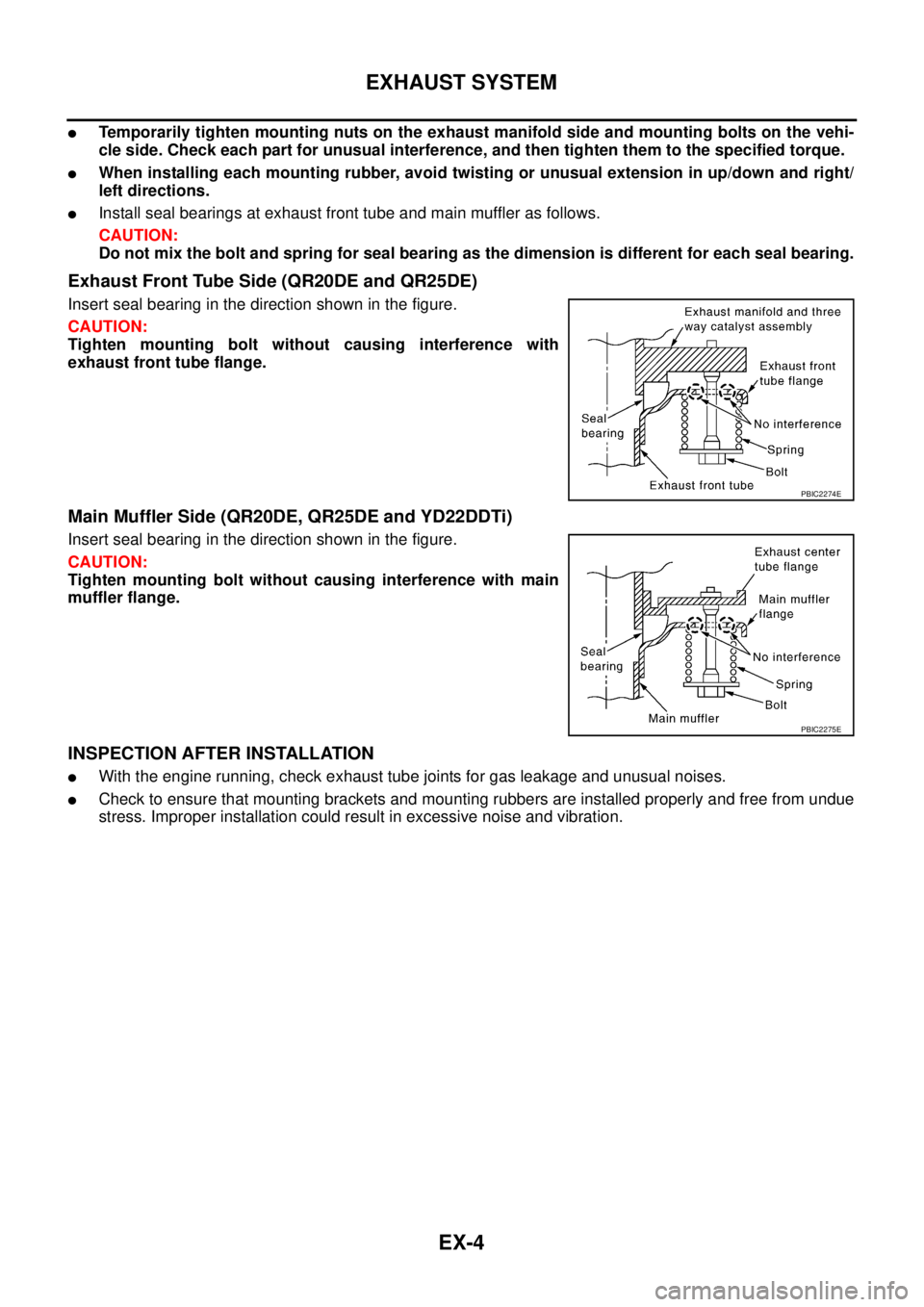
Exhaust Front Tube Side (QR20DE and QR25DE)
Insert seal bearing in the direction shown in the figure.
CAUTION:
Tighten mounting bolt without causing interference with
exhaust front tube flange.
Main Muffler Side (QR20DE, QR25DE and YD22DDTi)
Insert seal bearing in the direction shown in the figure.
CAUTION:
Tighten mounting bolt without causing interference with main
muffler flange.
INSPECTION AFTER INSTALLATION
�With the engine running, check exhaust tube joints for gas leakage and unusual noises.
�Check to ensure that mounting brackets and mounting rubbers are installed properly and free from undue
stress. Improper installation could result in excessive noise and vibration.
PBIC2274E
PBIC2275E
Page 3175 of 4555
SERVICE DATA AND SPECIFICATIONS (SDS)
EX-5
C
D
E
F
G
H
I
J
K
L
MA
EX
SERVICE DATA AND SPECIFICATIONS (SDS)PFP:00030
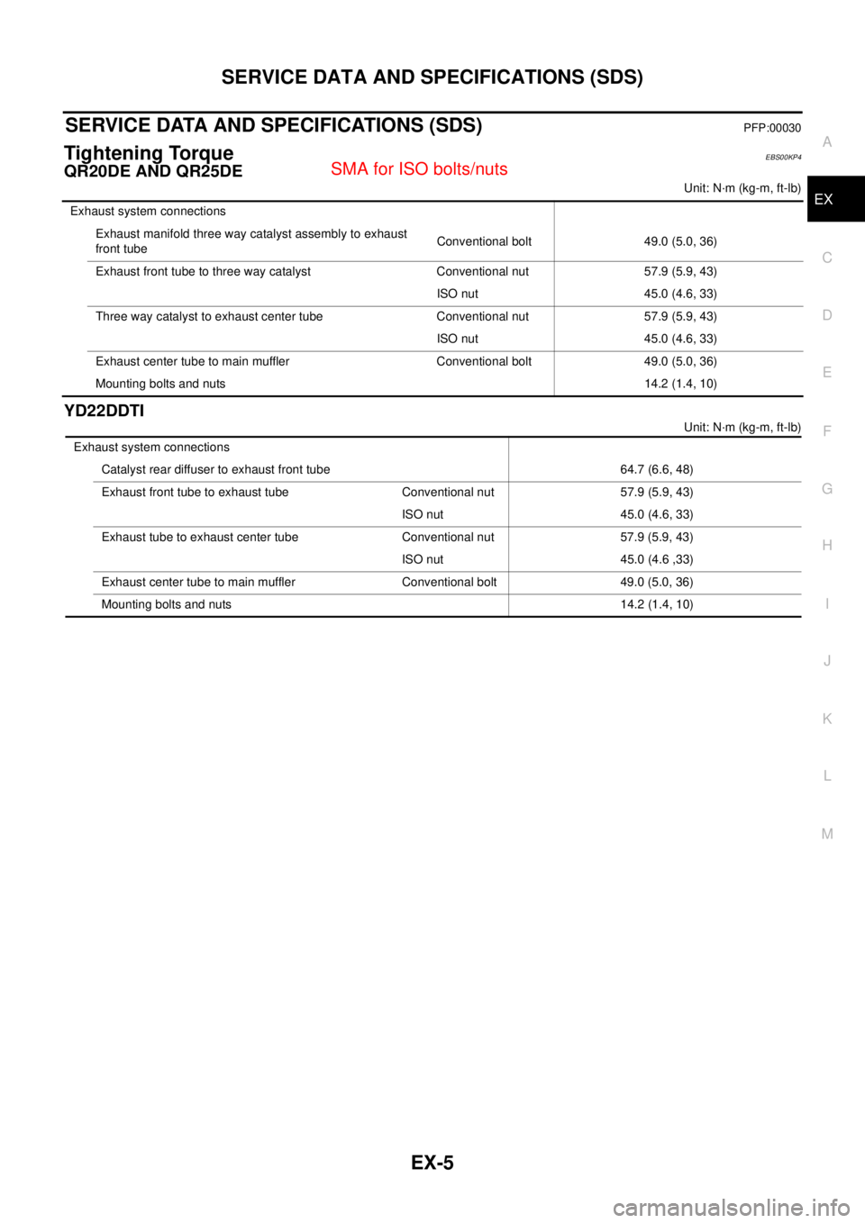
Tightening TorqueEBS00KP4
QR20DE AND QR25DE
Unit: N·m (kg-m, ft-lb)
YD22DDTI
Unit: N·m (kg-m, ft-lb) Exhaust system connections
Exhaust manifold three way catalyst assembly to exhaust
front tube Conventional bolt 49.0 (5.0, 36)
Exhaust front tube to three way catalyst Conventional nut 57.9 (5.9, 43)
ISO nut 45.0 (4.6, 33)
Three way catalyst to exhaust center tube Conventional nut 57.9 (5.9, 43)
ISO nut 45.0 (4.6, 33)
Exhaust center tube to main muffler Conventional bolt 49.0 (5.0, 36)
Mounting bolts and nuts14.2 (1.4, 10)
Exhaust system connections
Catalyst rear diffuser to exhaust front tube 64.7 (6.6, 48)
Exhaust front tube to exhaust tube Conventional nut 57.9 (5.9, 43)
ISO nut 45.0 (4.6, 33)
Exhaust tube to exhaust center tube Conventional nut 57.9 (5.9, 43)
ISO nut 45.0 (4.6 ,33)
Exhaust center tube to main muffler Conventional bolt 49.0 (5.0, 36)
Mounting bolts and nuts 14.2 (1.4, 10)
Page 3187 of 4555
PRECAUTIONS
ATC-9
C
D
E
F
G
H
I
K
L
MA
B
AT C
CAUTION:
When replacing or cleaning refrigerant cycle components, observe the following.
�When the compressor is removed, store it in the same position as it is when mounted on the car.
Malfunction to do so will cause lubricant to enter the low-pressure chamber.
�When connecting tubes, always use a torque wrench and a back-up wrench.
�After disconnecting tubes, immediately plug all openings to prevent entry of dirt and moisture.
�When installing an air conditioner in the vehicle, connect the pipes as the final stage of the opera-
tion. Do not remove the seal caps of pipes and other components until just before required for
connection.
�Allow components stored in cool areas to warm to working area temperature before removing seal
caps. This prevents condensation from forming inside A/C components.
�Thoroughly remove moisture from the refrigeration system before charging the refrigerant.
�Always replace used O-rings.
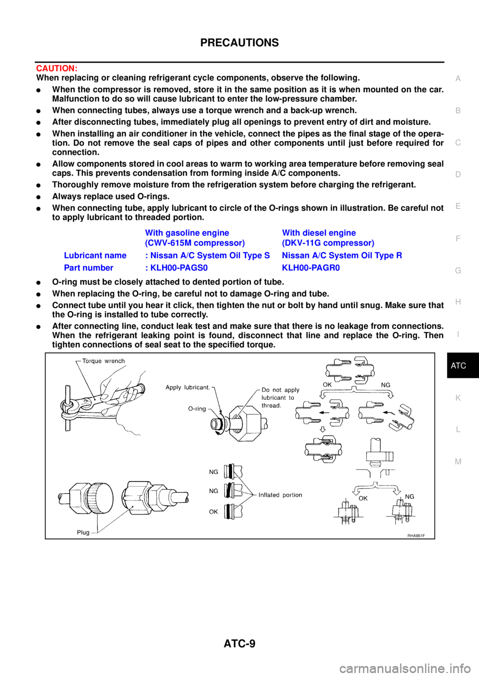
�When connecting tube, apply lubricant to circle of the O-rings shown in illustration. Be careful not
to apply lubricant to threaded portion.
�O-ring must be closely attached to dented portion of tube.
�When replacing the O-ring, be careful not to damage O-ring and tube.
�Connect tube until you hear it click, then tighten the nut or bolt by hand until snug. Make sure that
the O-ring is installed to tube correctly.
�After connecting line, conduct leak test and make sure that there is no leakage from connections.
When the refrigerant leaking point is found, disconnect that line and replace the O-ring. Then
tighten connections of seal seat to the specified torque.With gasoline engine
(CWV-615M compressor)With diesel engine
(DKV-11G compressor)
Lubricant name : Nissan A/C System Oil Type S Nissan A/C System Oil Type R
Part number : KLH00-PAGS0 KLH00-PAGR0
RHA861F
Page 3329 of 4555
REFRIGERANT LINES
ATC-151
C
D
E
F
G
H
I
K
L
MA
B
AT C
4. Install clutch disc on drive shaft, together with original shim(s).
Press clutch disc down by hand.
5. Using the holder to prevent clutch disc rotation.
After tightening the bolt, check that the pulley rotates smoothly.
6. Check clearance around the entire periphery of clutch disc.
If the specified clearance is not obtained, replace adjusting
spacer and readjust.
With Diesel Engine (DKV-11G Compressor)
1. Install field coil.
Be sure to align the coil’s pin with the hole in the compressor’s
front head.
2. Install field coil harness clip using a screwdriver.
RHA127F
Tightening torque : 14 N·m (1.4 kg-m, 10 ft-lb)
RHA086E
Disc to pulley clear-
ance: 0.3 - 0.6 mm (0.012 - 0.024 in)
RHA087E
RHA076C
Page 3330 of 4555
ATC-152
REFRIGERANT LINES
3. Install pulley assembly using installer and a hand press, and
then install snap ring using snap ring pliers.
4. Install drive plate on drive shaft, together with original shim(s).
Press clutch disc down by hand.
5. Using the holder to prevent clutch disc rotation.
After tightening the bolt, check that the pulley rotates smoothly.
ZHA094H
RHA078C
Tightening torque : 14 N·m (1.4 kg-m, 10 ft-lb)
SHA101EA
Page 3331 of 4555
REFRIGERANT LINES
ATC-153
C
D
E
F
G
H
I
K
L
MA
B
AT C
6. Check clearance around the entire periphery of clutch disc.
If the specified clearance is not obtained, replace adjusting
spacer and readjust.
Break-In Operation
When replacing compressor clutch assembly, always carry out the break-in operation. This is done by engag-
ing and disengaging the clutch about thirty times. Break-in operation raises the level of transmitted torque.
Removal and Installation of Low-pressure Flexible HoseEJS000VB
REMOVAL
1. Use a refrigerant collecting equipment (for HFC-134a) to discharge the refrigerant.
2. Remove extension cowl top panel.
3. Remove clips from low-pressure flexible hose.
4. Remove mounting bolts from low-pressure flexible hose bracket.
5. Remove harness bracket mounting bolt (With QR engine).Disc to pulley clear-
ance: 0.2 - 0.5 mm (0.008 - 0.020 in)
RHA080CA
RJIA3177E
RJIA0584E
Page 3334 of 4555
ATC-156
REFRIGERANT LINES
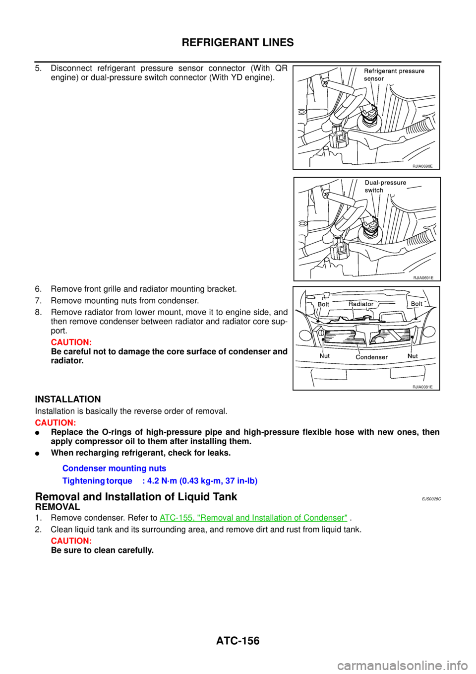
5. Disconnect refrigerant pressure sensor connector (With QR
engine) or dual-pressure switch connector (With YD engine).
6. Remove front grille and radiator mounting bracket.
7. Remove mounting nuts from condenser.
8. Remove radiator from lower mount, move it to engine side, and
then remove condenser between radiator and radiator core sup-
port.
CAUTION:
Be careful not to damage the core surface of condenser and
radiator.
INSTALLATION
Installation is basically the reverse order of removal.
CAUTION:
�Replace the O-rings of high-pressure pipe and high-pressure flexible hose with new ones, then
apply compressor oil to them after installing them.
�When recharging refrigerant, check for leaks.
Removal and Installation of Liquid TankEJS0028C
REMOVAL
1. Remove condenser. Refer to ATC-155, "Removal and Installation of Condenser" .
2. Clean liquid tank and its surrounding area, and remove dirt and rust from liquid tank.
CAUTION:
Be sure to clean carefully.
RJIA0690E
RJIA0691E
RJIA0081E
Condenser mounting nuts
Tightening torque : 4.2 N·m (0.43 kg-m, 37 in-lb)
Page 3336 of 4555
ATC-158
REFRIGERANT LINES
Removal and Installation of Dual-pressure SwitchEJS00289
REMOVAL
1. Use a refrigerant collecting equipment (for HFC-134a) to discharge the refrigerant.
2. Remove liquid tank. Refer to ATC-156, "
Removal and Installation of Liquid Tank" .
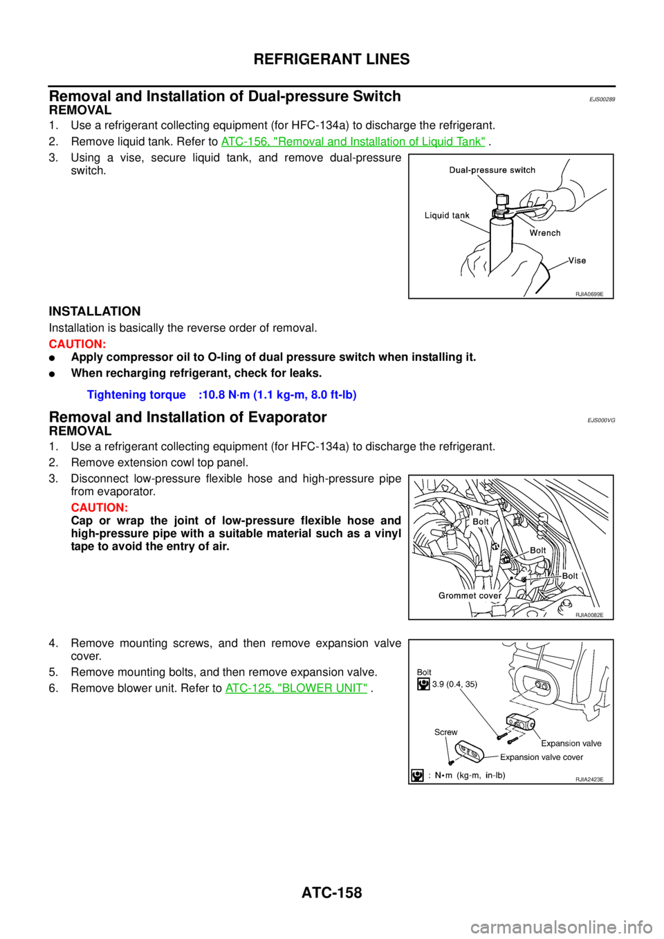
3. Using a vise, secure liquid tank, and remove dual-pressure
switch.
INSTALLATION
Installation is basically the reverse order of removal.
CAUTION:
�Apply compressor oil to O-ling of dual pressure switch when installing it.
�When recharging refrigerant, check for leaks.
Removal and Installation of EvaporatorEJS000VG
REMOVAL
1. Use a refrigerant collecting equipment (for HFC-134a) to discharge the refrigerant.
2. Remove extension cowl top panel.
3. Disconnect low-pressure flexible hose and high-pressure pipe
from evaporator.
CAUTION:
Cap or wrap the joint of low-pressure flexible hose and
high-pressure pipe with a suitable material such as a vinyl
tape to avoid the entry of air.
4. Remove mounting screws, and then remove expansion valve
cover.
5. Remove mounting bolts, and then remove expansion valve.
6. Remove blower unit. Refer to ATC-125, "
BLOWER UNIT" .
RJIA0699E
Tightening torque :10.8 N·m (1.1 kg-m, 8.0 ft-lb)
RJIA0082E
RJIA2423E