Page 3170 of 4555
BRC-122
[ESP/TCS/ABS]
STEERING ANGLE SENSOR
STEERING ANGLE SENSORPFP:25554
Removal and InstallationEFS004HA
REMOVAL
1. Remove spiral cable assembly. Refer to SRS-33, "SPIRAL CABLE" .
2. Remove steering angle sensor from spiral cable assembly.
INSTALLATION
Install in the reverse order of removal.
NOTE:
After work, make sure to adjust neutral position of steering angle sensor. Refer to BRC-52, "
Adjustment of
Steering Angle Sensor Neutral Position" .
SFIA1404E
Page 3194 of 4555
ATC-16
PREPARATION
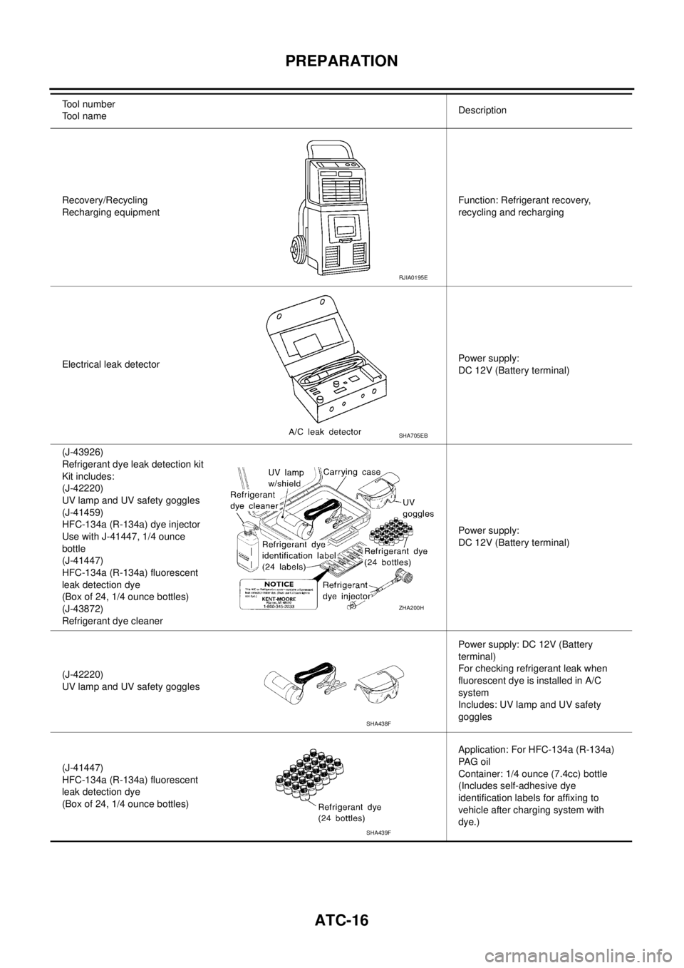
Recovery/Recycling
Recharging equipmentFunction: Refrigerant recovery,
recycling and recharging
Electrical leak detectorPower supply:
DC 12V (Battery terminal)
(J-43926)
Refrigerant dye leak detection kit
Kit includes:
(J-42220)
UV lamp and UV safety goggles
(J-41459)
HFC-134a (R-134a) dye injector
Use with J-41447, 1/4 ounce
bottle
(J-41447)
HFC-134a (R-134a) fluorescent
leak detection dye
(Box of 24, 1/4 ounce bottles)
(J-43872)
Refrigerant dye cleanerPower supply:
DC 12V (Battery terminal)
(J-42220)
UV lamp and UV safety gogglesPower supply: DC 12V (Battery
terminal)
For checking refrigerant leak when
fluorescent dye is installed in A/C
system
Includes: UV lamp and UV safety
goggles
(J-41447)
HFC-134a (R-134a) fluorescent
leak detection dye
(Box of 24, 1/4 ounce bottles)Application: For HFC-134a (R-134a)
PA G o i l
Container: 1/4 ounce (7.4cc) bottle
(Includes self-adhesive dye
identification labels for affixing to
vehicle after charging system with
dye.) Tool number
Tool nameDescription
RJIA0195E
SHA705EB
ZHA200H
SHA438F
SHA439F
Page 3198 of 4555
ATC-20
REFRIGERATION SYSTEM
DESCRIPTION
General
The variable compressor is basically a swash plate type that changes piston stroke in response to the required
cooling capacity.
The tilt of the wobble (swash) plate allows the piston’s stroke to change so that refrigerant discharge can be
continuously changed from 13.5 to 146 cm
3 (0.824 to 8.91 cu in).
SJIA0631E
Page 3199 of 4555
REFRIGERATION SYSTEM
ATC-21
C
D
E
F
G
H
I
K
L
MA
B
AT C
Operation
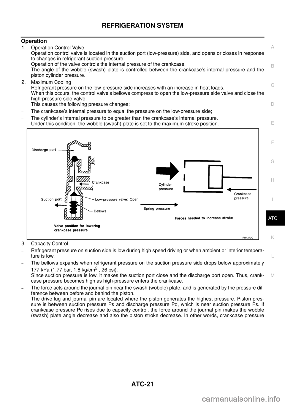
1. Operation Control Valve
Operation control valve is located in the suction port (low-pressure) side, and opens or closes in response
to changes in refrigerant suction pressure.
Operation of the valve controls the internal pressure of the crankcase.
The angle of the wobble (swash) plate is controlled between the crankcase’s internal pressure and the
piston cylinder pressure.
2. Maximum Cooling
Refrigerant pressure on the low-pressure side increases with an increase in heat loads.
When this occurs, the control valve’s bellows compress to open the low-pressure side valve and close the
high-pressure side valve.
This causes the following pressure changes:
–The crankcase’s internal pressure to equal the pressure on the low-pressure side;
–The cylinder’s internal pressure to be greater than the crankcase’s internal pressure.
Under this condition, the wobble (swash) plate is set to the maximum stroke position.
3. Capacity Control
–Refrigerant pressure on suction side is low during high speed driving or when ambient or interior tempera-
ture is low.
–The bellows expands when refrigerant pressure on the suction pressure side drops below approximately
177 kPa (1.77 bar, 1.8 kg/cm
2 , 26 psi).
Since suction pressure is low, it makes the suction port close and the discharge port open. Thus, crank-
case pressure becomes high as high-pressure enters the crankcase.
–The force acts around the journal pin near the swash (wobble) plate, and is generated by the pressure dif-
ference between before and behind the piston.
The drive lug and journal pin are located where the piston generates the highest pressure. Piston pres-
sure is between suction pressure Ps and discharge pressure Pd, which is near suction pressure Ps. If
crankcase pressure Pc rises due to capacity control, the force around the journal pin makes the wobble
(swash) plate angle decrease and also the piston stroke decrease. In other words, crankcase pressure
RHA473C
Page 3205 of 4555
AIR CONDITIONER CONTROL
ATC-27
C
D
E
F
G
H
I
K
L
MA
B
AT C
AIR CONDITIONER CONTROLPFP:27500
Description of Air Conditioner LAN Control SystemEJS000TI
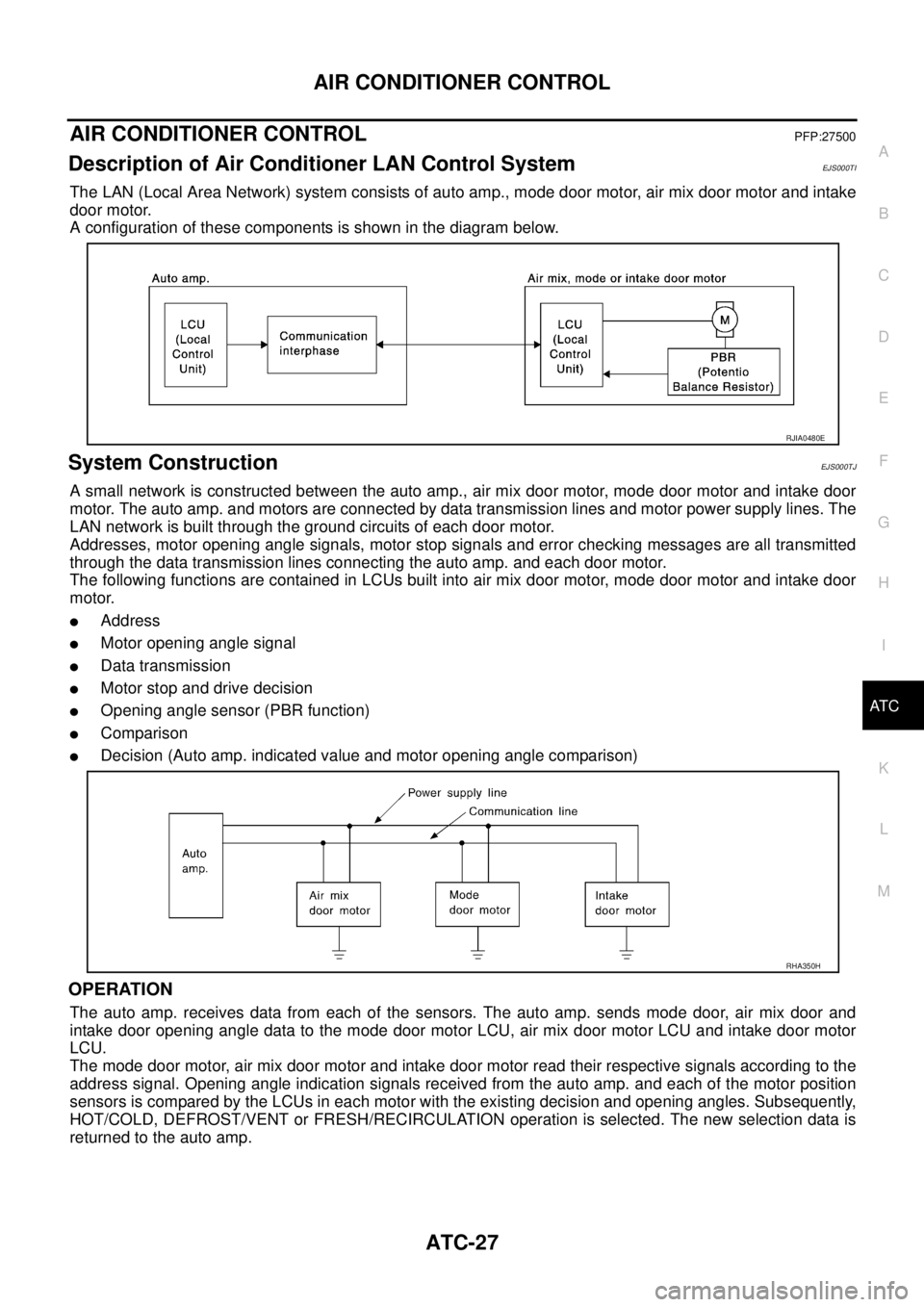
The LAN (Local Area Network) system consists of auto amp., mode door motor, air mix door motor and intake
door motor.
A configuration of these components is shown in the diagram below.
System ConstructionEJS000TJ
A small network is constructed between the auto amp., air mix door motor, mode door motor and intake door
motor. The auto amp. and motors are connected by data transmission lines and motor power supply lines. The
LAN network is built through the ground circuits of each door motor.
Addresses, motor opening angle signals, motor stop signals and error checking messages are all transmitted
through the data transmission lines connecting the auto amp. and each door motor.
The following functions are contained in LCUs built into air mix door motor, mode door motor and intake door
motor.
�Address
�Motor opening angle signal
�Data transmission
�Motor stop and drive decision
�Opening angle sensor (PBR function)
�Comparison
�Decision (Auto amp. indicated value and motor opening angle comparison)
OPERATION
The auto amp. receives data from each of the sensors. The auto amp. sends mode door, air mix door and
intake door opening angle data to the mode door motor LCU, air mix door motor LCU and intake door motor
LCU.
The mode door motor, air mix door motor and intake door motor read their respective signals according to the
address signal. Opening angle indication signals received from the auto amp. and each of the motor position
sensors is compared by the LCUs in each motor with the existing decision and opening angles. Subsequently,
HOT/COLD, DEFROST/VENT or FRESH/RECIRCULATION operation is selected. The new selection data is
returned to the auto amp.
RJIA0480E
RHA350H
Page 3240 of 4555
ATC-62
TROUBLE DIAGNOSIS
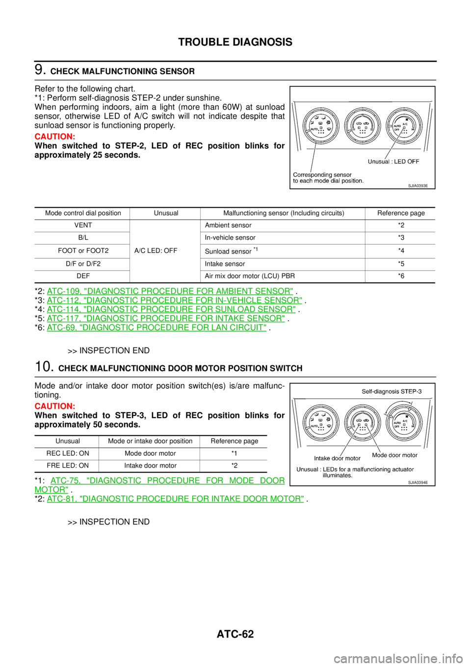
9. CHECK MALFUNCTIONING SENSOR
Refer to the following chart.
*1: Perform self-diagnosis STEP-2 under sunshine.
When performing indoors, aim a light (more than 60W) at sunload
sensor, otherwise LED of A/C switch will not indicate despite that
sunload sensor is functioning properly.
CAUTION:
When switched to STEP-2, LED of REC position blinks for
approximately 25 seconds.
*2: ATC-109, "
DIAGNOSTIC PROCEDURE FOR AMBIENT SENSOR" .
*3: AT C - 11 2 , "
DIAGNOSTIC PROCEDURE FOR IN-VEHICLE SENSOR" .
*4: AT C - 11 4 , "
DIAGNOSTIC PROCEDURE FOR SUNLOAD SENSOR" .
*5: AT C - 11 7 , "
DIAGNOSTIC PROCEDURE FOR INTAKE SENSOR" .
*6: AT C - 6 9 , "
DIAGNOSTIC PROCEDURE FOR LAN CIRCUIT" .
>> INSPECTION END
10. CHECK MALFUNCTIONING DOOR MOTOR POSITION SWITCH
Mode and/or intake door motor position switch(es) is/are malfunc-
tioning.
CAUTION:
When switched to STEP-3, LED of REC position blinks for
approximately 50 seconds.
*1: AT C - 7 5 , "
DIAGNOSTIC PROCEDURE FOR MODE DOOR
MOTOR" .
*2: AT C - 8 1 , "
DIAGNOSTIC PROCEDURE FOR INTAKE DOOR MOTOR" .
>> INSPECTION END
SJIA0393E
Mode control dial position Unusual Malfunctioning sensor (Including circuits) Reference page
VENT
A/C LED: OFFAmbient sensor *2
B/L In-vehicle sensor *3
FOOT or FOOT2
Sunload sensor
*1*4
D/F or D/F2 Intake sensor *5
DEF Air mix door motor (LCU) PBR *6
Unusual Mode or intake door position Reference page
REC LED: ON Mode door motor *1
FRE LED: ON Intake door motor *2
SJIA0394E
Page 3252 of 4555
ATC-74
TROUBLE DIAGNOSIS
SYSTEM DESCRIPTION
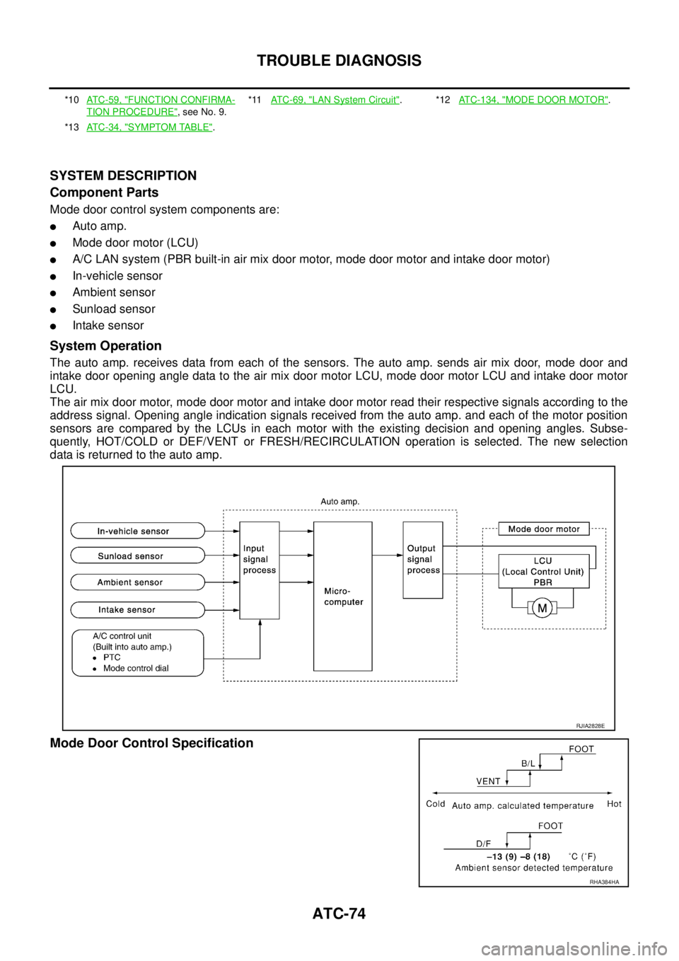
Component Parts
Mode door control system components are:
�Auto amp.
�Mode door motor (LCU)
�A/C LAN system (PBR built-in air mix door motor, mode door motor and intake door motor)
�In-vehicle sensor
�Ambient sensor
�Sunload sensor
�Intake sensor
System Operation
The auto amp. receives data from each of the sensors. The auto amp. sends air mix door, mode door and
intake door opening angle data to the air mix door motor LCU, mode door motor LCU and intake door motor
LCU.
The air mix door motor, mode door motor and intake door motor read their respective signals according to the
address signal. Opening angle indication signals received from the auto amp. and each of the motor position
sensors are compared by the LCUs in each motor with the existing decision and opening angles. Subse-
quently, HOT/COLD or DEF/VENT or FRESH/RECIRCULATION operation is selected. The new selection
data is returned to the auto amp.
Mode Door Control Specification
*10ATC-59, "FUNCTION CONFIRMA-
TION PROCEDURE", see No. 9.*11AT C - 6 9 , "
LAN System Circuit".*12ATC-134, "MODE DOOR MOTOR".
*13ATC-34, "
SYMPTOM TABLE".
RJIA2828E
RHA384HA
Page 3255 of 4555
TROUBLE DIAGNOSIS
ATC-77
C
D
E
F
G
H
I
K
L
MA
B
AT C
SYSTEM DESCRIPTION
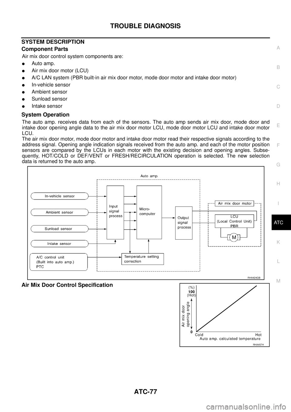
Component Parts
Air mix door control system components are:
�Auto amp.
�Air mix door motor (LCU)
�A/C LAN system (PBR built-in air mix door motor, mode door motor and intake door motor)
�In-vehicle sensor
�Ambient sensor
�Sunload sensor
�Intake sensor
System Operation
The auto amp. receives data from each of the sensors. The auto amp sends air mix door, mode door and
intake door opening angle data to the air mix door motor LCU, mode door motor LCU and intake door motor
LCU.
The air mix door motor, mode door motor and intake door motor read their respective signals according to the
address signal. Opening angle indication signals received from the auto amp. and each of the motor position
sensors are compared by the LCUs in each motor with the existing decision and opening angles. Subse-
quently, HOT/COLD or DEF/VENT or FRESH/RECIRCULATION operation is selected. The new selection
data is returned to the auto amp.
Air Mix Door Control Specification
RHA424GB
RHA457H