Page 2714 of 4555
AT-450
[ALL]
REPAIR FOR COMPONENT PARTS
3. Remove O-rings from solenoid valves and terminal body.
4. Place control valve upper body facedown, and remove bolts b ,
and nut f .
CAUTION:
Remove bolts with control valve upper body facing down,
because control valve upper body and control valve inter
body may come off and steel ball may fall and be lost.
5. Remove control valve lower body from control valve inter body.
6. Turn over control valve lower body.
7. Remove bolts e , separating plate and support plates from con-
trol valve lower body.
8. Remove check balls and oil cooler relief valve springs from con-
trol valve lower body.
CAUTION:
Be careful not to lose check balls and oil cooler relief valve
springs.
SCIA3693E
SCIA4437E
SCIA4975E
SCIA5637E
SAT110DA
Page 2716 of 4555
![NISSAN X-TRAIL 2005 Service Repair Manual AT-452
[ALL]
REPAIR FOR COMPONENT PARTS
�Check to see that retainer plates are properly positioned in con-
trol valve upper body.
Oil Strainer
�Check wire netting of oil strainer for damage.
Shift S](/manual-img/5/57403/w960_57403-2715.png "NISSAN X-TRAIL 2005 Service Repair Manual AT-452
[ALL]
REPAIR FOR COMPONENT PARTS
�Check to see that retainer plates are properly positioned in con-
trol valve upper body.
Oil Strainer
�Check wire netting of oil strainer for damage.
Shift S")
AT-452
[ALL]
REPAIR FOR COMPONENT PARTS
�Check to see that retainer plates are properly positioned in con-
trol valve upper body.
Oil Strainer
�Check wire netting of oil strainer for damage.
Shift Solenoid Valves “A” and “B”, Line Pressure Solenoid Valve, Torque Converter Clutch
Solenoid Valve and Overrun Clutch Solenoid Valve
�Measure resistance.
�Except for EURO-OBD:
�For shift solenoid valve A, refer to AT- 3 5 0 , "SHIFT SOLENOID
VALVE A" .
�For shift solenoid valve B, refer to AT- 3 5 6 , "SHIFT SOLENOID
VALVE B" .
�For line pressure solenoid valve, refer to AT- 3 8 7 , "LINE PRES-
SURE SOLENOID VALVE" .
�For torque converter clutch solenoid valve, refer to AT- 3 6 8 ,
"TORQUE CONVERTER CLUTCH SOLENOID VALVE" .
�For overrun clutch solenoid valve, refer to AT- 3 6 2 , "OVERRUN
CLUTCH SOLENOID VALVE" .
�For A/T fluid temperature sensor, refer toAT-374, "BATT/FLUID TEMP SEN (A/T FLUID TEMP SENSOR
CIRCUIT AND TCM POWER SOURCE)" .
�EURO-OBD:
�For shift solenoid valve A, refer to AT- 1 6 1 , "DTC P0750 SHIFT SOLENOID VALVE A" .
�For shift solenoid valve B, refer to AT- 1 6 7 , "DTC P0755 SHIFT SOLENOID VALVE B" .
�For line pressure solenoid valve, refer to AT- 1 5 4 , "DTC P0745 LINE PRESSURE SOLENOID VALVE" .
�For torque converter clutch solenoid valve, refer to AT- 1 4 8 , "DTC P0740 TORQUE CONVERTER
CLUTCH SOLENOID VALVE" .
�For overrun clutch solenoid valve, refer to AT- 1 7 8 , "DTC P1760 OVERRUN CLUTCH SOLENOID VALVE"
.
�For A/T fluid temperature sensor, refer to AT- 1 8 4 , "DTC BATT/FLUID TEMP SEN (A/T FLUID TEMP SEN-
SOR CIRCUIT AND TCM POWER SOURCE)" .
SCIA4979E
SCIA3291E
SCIA0805E
Page 2717 of 4555
REPAIR FOR COMPONENT PARTS
AT-453
[ALL]
D
E
F
G
H
I
J
K
L
MA
B
AT
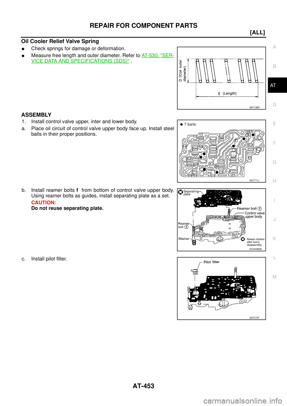
Oil Cooler Relief Valve Spring
�Check springs for damage or deformation.
�Measure free length and outer diameter. Refer to AT- 5 3 0 , "SER-
VICE DATA AND SPECIFICATIONS (SDS)" .
ASSEMBLY
1. Install control valve upper, inter and lower body.
a. Place oil circuit of control valve upper body face up. Install steel
balls in their proper positions.
b. Install reamer bolts f from bottom of control valve upper body.
Using reamer bolts as guides, install separating plate as a set.
CAUTION:
Do not reuse separating plate.
c. Install pilot filter.
SAT138D
SAT771J
SCIA4980E
SAT074F
Page 2718 of 4555
AT-454
[ALL]
REPAIR FOR COMPONENT PARTS
d. Place control valve inter body as shown in the figure (side of
control valve lower body face up). Install steel balls in their
proper positions.
e. Install control valve inter body on control valve upper body using
reamer bolts f as guides.
CAUTION:
Be careful not to dislocate or drop steel balls.
f. Install check balls and oil cooler relief valve springs in their
proper positions in control valve lower body.
g. Install bolts e from bottom of control valve lower body. Using
bolts e as guides, install separating plate as a set.
CAUTION:
Do not reuse separating plate.
h. Install support plates on control valve lower body.
i. Install control valve lower body on control valve inter body using
reamer bolts f as guides and tighten reamer bolts f slightly.
SAT705J
SCIA4981E
SAT110DA
SCIA4982E
SCIA5669E
Page 2728 of 4555
AT-464
[ALL]
REPAIR FOR COMPONENT PARTS
Reverse ClutchECS00EC4
COMPONENTS
DISASSEMBLY
1. Check operation of reverse clutch
a. Install seal ring onto drum support of oil pump cover and install
reverse clutch assembly. Apply compressed air to oil hole.
b. Check to see that retaining plate moves to snap ring.
c. If retaining plate does not contact snap ring:
�D-ring might be damaged.
�Seal ring might be damaged.
�Fluid might be leaking past piston check ball.
2. Remove snap ring.
3. Remove drive plates, driven plates, retaining plate, and dish
plates.
1. Reverse clutch drum 2. D-ring 3. Seal ring
4. Reverse clutch piston 5. Return spring 6. Spring retainer
7. Snap ring 8. Dish plate 9. Driven plate
10. Retaining plate 11. Snap ring 12. Drive plate
SCIA3889E
SAT092F
SCIA5639E
Page 2729 of 4555
![NISSAN X-TRAIL 2005 Service Repair Manual REPAIR FOR COMPONENT PARTS
AT-465
[ALL]
D
E
F
G
H
I
J
K
L
MA
B
AT
4. Set SST on spring retainer and remove snap ring from reverse
clutch drum while compressing return spring.
CAUTION:
�Set SST direc](/manual-img/5/57403/w960_57403-2728.png "NISSAN X-TRAIL 2005 Service Repair Manual REPAIR FOR COMPONENT PARTS
AT-465
[ALL]
D
E
F
G
H
I
J
K
L
MA
B
AT
4. Set SST on spring retainer and remove snap ring from reverse
clutch drum while compressing return spring.
CAUTION:
�Set SST direc")
REPAIR FOR COMPONENT PARTS
AT-465
[ALL]
D
E
F
G
H
I
J
K
L
MA
B
AT
4. Set SST on spring retainer and remove snap ring from reverse
clutch drum while compressing return spring.
CAUTION:
�Set SST directly over return spring.
�Do not expand snap ring excessively.
5. Remove spring retainer and return springs.
6. Remove reverse clutch piston from reverse clutch drum by turn-
ing it.
7. Remove D-ring and seal ring from reverse clutch piston.
INSPECTION
Reverse Clutch Snap Rings, Spring Retainer and Return Spring
�Check for deformation, fatigue or damage.
If necessary, replace.
Reverse Clutch Drive Plates
�Check facing for burns, cracks or damage.
�Measure the thickness of facing.
�If not within wear limit, replace.
Reverse Clutch Dish Plates
�Check for deformation or damage.
�Measure the thickness of dish plate.
�If deformed or fatigued, replace.
Reverse Clutch Piston
�Make sure that check balls are not fixed.
�Apply compressed air to check ball oil hole opposite the return spring. Make sure there is no air leakage.
SAT094FC
SAT096F
Thickness of drive plate:
Standard value: 1.6 mm (0.063 in)
Wear limit: 1.4 mm (0.055 in)
SAT162D
Thickness of dish plate: 3.08 mm (0.1213 in)
SAT163D
Page 2733 of 4555
REPAIR FOR COMPONENT PARTS
AT-469
[ALL]
D
E
F
G
H
I
J
K
L
MA
B
AT
High ClutchECS00EC5
COMPONENTS
DISASSEMBLY
1. Check operation of high clutch.
a. Apply compressed air to oil hole of input shaft assembly (high
clutch drum) with nylon cloth.
CAUTION:
Stop up hole on opposite side of input shaft assembly (high
clutch drum) with nylon cloth.
b. Check to see that retaining plate moves to snap ring.
c. If retaining plate does not contact snap ring:
�Fluid might be leaking past piston check ball.
2. Remove seal rings from input shaft assembly (high clutch drum).
CAUTION:
Always replace seal rings when removed.
1. Seal ring 2. Driven plate 3. Retaining plate
4. Snap ring 5. Drive plate 6. Snap ring
7. Cancel cover 8. D-ring 9. D-ring
10. Return spring 11. High clutch piston 12. Input shaft assembly (High clutch
drum)
SCIA2951E
SAT176D
SCIA4890E
Page 2735 of 4555
![NISSAN X-TRAIL 2005 Service Repair Manual REPAIR FOR COMPONENT PARTS
AT-471
[ALL]
D
E
F
G
H
I
J
K
L
MA
B
AT
High Clutch Drive Plates
�Check facing for burns, cracks or damage.
�Measure the thickness of facing.
�If not within wear limit, rep](/manual-img/5/57403/w960_57403-2734.png "NISSAN X-TRAIL 2005 Service Repair Manual REPAIR FOR COMPONENT PARTS
AT-471
[ALL]
D
E
F
G
H
I
J
K
L
MA
B
AT
High Clutch Drive Plates
�Check facing for burns, cracks or damage.
�Measure the thickness of facing.
�If not within wear limit, rep")
REPAIR FOR COMPONENT PARTS
AT-471
[ALL]
D
E
F
G
H
I
J
K
L
MA
B
AT
High Clutch Drive Plates
�Check facing for burns, cracks or damage.
�Measure the thickness of facing.
�If not within wear limit, replace.
High Clutch Piston
�Make sure that check balls are not fixed.
�Apply compressed air to check ball oil hole opposite return
spring. Make sure there is no air leakage.
�Apply compressed air to oil hole on return spring side to make
sure that air leaks past ball.
Seal Ring Clearance
�Install new seal rings onto input shaft assembly (high clutch
drum).
�Measure the clearance between seal ring and ring groove.
�If not within allowable limit, replace input shaft assembly.
ASSEMBLY
1. Install D-rings on high clutch piston.
CAUTION:
�Apply ATF to D-rings.
�Do not reuse D-rings.Thickness of drive plate:
Standard value 1.6 mm (0.063 in)
Wear limit 1.4 mm (0.055 in)
SAT162D
SAT186D
Standard clearance: 0.08 - 0.23 mm (0.0031 - 0.0091 in)
Allowable limit: 0.23 mm (0.0091 in)
SCIA4442E
SCIA4441E
![NISSAN X-TRAIL 2005 Service Repair Manual AT-450
[ALL]
REPAIR FOR COMPONENT PARTS
3. Remove O-rings from solenoid valves and terminal body.
4. Place control valve upper body facedown, and remove bolts b ,
and nut f .
CAUTION:
Remove bolts w](/manual-img/5/57403/w960_57403-2713.png "NISSAN X-TRAIL 2005 Service Repair Manual AT-450
[ALL]
REPAIR FOR COMPONENT PARTS
3. Remove O-rings from solenoid valves and terminal body.
4. Place control valve upper body facedown, and remove bolts b ,
and nut f .
CAUTION:
Remove bolts w")
![NISSAN X-TRAIL 2005 Service Repair Manual AT-454
[ALL]
REPAIR FOR COMPONENT PARTS
d. Place control valve inter body as shown in the figure (side of
control valve lower body face up). Install steel balls in their
proper positions.
e. Install](/manual-img/5/57403/w960_57403-2717.png "NISSAN X-TRAIL 2005 Service Repair Manual AT-454
[ALL]
REPAIR FOR COMPONENT PARTS
d. Place control valve inter body as shown in the figure (side of
control valve lower body face up). Install steel balls in their
proper positions.
e. Install")
![NISSAN X-TRAIL 2005 Service Repair Manual AT-464
[ALL]
REPAIR FOR COMPONENT PARTS
Reverse ClutchECS00EC4
COMPONENTS
DISASSEMBLY
1. Check operation of reverse clutch
a. Install seal ring onto drum support of oil pump cover and install
revers](/manual-img/5/57403/w960_57403-2727.png "NISSAN X-TRAIL 2005 Service Repair Manual AT-464
[ALL]
REPAIR FOR COMPONENT PARTS
Reverse ClutchECS00EC4
COMPONENTS
DISASSEMBLY
1. Check operation of reverse clutch
a. Install seal ring onto drum support of oil pump cover and install
revers")
![NISSAN X-TRAIL 2005 Service Repair Manual REPAIR FOR COMPONENT PARTS
AT-469
[ALL]
D
E
F
G
H
I
J
K
L
MA
B
AT
High ClutchECS00EC5
COMPONENTS
DISASSEMBLY
1. Check operation of high clutch.
a. Apply compressed air to oil hole of input shaft ass](/manual-img/5/57403/w960_57403-2732.png "NISSAN X-TRAIL 2005 Service Repair Manual REPAIR FOR COMPONENT PARTS
AT-469
[ALL]
D
E
F
G
H
I
J
K
L
MA
B
AT
High ClutchECS00EC5
COMPONENTS
DISASSEMBLY
1. Check operation of high clutch.
a. Apply compressed air to oil hole of input shaft ass")