Page 2671 of 4555
![NISSAN X-TRAIL 2005 Service Repair Manual ON-VEHICLE SERVICE
AT-407
[ALL]
D
E
F
G
H
I
J
K
L
MA
B
AT
11. Blow air into the oil hole as shown in the figure and remove
servo release accumulator piston from transaxle case.
CAUTION:
�Strong flow](/manual-img/5/57403/w960_57403-2670.png "NISSAN X-TRAIL 2005 Service Repair Manual ON-VEHICLE SERVICE
AT-407
[ALL]
D
E
F
G
H
I
J
K
L
MA
B
AT
11. Blow air into the oil hole as shown in the figure and remove
servo release accumulator piston from transaxle case.
CAUTION:
�Strong flow")
ON-VEHICLE SERVICE
AT-407
[ALL]
D
E
F
G
H
I
J
K
L
MA
B
AT
11. Blow air into the oil hole as shown in the figure and remove
servo release accumulator piston from transaxle case.
CAUTION:
�Strong flow of air will push the accumulator piston out
along with a splash of oil. Cover the area with paper tow-
els and blow air little by little to avoid this.
�Wrap the removed accumulator piston in a paper towel.
12. Remove O-ring from servo release accumulator piston.
13. Blow air into the oil hole shown in the figure and remove N-D
accumulator piston and return spring from transaxle case.
CAUTION:
�Strong flow of air will push the accumulator piston out
along with a splash of oil. Cover the area with paper tow-
els and blow air little by little to avoid this.
�Wrap the removed accumulator piston in a paper towel.
14. Remove O-ring from N-D accumulator piston.
15. Remove lip seals from oil groove for band servo.
INSTALLATION
�Note the following, and install in the reverse order of removal.
�Set manual shaft in Neutral position, then align manual
plate with groove in manual valve.
�After installing control valve assembly to transaxle case,
make sure that selector lever can be moved to all positions.
�After completing installation, check for leakage, and fluid
level. Refer to AT- 1 6 , "
Checking A/T Fluid".
CAUTION:
�Do not reuse O-ring and lip seal.
�Do not reuse oil pan gasket and oil pan fixing bolt.
SAT019DA
SAT020D
SAT497H
Page 2675 of 4555
ON-VEHICLE SERVICE
AT-411
[ALL]
D
E
F
G
H
I
J
K
L
MA
B
AT
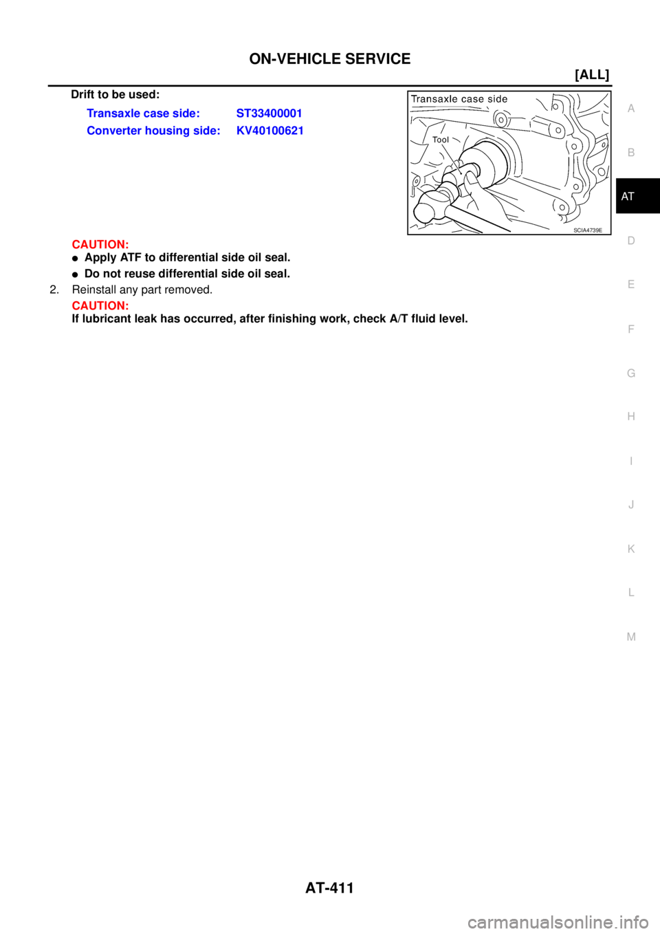
Drift to be used:
CAUTION:
�Apply ATF to differential side oil seal.
�Do not reuse differential side oil seal.
2. Reinstall any part removed.
CAUTION:
If lubricant leak has occurred, after finishing work, check A/T fluid level.Transaxle case side: ST33400001
Converter housing side: KV40100621
SCIA4739E
Page 2689 of 4555
![NISSAN X-TRAIL 2005 Service Repair Manual DISASSEMBLY
AT-425
[ALL]
D
E
F
G
H
I
J
K
L
MA
B
AT
4. Set manual shaft to position P.
5. Remove park/neutral position (PNP) switch.
6. Remove bracket from transaxle case.
7. Remove revolution sensor](/manual-img/5/57403/w960_57403-2688.png "NISSAN X-TRAIL 2005 Service Repair Manual DISASSEMBLY
AT-425
[ALL]
D
E
F
G
H
I
J
K
L
MA
B
AT
4. Set manual shaft to position P.
5. Remove park/neutral position (PNP) switch.
6. Remove bracket from transaxle case.
7. Remove revolution sensor")
DISASSEMBLY
AT-425
[ALL]
D
E
F
G
H
I
J
K
L
MA
B
AT
4. Set manual shaft to position P.
5. Remove park/neutral position (PNP) switch.
6. Remove bracket from transaxle case.
7. Remove revolution sensor from transaxle case.
8. Remove O-ring from revolution sensor.
9. Remove oil pan and oil pan gasket.
�Do not reuse oil pan bolts.
10. Check foreign materials in oil pan to help determine causes of
malfunction. If the fluid is very dark, smells burned, or contains
foreign particles, the frictional material (clutches, band) may
need replacement. A tacky film that will not wipe clean indicates
varnish build up. Varnish can cause valves, servo, and clutches
to stick and can inhibit pump pressure.
�If frictional material is detected, replace radiator after
repair of A/T. Refer to CO-12, "
RADIATOR" .
11. Remove magnets from oil pan.
12. Remove control valve assembly according to the following procedures.
a. Remove snap ring from terminal body.
b. Push terminal body into transaxle case and draw out terminal
cord assembly.
SCIA3154E
SCIA3476E
SCIA4866E
SCIA0801E
Page 2691 of 4555
![NISSAN X-TRAIL 2005 Service Repair Manual DISASSEMBLY
AT-427
[ALL]
D
E
F
G
H
I
J
K
L
MA
B
AT
16. Remove servo release accumulator piston with compressed air.
CAUTION:
�Strong flow of air will push the accumulator piston out
along with a spl](/manual-img/5/57403/w960_57403-2690.png "NISSAN X-TRAIL 2005 Service Repair Manual DISASSEMBLY
AT-427
[ALL]
D
E
F
G
H
I
J
K
L
MA
B
AT
16. Remove servo release accumulator piston with compressed air.
CAUTION:
�Strong flow of air will push the accumulator piston out
along with a spl")
DISASSEMBLY
AT-427
[ALL]
D
E
F
G
H
I
J
K
L
MA
B
AT
16. Remove servo release accumulator piston with compressed air.
CAUTION:
�Strong flow of air will push the accumulator piston out
along with a splash of oil.Cover the area with paper tow-
els and blow air little by little to avoid this.
�Wrap the removed accumulator piston in a paper towel.
17. Remove O-rings from servo release accumulator piston.
18. Remove N-D accumulator piston and return spring with com-
pressed air.
CAUTION:
�Strong flow of air will push the accumulator piston out
along with a splash of oil.Cover the area with paper tow-
els and blow air little by little to avoid this.
�Wrap the removed accumulator piston in a paper towel.
19. Remove O-rings from N-D accumulator piston.
20. Check accumulator pistons and contact surface of transaxle
case for damage.
21. Check accumulator return springs for damage and free length.
22. Remove lip seals.
23. Remove low & reverse brake tube and oil sleeve.
SAT019DA
SAT020D
SAT023DA
SCIA4867E
SCIA3478E
Page 2703 of 4555
DISASSEMBLY
AT-439
[ALL]
D
E
F
G
H
I
J
K
L
MA
B
AT
45. Remove return spring and parking pawl spacer with flat-bladed
screwdriver from parking shaft.
46. Draw out parking shaft and remove parking pawl from transaxle
case.
47. Check parking pawl and shaft for damage or wear.
48. Remove parking actuator support from transaxle case.
49. Check parking actuator support for damage or wear.
50. Remove LH differential side oil seal with flat-bladed screwdriver
from transaxle case.
CAUTION:
Be careful not to scratch transaxle case.
SCIA4881E
SAT066D
SAT040F
Page 2705 of 4555
REPAIR FOR COMPONENT PARTS
AT-441
[ALL]
D
E
F
G
H
I
J
K
L
MA
B
AT
3. Drive and pull out parking rod plate retaining pin.
4. Remove parking rod plate (with parking rod) from manual shaft.
5. Draw out parking rod (with parking rod plate) from transaxle
case.
6. Remove parking rod from parking rod plate.
7. Pull out manual shaft retaining pin.
8. Remove manual shaft and manual plate from transaxle case.
9. Remove manual shaft oil seal.
CAUTION:
Be careful not to scratch transaxle case.
INSPECTION
�Check component parts for wear or damage. Replace if necessary.
INSTALLATION
1. Use a drift [commercial service tool φ 22 mm (0.87 in)] to drive
manual shaft oil seal into the transaxle case.
CAUTION:
�Do not reuse manual shaft oil seal.
�Apply ATF to outer surface of manual shaft oil seal.
2. Install parking rod to parking rod plate.
SAT043FC
SAT049F
SAT080D
SAT081D
Page 2709 of 4555
![NISSAN X-TRAIL 2005 Service Repair Manual REPAIR FOR COMPONENT PARTS
AT-445
[ALL]
D
E
F
G
H
I
J
K
L
MA
B
AT
INSPECTION
Oil Pump Housing, Oil Pump Cover, Inner Gear and Outer Gear
�Check for wear or damage.
Side Clearances
�Measure the side](/manual-img/5/57403/w960_57403-2708.png "NISSAN X-TRAIL 2005 Service Repair Manual REPAIR FOR COMPONENT PARTS
AT-445
[ALL]
D
E
F
G
H
I
J
K
L
MA
B
AT
INSPECTION
Oil Pump Housing, Oil Pump Cover, Inner Gear and Outer Gear
�Check for wear or damage.
Side Clearances
�Measure the side")
REPAIR FOR COMPONENT PARTS
AT-445
[ALL]
D
E
F
G
H
I
J
K
L
MA
B
AT
INSPECTION
Oil Pump Housing, Oil Pump Cover, Inner Gear and Outer Gear
�Check for wear or damage.
Side Clearances
�Measure the side clearance of inner and outer gears in at least
four places around each outside edge. Maximum measured val-
ues should be within specified positions.
�If the clearance is less than standard, select inner and outer
gear as a set so that clearance is within specifications. Refer to
AT- 5 3 0 , "
SERVICE DATA AND SPECIFICATIONS (SDS)" .
�If the clearance is more than standard, replace whole oil pump
assembly except oil pump cover.
�Measure the clearance between outer gear and oil pump hous-
ing.
�If not within allowable limit, replace whole oil pump assembly
except oil pump cover.
Seal Ring Clearance
�Measure the clearance between seal ring and ring groove.
�If not within allowable limit, replace oil pump cover assembly.Standard clearance: 0.030 - 0.050 mm (0.0012 - 0.0020 in)
SAT095D
Standard clearance: 0.111 - 0.181 mm (0.0044 - 0.0071 in)
Allowable limit: 0.181 mm (0.0071 in)
SAT096D
Standard clearance: 0.1 - 0.25 mm (0.0039 - 0.0098 in)
Allowable limit: 0.25 mm (0.0098 in)
SAT097D
Page 2712 of 4555
AT-448
[ALL]
REPAIR FOR COMPONENT PARTS
Control Valve AssemblyECS00EC1
COMPONENTS
1. Oil strainer 2. O-ring 3. Snap ring
4. Terminal body 5. O-ring 6. Solenoid valve assembly
7. Control valve lower body 8. Oil cooler relief valve spring 9. Check ball
10. Separating plate 11. Support plate 12. Steel ball
13. Control valve inter body 14. Pilot filter 15. Separating plate
16. Steel ball 17. Control valve upper body
SCIA4973E
![NISSAN X-TRAIL 2005 Service Repair Manual DISASSEMBLY
AT-439
[ALL]
D
E
F
G
H
I
J
K
L
MA
B
AT
45. Remove return spring and parking pawl spacer with flat-bladed
screwdriver from parking shaft.
46. Draw out parking shaft and remove parking paw](/manual-img/5/57403/w960_57403-2702.png "NISSAN X-TRAIL 2005 Service Repair Manual DISASSEMBLY
AT-439
[ALL]
D
E
F
G
H
I
J
K
L
MA
B
AT
45. Remove return spring and parking pawl spacer with flat-bladed
screwdriver from parking shaft.
46. Draw out parking shaft and remove parking paw")
![NISSAN X-TRAIL 2005 Service Repair Manual REPAIR FOR COMPONENT PARTS
AT-441
[ALL]
D
E
F
G
H
I
J
K
L
MA
B
AT
3. Drive and pull out parking rod plate retaining pin.
4. Remove parking rod plate (with parking rod) from manual shaft.
5. Draw out](/manual-img/5/57403/w960_57403-2704.png "NISSAN X-TRAIL 2005 Service Repair Manual REPAIR FOR COMPONENT PARTS
AT-441
[ALL]
D
E
F
G
H
I
J
K
L
MA
B
AT
3. Drive and pull out parking rod plate retaining pin.
4. Remove parking rod plate (with parking rod) from manual shaft.
5. Draw out")
![NISSAN X-TRAIL 2005 Service Repair Manual AT-448
[ALL]
REPAIR FOR COMPONENT PARTS
Control Valve AssemblyECS00EC1
COMPONENTS
1. Oil strainer 2. O-ring 3. Snap ring
4. Terminal body 5. O-ring 6. Solenoid valve assembly
7. Control valve lower](/manual-img/5/57403/w960_57403-2711.png "NISSAN X-TRAIL 2005 Service Repair Manual AT-448
[ALL]
REPAIR FOR COMPONENT PARTS
Control Valve AssemblyECS00EC1
COMPONENTS
1. Oil strainer 2. O-ring 3. Snap ring
4. Terminal body 5. O-ring 6. Solenoid valve assembly
7. Control valve lower")