Page 2739 of 4555
REPAIR FOR COMPONENT PARTS
AT-475
[ALL]
D
E
F
G
H
I
J
K
L
MA
B
AT
Forward and Overrun ClutchesECS00EC6
COMPONENTS
DISASSEMBLY
1. Check operation of forward clutch and overrun clutch.
a. Install bearing retainer on forward clutch drum.
b. Apply compressed air to oil hole of forward clutch drum.
c. Check to see that retaining plate moves to snap ring.
d. If retaining plate does not contact snap ring:
�D-ring might be damaged.
�Seal ring might be damaged.
�Fluid might be leaking past piston check ball.
1. Driven plate 2. Snap ring 3. Dish plate
4. Driven plate 5. Retaining plate 6. Retaining plate
7. Snap ring 8. Drive plate 9. Forward clutch
10. Retaining plate 11. Drive plate 12. Overrun clutch
13. Dish plate 14. Spring retainer 15. Snap ring
16. Return spring 17. Overrun clutch piston 18. D-ring
19. Seal ring 20. Forward clutch piston 21. D-ring
22. Seal ring 23. Forward clutch drum
SCIA3892E
SAT123F
Page 2741 of 4555
![NISSAN X-TRAIL 2005 Service Repair Manual REPAIR FOR COMPONENT PARTS
AT-477
[ALL]
D
E
F
G
H
I
J
K
L
MA
B
AT
10. Remove D-rings and seal rings from forward clutch piston and
overrun clutch piston.
INSPECTION
Snap Rings, Spring Retainer and R](/manual-img/5/57403/w960_57403-2740.png "NISSAN X-TRAIL 2005 Service Repair Manual REPAIR FOR COMPONENT PARTS
AT-477
[ALL]
D
E
F
G
H
I
J
K
L
MA
B
AT
10. Remove D-rings and seal rings from forward clutch piston and
overrun clutch piston.
INSPECTION
Snap Rings, Spring Retainer and R")
REPAIR FOR COMPONENT PARTS
AT-477
[ALL]
D
E
F
G
H
I
J
K
L
MA
B
AT
10. Remove D-rings and seal rings from forward clutch piston and
overrun clutch piston.
INSPECTION
Snap Rings, Spring Retainer and Return Springs
�Check for deformation, fatigue or damage.
�Replace if necessary.
�When replacing spring retainer and return springs, replace them as a set.
Forward Clutch and Overrun Clutch Drive Plates
�Check facing for burns, cracks or damage.
�Measure the thickness of facing.
�If not within wear limit, replace.
Forward Clutch and Overrun Clutch Dish Plates
�Check for deformation or damage.
�Measure the thickness of dish plate.
�If deformed or fatigued, replace.
Forward Clutch Drum
�Make sure that check balls are not fixed.
�Apply compressed air to check ball oil hole from the outside of
forward clutch drum. Make sure air leaks past ball.
�Apply compressed air to oil hole from the inside of forward
clutch drum. Make sure there is no air leakage.
SCIA3046E
Thickness of drive plate:
Forward clutch
Standard value: 1.6 mm (0.063 in)
Wear limit: 1.4 mm (0.055 in)
Overrun clutch
Standard value: 1.6 mm (0.063 in)
Wear limit: 1.4 mm (0.055 in)
SAT162D
Thickness of dish plate:
Forward clutch 2.7 mm (0.106 in)
Overrun clutch 2.7 mm (0.106 in)
SAT163D
SAT213D
Page 2742 of 4555
AT-478
[ALL]
REPAIR FOR COMPONENT PARTS
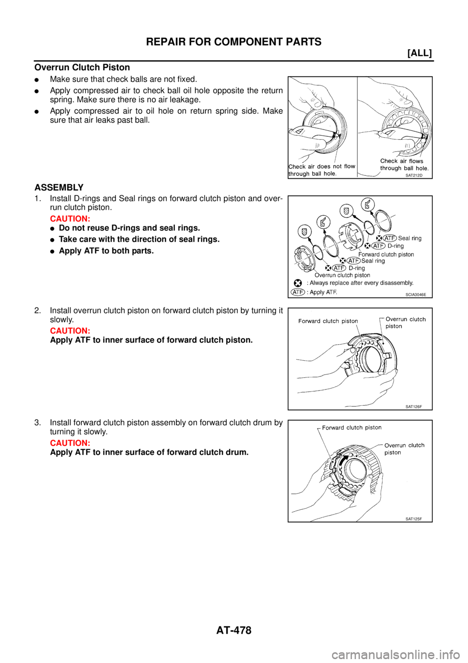
Overrun Clutch Piston
�Make sure that check balls are not fixed.
�Apply compressed air to check ball oil hole opposite the return
spring. Make sure there is no air leakage.
�Apply compressed air to oil hole on return spring side. Make
sure that air leaks past ball.
ASSEMBLY
1. Install D-rings and Seal rings on forward clutch piston and over-
run clutch piston.
CAUTION:
�Do not reuse D-rings and seal rings.
�Take care with the direction of seal rings.
�Apply ATF to both parts.
2. Install overrun clutch piston on forward clutch piston by turning it
slowly.
CAUTION:
Apply ATF to inner surface of forward clutch piston.
3. Install forward clutch piston assembly on forward clutch drum by
turning it slowly.
CAUTION:
Apply ATF to inner surface of forward clutch drum.
SAT212D
SCIA3046E
SAT126F
SAT125F
Page 2747 of 4555
REPAIR FOR COMPONENT PARTS
AT-483
[ALL]
D
E
F
G
H
I
J
K
L
MA
B
AT
Low & Reverse BrakeECS00EC7
COMPONENTS
DISASSEMBLY
1. Check operation of low & reverse brake.
a. Apply compressed air to oil hole of transaxle case.
b. Check to see that retaining plate moves to snap ring.
c. If retaining plate does not contact snap ring:
�D-ring might be damaged.
�Fluid might be leaking past piston check ball.
2. Remove snap ring with flat-bladed screwdriver.
3. Remove retainer, low & reverse brake piston and spring retainer
from transaxle case.
4. Remove snap ring with flat-bladed screwdriver.
5. Remove driven plates, drive plate, retaining plate and dish
plates on transaxle case.
1. Driven plate 2. Dish plate 3. Snap ring
4. Spring retainer 5. D-ring 6. D-ring
7. Low & reverse brake piston 8. Retainer 9. Snap ring
10. Retaining plate 11. Drive plate 12. Retaining plate
SCIA3893E
SCIA4903E
SCIA4904E
Page 2748 of 4555
AT-484
[ALL]
REPAIR FOR COMPONENT PARTS
6. In order to remove low & reverse brake piston, apply com-
pressed air to oil hole of retainer while holding low & reverse
brake piston.
CAUTION:
Apply air gradually and allow low & reverse brake piston to
come out evenly.
7. Remove D-rings from low & reverse brake piston.
INSPECTION
Low and Reverse Brake Snap Ring, Spring Retainer and Return Springs
�Check for deformation, fatigue or damage.
If necessary, replace.
�When replacing spring retainer and return springs, replace them as a set.
Low and Reverse Brake Drive Plate
�Check the facing for burns, cracks or damage.
�Measure the thickness of facing.
�If not within wear limit, replace.
ASSEMBLY
1. Install D-rings on piston.
CAUTION:
�Apply ATF to both parts.
�Do not reuse D-ring.
SCIA3651E
SCIA4381E
Thickness of drive plate:
Standard value 1.8 mm (0.071 in)
Wear limit 1.6 mm (0.063 in)
SAT162D
SCIA2998E
Page 2789 of 4555
ASSEMBLY
AT-525
[ALL]
D
E
F
G
H
I
J
K
L
MA
B
AT
9. Apply compressed air to oil holes of transaxle case and check
operation of brake band.
10. Install final drive assembly on transaxle case.
11. Install differential lubricant tube on converter housing. Tighten
differential lubricant tube bolts to the specified torque. Refer to
AT- 4 1 6 , "
Components" .
12. Install O-ring on differential oil port of transaxle case.
CAUTION:
�Do not reuse O-ring.
�Apply ATF to O-ring.
13. Install converter housing on transaxle case.
CAUTION:
Apply locking sealant (Locktite #518) to mating surface of
converter housing.
SAT397D
SAT228F
SAT063K
SCIA3281E
SCIA4929E
Page 2790 of 4555
AT-526
[ALL]
ASSEMBLY
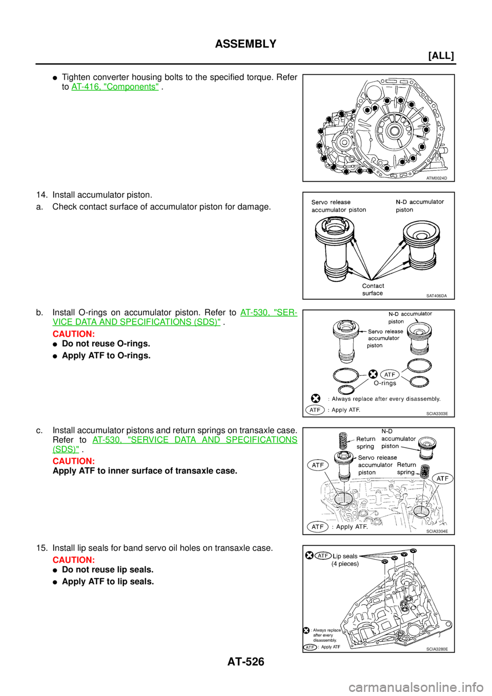
�Tighten converter housing bolts to the specified torque. Refer
to AT- 4 1 6 , "
Components" .
14. Install accumulator piston.
a. Check contact surface of accumulator piston for damage.
b. Install O-rings on accumulator piston. Refer to AT- 5 3 0 , "
SER-
VICE DATA AND SPECIFICATIONS (SDS)" .
CAUTION:
�Do not reuse O-rings.
�Apply ATF to O-rings.
c. Install accumulator pistons and return springs on transaxle case.
Refer to AT- 5 3 0 , "
SERVICE DATA AND SPECIFICATIONS
(SDS)" .
CAUTION:
Apply ATF to inner surface of transaxle case.
15. Install lip seals for band servo oil holes on transaxle case.
CAUTION:
�Do not reuse lip seals.
�Apply ATF to lip seals.
ATM0024D
SAT406DA
SCIA3303E
SCIA3304E
SCIA3280E
Page 2795 of 4555
![NISSAN X-TRAIL 2005 Service Repair Manual SERVICE DATA AND SPECIFICATIONS (SDS)
AT-531
[ALL]
D
E
F
G
H
I
J
K
L
MA
B
AT
Stall RevolutionECS00CXM
Line PressureECS00F1T
Control ValvesECS00F1U
CONTROL VALVE AND PLUG RETURN SPRINGS
For 85X23 mod](/manual-img/5/57403/w960_57403-2794.png "NISSAN X-TRAIL 2005 Service Repair Manual SERVICE DATA AND SPECIFICATIONS (SDS)
AT-531
[ALL]
D
E
F
G
H
I
J
K
L
MA
B
AT
Stall RevolutionECS00CXM
Line PressureECS00F1T
Control ValvesECS00F1U
CONTROL VALVE AND PLUG RETURN SPRINGS
For 85X23 mod")
SERVICE DATA AND SPECIFICATIONS (SDS)
AT-531
[ALL]
D
E
F
G
H
I
J
K
L
MA
B
AT
Stall RevolutionECS00CXM
Line PressureECS00F1T
Control ValvesECS00F1U
CONTROL VALVE AND PLUG RETURN SPRINGS
For 85X23 model
Unit: mm (in)
*: Always check with the Parts Department for the latest parts information.EngineStall revolution
rpm
QR20DE 2,450 - 2,950
QR25DE 2,300 - 2,750
Engine speed
rpmLine pressure kPa (kg/cm2 , psi)
D, 2 and 1 positions R position
Idle 500 (5.1, 73) 778 (7.9, 113)
Stall 1,233 (12.6, 179) 1,918 (19.6, 278)
PartsItem
Part No.* Free length Outer diameter
Upper body7 Pilot valve spring 31742-3AX03 38.98 (1.535) 8.9 (0.350)
35 1-2 accumulator valve spring 31742-3AX00 20.5 (0.807) 6.95 (0.274)
10 1-2 accumulator piston spring 31742-85X02 55.60 (2.189) 19.6 (0.772)
17 1st reducing valve spring 31742-80X05 27.0 (1.063) 7.0 (0.276)
19 3-2 timing valve spring 31736-01X00 23.0 (0.906) 6.65 (0.262)
24 Overrun clutch reducing valve spring 31742-80X15 37.5 (1.476) 6.9 (0.272)
26 Torque converter relief valve spring 31742-80X07 31.0 (1.220) 9.0 (0.354)
31 Torque converter clutch control valve 31742-85X00 56.98 (2.243) 6.5 (0.256)
3 Cooler check valve spring 31742-85X01 29.4 (1.157) 6.0 (0.236)
Lower body11 Pressure regulator valve spring 31742-80X13 45.0 (1.772) 15.0 (0.591)
16 Overrun clutch control valve spring 31762-80X00 21.7 (0.854) 7.0 (0.276)
20 Accumulator control valve spring 31742-80X02 22.0 (0.866) 6.5 (0.256)
25 Shift valve A spring 31762-80X00 21.7 (0.854) 7.0 (0.276)
30 Shuttle valve spring 31762-41X04 51.0 (2.008) 5.65 (0.222)
32 Shift valve B spring 31762-80X00 21.7 (0.854) 7.0 (0.276)
2 Pressure modifier piston spring 31742-41X15 30.5 (1.201) 9.8 (0.386)
6 Pressure modifier valve spring 31742-80X16 32.0 (1.260) 6.9 (0.272)
— Oil cooler relief valve spring 31872-31X00 17.02 (0.670) 8.0 (0.315)
![NISSAN X-TRAIL 2005 Service Repair Manual REPAIR FOR COMPONENT PARTS
AT-475
[ALL]
D
E
F
G
H
I
J
K
L
MA
B
AT
Forward and Overrun ClutchesECS00EC6
COMPONENTS
DISASSEMBLY
1. Check operation of forward clutch and overrun clutch.
a. Install bear](/manual-img/5/57403/w960_57403-2738.png "NISSAN X-TRAIL 2005 Service Repair Manual REPAIR FOR COMPONENT PARTS
AT-475
[ALL]
D
E
F
G
H
I
J
K
L
MA
B
AT
Forward and Overrun ClutchesECS00EC6
COMPONENTS
DISASSEMBLY
1. Check operation of forward clutch and overrun clutch.
a. Install bear")
![NISSAN X-TRAIL 2005 Service Repair Manual REPAIR FOR COMPONENT PARTS
AT-483
[ALL]
D
E
F
G
H
I
J
K
L
MA
B
AT
Low & Reverse BrakeECS00EC7
COMPONENTS
DISASSEMBLY
1. Check operation of low & reverse brake.
a. Apply compressed air to oil hole of](/manual-img/5/57403/w960_57403-2746.png "NISSAN X-TRAIL 2005 Service Repair Manual REPAIR FOR COMPONENT PARTS
AT-483
[ALL]
D
E
F
G
H
I
J
K
L
MA
B
AT
Low & Reverse BrakeECS00EC7
COMPONENTS
DISASSEMBLY
1. Check operation of low & reverse brake.
a. Apply compressed air to oil hole of")
![NISSAN X-TRAIL 2005 Service Repair Manual AT-484
[ALL]
REPAIR FOR COMPONENT PARTS
6. In order to remove low & reverse brake piston, apply com-
pressed air to oil hole of retainer while holding low & reverse
brake piston.
CAUTION:
Apply air](/manual-img/5/57403/w960_57403-2747.png "NISSAN X-TRAIL 2005 Service Repair Manual AT-484
[ALL]
REPAIR FOR COMPONENT PARTS
6. In order to remove low & reverse brake piston, apply com-
pressed air to oil hole of retainer while holding low & reverse
brake piston.
CAUTION:
Apply air")
![NISSAN X-TRAIL 2005 Service Repair Manual ASSEMBLY
AT-525
[ALL]
D
E
F
G
H
I
J
K
L
MA
B
AT
9. Apply compressed air to oil holes of transaxle case and check
operation of brake band.
10. Install final drive assembly on transaxle case.
11. Inst](/manual-img/5/57403/w960_57403-2788.png "NISSAN X-TRAIL 2005 Service Repair Manual ASSEMBLY
AT-525
[ALL]
D
E
F
G
H
I
J
K
L
MA
B
AT
9. Apply compressed air to oil holes of transaxle case and check
operation of brake band.
10. Install final drive assembly on transaxle case.
11. Inst")