Page 4067 of 4555

HEADLAMP AIMING CONTROL (AUTO)
LT-71
C
D
E
F
G
H
I
J
L
MA
B
LT
NOTE:
This item is displayed, but does not function.
ACTIVE TEST
Operation Procedure
1. Touch “HEAD LAMP LEVELIZER” on “SELECT SYSTEM” screen.
2. Touch “ACTIVE TEST” on “SELECT DIAG MODE” screen.
3. Touch “LAMP TEST”, then “MAX”, “MID” or “MIN” to change aiming line.
4. Touch “END” after the test.
Display Item List
SELF-DIAG RESULTS
Operation Procedure
1. Touch “SELF-DIAG RESULTS” on the “SELECT DIAG MODE” screen.
2. Check display content in self-diagnostic results.
Description of DTC and Solutions after Detection
CONSULT-II can detect DTC (Diagnosis trouble code). The descriptions and solutions of DTC are listed
below.
Item (CONSULT-II screen terms) Test item Description
LAMP TEST Aiming direction changeOperation of headlamp aiming motor can be confirmed with
“MAX”, “MID” or “MIN” touched.
Details of error
indication
detected
by CONSULT-IIConditions of
error detectionCode
storageFail-safe
Reference Within 5 seconds
after ignition switch
ON, or vehicle speed
less than or equal to
4 km/h (2.48 MPH).5 seconds and more
after ignition switch
ON, or vehicle
speed more than to
4 km/h (2.48 MPH).
[B2080]
[ECU TROUBLE]ECU error of the
height sensor.YES
�Fix headlamp aiming motor drive signal
around 0 V.
�Maintain a current position of light axis.Replace height sensor, and
initialize it. Refer to LT- 8 6 , "Removal and Installation of
Height Sensor" .
[B2081]
[INITIAL NOT DONE]Initialization has not
completed.
NO Set and maintain light axis downward.Refer to LT- 7 8 , "
DTC B2081
[INITIAL NOT DONE]" .
[B2082]
[SENSOR OUT OF
RANGE]Vehicle height
detected by height
sensor is unusual.Refer to LT- 7 9 , "
DTC B2082
[SENSOR OUT OF RANGE]"
.
Page 4069 of 4555
HEADLAMP AIMING CONTROL (AUTO)
LT-73
C
D
E
F
G
H
I
J
L
MA
B
LT
Check Aiming Control SystemEKS00N65
*1 Refer to FSU-5, "FRONT SUSPEN-
SION ASSEMBLY" i n “ F S U se c ti o n”
and RSU-5, "
REAR SUSPENSION
ASSEMBLY" in“ RSU section”.*2 Refer to LT- 8 6 , "
Removal and Instal-
lation of Height Sensor" .*3 Refer to LT-71, "
SELF-DIAG
RESULTS" .
*4 Refer to LT-71, "
Description of DTC
and Solutions after Detection" . *5 Refer to LT- 7 1 , "
ACTIVE TEST" . *6 Refer to LT-21, "Removal and Instal-
lation of Headlamp" in “HEADLAMP
-XENON TYPE-”.
PKIC0426E
Page 4070 of 4555

LT-74
HEADLAMP AIMING CONTROL (AUTO)
CAUTION:
If the vehicle height is outside the proper height, aiming control may not be performed normally even
when the headlamp aiming control system is normal.
Symptom ChartEKS00N66
Headlamp Aiming Motor Does Not Operate (Both Sides)EKS00N67
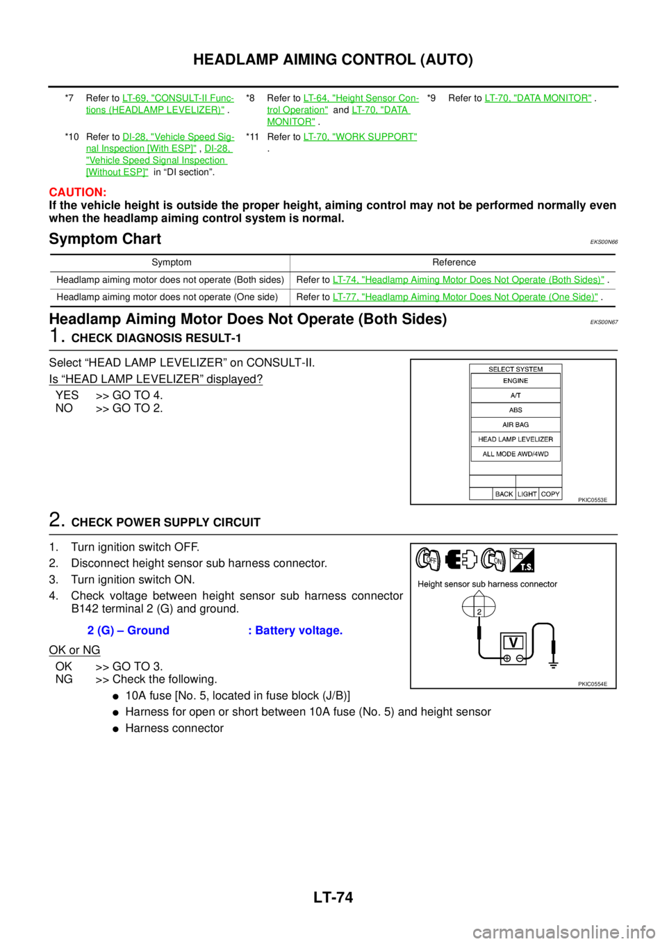
1. CHECK DIAGNOSIS RESULT-1
Select “HEAD LAMP LEVELIZER” on CONSULT-II.
Is
“HEAD LAMP LEVELIZER” displayed?
YES >> GO TO 4.
NO >> GO TO 2.
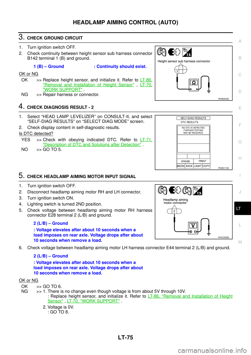
2. CHECK POWER SUPPLY CIRCUIT
1. Turn ignition switch OFF.
2. Disconnect height sensor sub harness connector.
3. Turn ignition switch ON.
4. Check voltage between height sensor sub harness connector
B142 terminal 2 (G) and ground.
OK or NG
OK >> GO TO 3.
NG >> Check the following.
�10A fuse [No. 5, located in fuse block (J/B)]
�Harness for open or short between 10A fuse (No. 5) and height sensor
�Harness connector
*7 Refer to LT- 6 9 , "CONSULT-II Func-
tions (HEADLAMP LEVELIZER)" .*8 Refer to LT-64, "
Height Sensor Con-
trol Operation" and LT- 7 0 , "DATA
MONITOR" .*9 Refer to LT- 7 0 , "
DATA MONITOR" .
*10 Refer to DI-28, "
Vehicle Speed Sig-
nal Inspection [With ESP]" , DI-28,
"Vehicle Speed Signal Inspection
[Without ESP]" in “DI section”.*11 Refer to LT-70, "
WORK SUPPORT"
.
Symptom Reference
Headlamp aiming motor does not operate (Both sides) Refer to LT- 7 4 , "
Headlamp Aiming Motor Does Not Operate (Both Sides)" .
Headlamp aiming motor does not operate (One side) Refer to LT- 7 7 , "
Headlamp Aiming Motor Does Not Operate (One Side)" .
PKIC0553E
2 (G) – Ground : Battery voltage.
PKIC0554E
Page 4071 of 4555

HEADLAMP AIMING CONTROL (AUTO)
LT-75
C
D
E
F
G
H
I
J
L
MA
B
LT
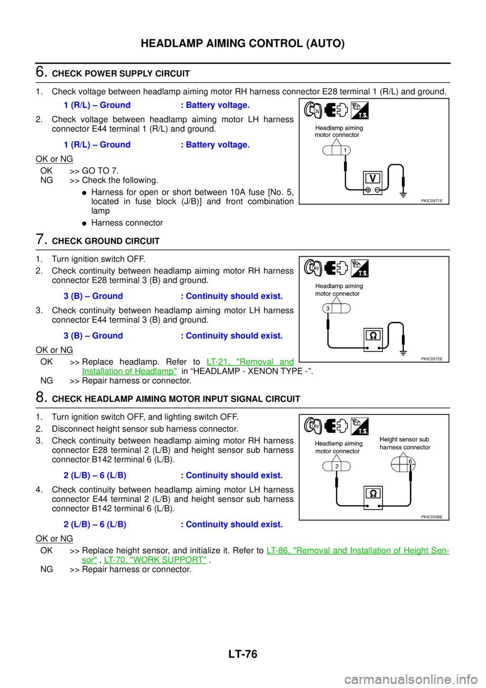
3. CHECK GROUND CIRCUIT
1. Turn ignition switch OFF.
2. Check continuity between height sensor sub harness connector
B142 terminal 1 (B) and ground.
OK or NG
OK >> Replace height sensor, and initialize it. Refer to LT- 8 6 ,
"Removal and Installation of Height Sensor" , LT- 7 0 ,
"WORK SUPPORT" .
NG >> Repair harness or connector.
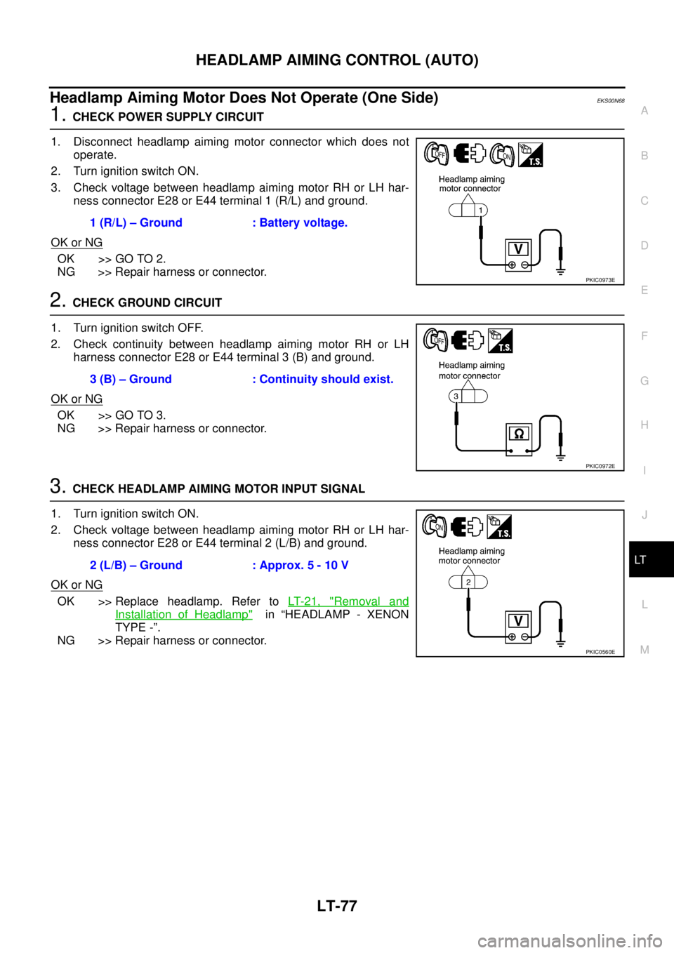
4. CHECK DIAGNOSIS RESULT - 2
1. Select “HEAD LAMP LEVELIZER” on CONSULT-II, and select
“SELF-DIAG RESULTS” on “SELECT DIAG MODE” screen.
2. Check display content in self-diagnostic results.
Is DTC detected?
YES >> Check with obeying indicated DTC. Refer to LT- 7 1 ,
"Description of DTC and Solutions after Detection" .
NO >> GO TO 5.
5. CHECK HEADLAMP AIMING MOTOR INPUT SIGNAL
1. Turn ignition switch OFF.
2. Disconnect headlamp aiming motor RH and LH connector.
3. Turn ignition switch ON.
4. Lighting switch is turned 2ND position.
5. Check voltage between headlamp aiming motor RH harness
connector E28 terminal 2 (L/B) and ground.
6. Check voltage between headlamp aiming motor LH harness connector E44 terminal 2 (L/B) and ground.
OK or NG
OK >> GO TO 6.
NG >> 1. There is no change even though voltage is from about 5V through 10V.
: Replace height sensor, and initialize it. Refer to LT- 8 6 , "
Removal and Installation of Height
Sensor" , LT- 7 0 , "WORK SUPPORT" .
2. Voltage is 0V.
: GO TO 8. 1 (B) – Ground : Continuity should exist.
PKIB9425E
PKIB0115E
2 (L/B) – Ground
: Voltage elevates after about 10 seconds when a
load imposes on rear axle. Voltage drops after about
10 seconds when remove a load.
2 (L/B) – Ground
: Voltage elevates after about 10 seconds when a
load imposes on rear axle. Voltage drops after about
10 seconds when remove a load.
PKIC0555E
Page 4072 of 4555

LT-76
HEADLAMP AIMING CONTROL (AUTO)
6. CHECK POWER SUPPLY CIRCUIT
1. Check voltage between headlamp aiming motor RH harness connector E28 terminal 1 (R/L) and ground.
2. Check voltage between headlamp aiming motor LH harness
connector E44 terminal 1 (R/L) and ground.
OK or NG
OK >> GO TO 7.
NG >> Check the following.
�Harness for open or short between 10A fuse [No. 5,
located in fuse block (J/B)] and front combination
lamp
�Harness connector
7. CHECK GROUND CIRCUIT
1. Turn ignition switch OFF.
2. Check continuity between headlamp aiming motor RH harness
connector E28 terminal 3 (B) and ground.
3. Check continuity between headlamp aiming motor LH harness
connector E44 terminal 3 (B) and ground.
OK or NG
OK >> Replace headlamp. Refer to LT- 2 1 , "Removal and
Installation of Headlamp" in “HEADLAMP - XENON TYPE -”.
NG >> Repair harness or connector.
8. CHECK HEADLAMP AIMING MOTOR INPUT SIGNAL CIRCUIT
1. Turn ignition switch OFF, and lighting switch OFF.
2. Disconnect height sensor sub harness connector.
3. Check continuity between headlamp aiming motor RH harness
connector E28 terminal 2 (L/B) and height sensor sub harness
connector B142 terminal 6 (L/B).
4. Check continuity between headlamp aiming motor LH harness
connector E44 terminal 2 (L/B) and height sensor sub harness
connector B142 terminal 6 (L/B).
OK or NG
OK >> Replace height sensor, and initialize it. Refer to LT- 8 6 , "Removal and Installation of Height Sen-
sor" , LT- 7 0 , "WORK SUPPORT" .
NG >> Repair harness or connector.1 (R/L) – Ground : Battery voltage.
1 (R/L) – Ground : Battery voltage.
PKIC0971E
3 (B) – Ground : Continuity should exist.
3 (B) – Ground : Continuity should exist.
PKIC0972E
2 (L/B) – 6 (L/B) : Continuity should exist.
2 (L/B) – 6 (L/B) : Continuity should exist.
PKIC0558E
Page 4073 of 4555

HEADLAMP AIMING CONTROL (AUTO)
LT-77
C
D
E
F
G
H
I
J
L
MA
B
LT
Headlamp Aiming Motor Does Not Operate (One Side)EKS00N68
1. CHECK POWER SUPPLY CIRCUIT
1. Disconnect headlamp aiming motor connector which does not
operate.
2. Turn ignition switch ON.
3. Check voltage between headlamp aiming motor RH or LH har-
ness connector E28 or E44 terminal 1 (R/L) and ground.
OK or NG
OK >> GO TO 2.
NG >> Repair harness or connector.
2. CHECK GROUND CIRCUIT
1. Turn ignition switch OFF.
2. Check continuity between headlamp aiming motor RH or LH
harness connector E28 or E44 terminal 3 (B) and ground.
OK or NG
OK >> GO TO 3.
NG >> Repair harness or connector.
3. CHECK HEADLAMP AIMING MOTOR INPUT SIGNAL
1. Turn ignition switch ON.
2. Check voltage between headlamp aiming motor RH or LH har-
ness connector E28 or E44 terminal 2 (L/B) and ground.
OK or NG
OK >> Replace headlamp. Refer to LT- 2 1 , "Removal and
Installation of Headlamp" in “HEADLAMP - XENON
TYPE -”.
NG >> Repair harness or connector.1 (R/L) – Ground : Battery voltage.
PKIC0973E
3 (B) – Ground : Continuity should exist.
PKIC0972E
2 (L/B) – Ground : Approx. 5 - 10 V
PKIC0560E
Page 4074 of 4555
LT-78
HEADLAMP AIMING CONTROL (AUTO)
DTC B2081 [INITIAL NOT DONE]EKS00N69
1. INITIALIZE HEIGHT SENSOR
1. Turn ignition switch OFF.
2. Set the vehicle in unladen condition. (Removal all loads in pas-
senger and trunk rooms.)
3. Turn ignition switch ON.
4. Select “HEAD LAMP LEVELIZER” on CONSULT-II, and select
“WORK SUPPORT” on “SELECT DIAG MODE” screen.
5. Select “SENSOR INITIALISE” on “SELECT WORK ITEM”
screen.
6. Touch “WRITE”.
7. When “INITIALISE COMPLETE” is indicated, touch “END”.
OK or NG
OK >> INSPECTION END
NG >>
�When “INCORRECT CONDITION” is displayed, check connect CONSULT-II and height sensor
connector, and then initialize again. Refer to LT- 7 0 , "
WORK SUPPORT" .
�When “INITIALISE NOT DONE“ is displayed, initialize again. If “ INITIALISE NOT DONE” is dis-
played again, replace height sensor and initialize it. Refer to LT- 8 6 , "
Removal and Installation of
Height Sensor" and LT- 7 0 , "WORK SUPPORT" .
PKIC0537E
Page 4075 of 4555
![NISSAN X-TRAIL 2005 Service Repair Manual HEADLAMP AIMING CONTROL (AUTO)
LT-79
C
D
E
F
G
H
I
J
L
MA
B
LT
DTC B2082 [SENSOR OUT OF RANGE]EKS00N6A
1. CHECK HEIGHT SENSOR
1. Select “HEAD LAMP LEVELIZER” on CONSULT-II and “DATA
MONITOR” NISSAN X-TRAIL 2005 Service Repair Manual HEADLAMP AIMING CONTROL (AUTO)
LT-79
C
D
E
F
G
H
I
J
L
MA
B
LT
DTC B2082 [SENSOR OUT OF RANGE]EKS00N6A
1. CHECK HEIGHT SENSOR
1. Select “HEAD LAMP LEVELIZER” on CONSULT-II and “DATA
MONITOR”](/manual-img/5/57403/w960_57403-4074.png)
HEADLAMP AIMING CONTROL (AUTO)
LT-79
C
D
E
F
G
H
I
J
L
MA
B
LT
DTC B2082 [SENSOR OUT OF RANGE]EKS00N6A
1. CHECK HEIGHT SENSOR
1. Select “HEAD LAMP LEVELIZER” on CONSULT-II and “DATA
MONITOR” on “SELECT DIAG MODE” screen.
2. Lighting switch is turned 1ST position.
3. Check “INT SEN VALUE” in unloaded condition. (Remove all
loads in the passenger and trunk room.)
OK or NG
OK >> Erase the self-diagnosis result and perform the self-
diagnosis again.
�[B2082] is displayed again: Replace height sensor, and initialize it. Refer to LT- 8 6 , "Removal
and Installation of Height Sensor" and LT- 7 0 , "WORK SUPPORT" .
�NO DTC is displayed: INSPECTION END
NG >> GO TO 2.
2. CHECK INSTALLATION CONDITION OF HEIGHT SENSOR
Check height sensor and linkage for deformation or damage.
NOTE:
[B2082] may be displayed when the vehicle is lifted up.
OK or NG
OK >> Replace height sensor, and initialize it. Refer to LT- 8 6 , "Removal and Installation of Height Sen-
sor" and LT- 7 0 , "WORK SUPPORT" .
NG >> Adjust height sensor, or replace height sensor, and initialize it. Refer to LT- 8 6 , "
Removal and
Installation of Height Sensor" and LT- 7 0 , "WORK SUPPORT" .
DTC B2083 [SEN SIG NOT PLAUSIBLE]EKS00N6B
1. CHECK HEIGHT SENSOR
1. Select “HEAD LAMP LEVELIZER” on CONSULT-II and “DATA
MONITOR” on “SELECT DIAG MODE” screen.
2. Lighting switch is turned 1ST position.
3. Check if the “INT SEN VALUE” changes as the rear height of the
vehicle changes.
OK or NG
OK >> Erase the self-diagnosis result and perform the self-
diagnosis again.
�[B2083] is displayed again: Replace height sensor, and initialize it. Refer to LT- 8 6 , "Removal
and Installation of Height Sensor" and LT- 7 0 , "WORK SUPPORT" .
�NO DTC is displayed: INSPECTION END
NG >> GO TO 2.INT SEN VALUE : Should not be approx. 0% or
approx. 100%.
PKIB7209E
INT SEN VALUE : Should vary as rear height of the
vehicle changes.
PKIB7209E