Page 4176 of 4555

DI-28
COMBINATION METERS
6. CHECK INSTALLATION CONDITION
Check fuel level sensor unit installation, and check whether the float arm interferes or binds with any of the
internal components in the fuel tank.
OK or NG
OK >> Replace combination meter.
NG >> Install fuel level sensor unit properly.
Engine Speed Signal Inspection EKS00EHD
1. CHECK ECM SELF-DIAGNOSIS
Perform ECM self-diagnosis. Refer to EC-103, "
CONSULT-II Function (ENGINE)" [QR (WITH EURO-OBD)],
EC-604, "
CONSULT-II Function (ENGINE)" [QR (WITHOUT EURO -OBD)] or EC-1034, "CONSULT-II Func-
tion (ENGINE)" [YD].
OK or NG
OK >> Replace combination meter.
NG >> Perform “Diagnostic Procedure” in displayed DTC.
Engine Coolant Temperature Signal InspectionEKS00EHE
1. CHECK ECM SELF-DIAGNOSIS
Perform ECM self-diagnosis. Refer to EC-103, "
CONSULT-II Function (ENGINE)" [QR (WITH EURO-OBD)],
EC-604, "
CONSULT-II Function (ENGINE)" [QR (WITHOUT EURO - OBD)] or EC-1034, "CONSULT-II Func-
tion (ENGINE)" [YD].
OK or NG
OK >> Replace combination meter.
NG >> Perform “Diagnostic Procedure” in displayed DTC.
Vehicle Speed Signal Inspection [With ESP]EKS00EHF
1. CHECK ESP/TCS/ABS CONTROL UNIT SELF-DIAGNOSIS
Perform ESP/TCS/ABS control unit self-diagnosis. Refer to BRC-79, "
CONSULT-II Functions" .
OK or NG
OK >> Replace combination meter.
NG >> Check applicable parts.
Vehicle Speed Signal Inspection [Without ESP]EKS00EJB
1. CHECK ABS ACTUATOR CONTROL UNIT SELF-DIAGNOSIS
Perform ABS actuator and electric unit self-diagnosis. Refer to BRC-26, "
CONSULT- II Functions" .
OK or NG
OK >> Replace combination meter.
NG >> Check applicable parts.
The Fuel Gauge Pointer Fluctuates, Indicator Wrong Value or VariesEKS00EHG
1. CHECK FUEL GAUGE FLUCTUATION
Test drive vehicle to see if gauge fluctuates only during driving or at the instant of stopping.
Does the indication value vary only during driving or at the instant of stopping?
YES >> The pointer fluctuation may be caused by fuel level change in the fuel tank. Condition is normal.
NO >> Ask the customer about the situation when the symptom occurs in detail, and perform the trouble
diagnosis.
Page 4177 of 4555
COMBINATION METERS
DI-29
C
D
E
F
G
H
I
J
L
MA
B
DI
The Fuel Gauge Does Not Move to FULL PositionEKS00EHH
1. QUESTION 1
Does it take a long time for the pointer to move to FULL position?
YES >> GO TO 2.
NO >> GO TO 3.
2. QUESTION 2
Was the vehicle fueled with the ignition switch ON?
YES >> Be sure to fuel the vehicle with the ignition switch OFF. Otherwise, it will take a long time to move
to FULL position because of the characteristic of the fuel gauge.
NO >> GO TO 3.
3. QUESTION 3
Is the vehicle parked on an incline?
YES >> Check the fuel level indication with vehicle on a level surface.
NO >> GO TO 4.
4. QUESTION 4
During driving, does the fuel gauge pointer move gradually toward EMPTY position?
YES >> Check fuel level sensor unit. Refer to DI-25, "Fuel Level Sensor Signal Inspection [Gasoline
Engine Models]" or DI-26, "Fuel Level Sensor Signal Inspection [Diesel Engine Models]" .
NO >> The float arm may interfere or bind with any of the components in the fuel tank.
Page 4178 of 4555
![NISSAN X-TRAIL 2005 Service Repair Manual DI-30
COMBINATION METERS
Ambient Temperature Signal Inspection [Without Auto A/C] EKS00EJ6
1. CHECK VOLTAGE BETWEEN AMBIENT SENSOR HARNESS CONNECTOR AND GROUND
1. Turn ignition switch OFF.
2. Discon](/manual-img/5/57403/w960_57403-4177.png "NISSAN X-TRAIL 2005 Service Repair Manual DI-30
COMBINATION METERS
Ambient Temperature Signal Inspection [Without Auto A/C] EKS00EJ6
1. CHECK VOLTAGE BETWEEN AMBIENT SENSOR HARNESS CONNECTOR AND GROUND
1. Turn ignition switch OFF.
2. Discon")
DI-30
COMBINATION METERS
Ambient Temperature Signal Inspection [Without Auto A/C] EKS00EJ6
1. CHECK VOLTAGE BETWEEN AMBIENT SENSOR HARNESS CONNECTOR AND GROUND
1. Turn ignition switch OFF.
2. Disconnect ambient sensor harness connector.
3. Turn ignition switch ON.
4. Check voltage between ambient sensor harness connector E38
terminal 1 (R/B) and ground.
OK or NG
OK >> GO TO 2.
NG >> GO TO 4.
2. CHECK AMBIENT SENSOR CIRCUIT BETWEEN AMBIENT SENSOR AND COMBINATION METER
1. Turn ignition switch OFF.
2. Disconnect combination meter connector.
3. Check continuity between combination meter harness connector
M44 terminal 28 (B/Y) and ambient sensor harness connector
E38 terminal 2 (B/Y).
OK or NG
OK >> GO TO 3.
NG >> Repair harness or connector.
3. CHECK AMBIENT SENSOR
Check ambient sensor. Refer to DI-33, "
AMBIENT SENSOR CHECK" .
OK or NG
OK >> Replace combination meter.
NG >> Replace ambient sensor.
4. CHECK AMBIENT SENSOR CIRCUIT BETWEEN AMBIENT SENSOR AND COMBINATION METER
1. Turn ignition switch OFF.
2. Disconnect combination meter connector.
3. Check continuity between combination meter harness connector
M44 terminal 27 (R/B) and ambient sensor connector E38 termi-
nal 1 (R/B).
4. Check continuity between combination meter harness connector
M44 terminal 27 (R/B) and ground.
OK or NG
OK >> Replace combination.
NG >> Repair harness or connector.Approx. 5 V
SKIA9198E
Continuity should exist.
SKIA9134E
Continuity should exist.
Continuity should not exist.
SKIA9135E
Page 4179 of 4555
![NISSAN X-TRAIL 2005 Service Repair Manual COMBINATION METERS
DI-31
C
D
E
F
G
H
I
J
L
MA
B
DI
Ambient Temperature Signal Inspection [With Auto A/C]EKS00EJ7
1. CHECK AUTO A/C RECOGNITION SIGNAL INPUT
1. Turn ignition switch OFF.
2. Disconnect](/manual-img/5/57403/w960_57403-4178.png "NISSAN X-TRAIL 2005 Service Repair Manual COMBINATION METERS
DI-31
C
D
E
F
G
H
I
J
L
MA
B
DI
Ambient Temperature Signal Inspection [With Auto A/C]EKS00EJ7
1. CHECK AUTO A/C RECOGNITION SIGNAL INPUT
1. Turn ignition switch OFF.
2. Disconnect")
COMBINATION METERS
DI-31
C
D
E
F
G
H
I
J
L
MA
B
DI
Ambient Temperature Signal Inspection [With Auto A/C]EKS00EJ7
1. CHECK AUTO A/C RECOGNITION SIGNAL INPUT
1. Turn ignition switch OFF.
2. Disconnect combination meter connector.
3. Turn ignition switch ON.
4. Check voltage between combination meter harness connector
M44 terminal 29 (Y) and ground.
OK or NG
OK >> GO TO 3.
NG >> GO TO 2.
2. CHECK AUTO A/C RECOGNITION SIGNAL CIRCUIT
1. Turn ignition switch OFF.
2. Disconnect A/C auto amp. connector.
3. Check continuity between combination meter harness connector
M44 terminal 29 (Y) and A/C auto amp. harness connector M53
terminal 28(Y).
4. Check continuity between combination meter harness connector
M44 terminal 29 (Y) and ground.
OK or NG
OK >> Replace A/C auto amp.
NG >> Repair harness or connector.
3. CHECK AMBIENT SENSOR CIRCUIT BETWEEN AMBIENT SENSOR AND COMBINATION METER
1. Turn ignition switch OFF.
2. Disconnect ambient sensor connector.
3. Check continuity between combination meter harness connector
M44 terminal 27 (R/B) and ambient sensor harness connector
E38 terminal 1 (R/B).
4. Check continuity between combination meter harness connector
M44 terminal 27 (R/B) and ground.
OK or NG
OK >> GO TO 4.
NG >> Repair harness or connector.
4. CHECK A/C AUTO AMP. CIRCUIT
Check A/C auto amp. circuit. Refer to ATC-109, "
Ambient Sensor Circuit" in ATC section.
OK or NG
OK >> Replace combination meter.
NG >> Check applicable parts, and repair or replace corresponding parts.Approx. 5 V
SKIA9136E
Continuity should exist.
Continuity should not exist.
SKIB0604E
Continuity should exist.
Continuity should not exist.
SKIA9135E
Page 4180 of 4555

DI-32
COMBINATION METERS
Electrical Components InspectionEKS00INH
FUEL LEVEL SENSOR UNIT CHECK/GASOLINE ENGINE MODELS
For removal, refer to FL-4, "FUEL LEVEL SENSOR UNIT, FUEL FILTER AND FUEL PUMP ASSEMBLY" for
Gasoline engine models.
Fuel level sensor unit
Check resistance between terminals 1 and 4.
*1 and *2: When float rod is in contact with stopper.
Sub fuel level sensor unit
Check resistance between terminals 1 and 3.
*1 and *2: When float rod is in contact with stopper.
FUEL LEVEL SENSOR UNIT CHECK/DIESEL ENGINE MODELS
For removal, refer to FL-19, "FUEL LEVEL SENSOR UNIT" for Diesel engine models.
Fuel level sensor unit
Check resistance between terminals 1 and 4.
*1 and *2: When float rod is in contact with stopper.
Sub fuel level sensor unit
Check resistance between terminals 1 and 3.
*1 and *2: When float rod is in contact with stopper.Terminal Float position [mm (in)] Resistance value [Ω]
14*1 Full 24 (0.94) Approx. 5
*2 Empty 167 (6.57) Approx. 80
SKIA0904E
Terminal Float position [mm (in)] Resistance value [Ω]
13*1 Full 35 (1.38) Approx. 1
*2 Empty 186 (7.32) Approx. 40
SKIA1032E
Terminal Float position [mm (in)] Resistance value [Ω]
14*1 Full 24 (0.94) Approx. 5
*2 Empty 170 (6.69) Approx. 80
SKIA0909E
Terminal Float position [mm (in)] Resistance value [Ω]
13*1 Full 34 (1.34) Approx. 1
*2 Empty 186 (7.32) Approx. 40
SKIA0910E
Page 4181 of 4555
COMBINATION METERS
DI-33
C
D
E
F
G
H
I
J
L
MA
B
DI
AMBIENT SENSOR CHECK
Ambient Sensor
After disconnecting ambient sensor harness connector, measure
resistance between terminals 2 and 1 at sensor harness side, using
the table below.
If NG, replace ambient sensor.
Removal and Installation for Combination MeterEKS00EHJ
REMOVAL
1. Remove cluster lid A. Refer to IP-10, "INSTRUMENT PANEL
ASSEMBLY" .
2. Remove the screws (4), and pull out combination meter.
3. Disconnect connectors and remove combination meter.
INSTALLATION
Installation is the reverse order of removal.
Temperature [°C (°F)] Resistance [kΩ]
−15 (5) 12.73
−10 (14) 9.92
−5 (23) 7.80
0 (32) 6.19
5 (41) 4.95
10 (50) 3.99
15 (59) 3.24
20 (68) 2.65
25 (77) 2.19
30 (86) 1.81
35 (95) 1.51
40 (104) 1.27
45 (113) 1.07
RJIA0684E
SKIA8927E
Page 4200 of 4555
DI-52
WARNING LAMPS
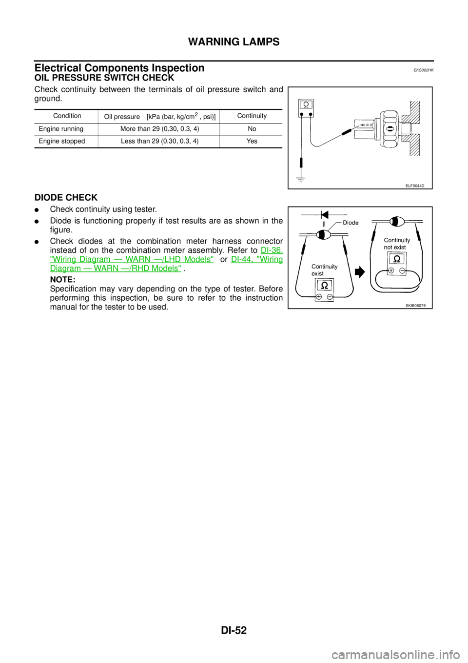
Electrical Components InspectionEKS002HK
OIL PRESSURE SWITCH CHECK
Check continuity between the terminals of oil pressure switch and
ground.
DIODE CHECK
�Check continuity using tester.
�Diode is functioning properly if test results are as shown in the
figure.
�Check diodes at the combination meter harness connector
instead of on the combination meter assembly. Refer to DI-36,
"Wiring Diagram — WARN —/LHD Models" or DI-44, "Wiring
Diagram — WARN —/RHD Models" .
NOTE:
Specification may vary depending on the type of tester. Before
performing this inspection, be sure to refer to the instruction
manual for the tester to be used.
Condition
Oil pressure [kPa (bar, kg/cm2 , psi)]Continuity
Engine running More than 29 (0.30, 0.3, 4) No
Engine stopped Less than 29 (0.30, 0.3, 4) Yes
ELF0044D
SKIB0607E
Page 4203 of 4555
A/T INDICATOR
DI-55
C
D
E
F
G
H
I
J
L
MA
B
DI
A/T Indicator Does Not IlluminateEKS00ES6
1. CHECK TCM SELF-DIAGNOSIS
Perform TCM self-diagnosis. Refer to AT- 4 0 , "
ON BOARD DIAGNOSTIC SYSTEM DESCRIPTION" [EURO-
OBD] or AT- 2 4 2 , "
ON BOARD DIAGNOSTIC SYSTEM DESCRIPTION" [EXC.F/EURO-OBD].
OK or NG
OK >> Replace combination meter.
NG >> Go to TCM trouble diagnosis.