Page 3939 of 4555
TROUBLE DIAGNOSIS
MTC-15
C
D
E
F
G
H
I
K
L
MA
B
MTC
Blower Motor CircuitEJS001FI
SYMPTOM: Blower motor operation is malfunctioning.
INSPECTION FLOW
*1MTC-16, "DIAGNOSTIC PROCE-
DURE FOR BLOWER MOTOR".*2MTC-7, "
Operational Check".*3MTC-3, "SYMPTOM TABLE".
*4MTC-7, "
Operational Check".
RJIA0601E
Page 3940 of 4555
MTC-16
TROUBLE DIAGNOSIS
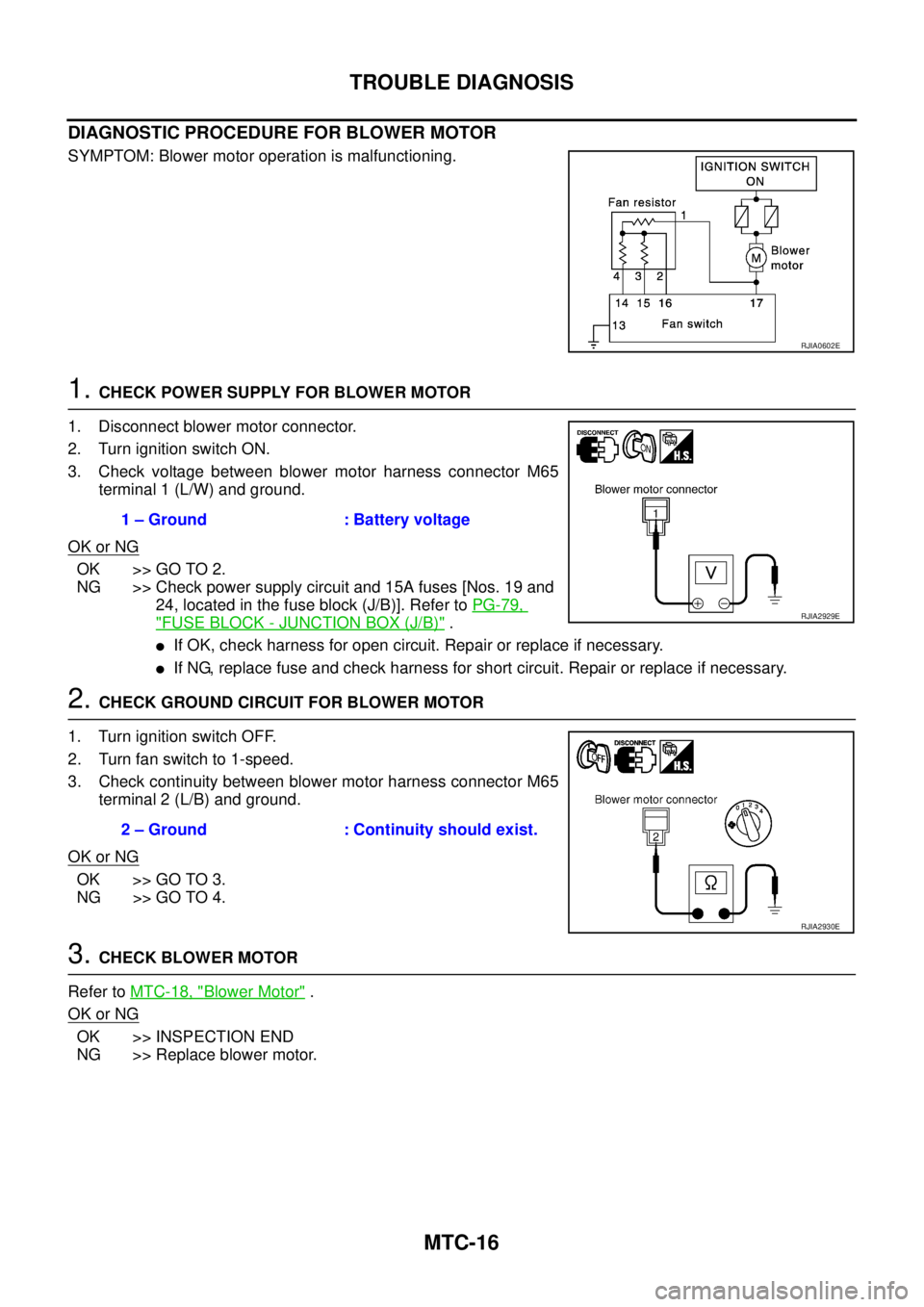
DIAGNOSTIC PROCEDURE FOR BLOWER MOTOR
SYMPTOM: Blower motor operation is malfunctioning.
1. CHECK POWER SUPPLY FOR BLOWER MOTOR
1. Disconnect blower motor connector.
2. Turn ignition switch ON.
3. Check voltage between blower motor harness connector M65
terminal 1 (L/W) and ground.
OK or NG
OK >> GO TO 2.
NG >> Check power supply circuit and 15A fuses [Nos. 19 and
24, located in the fuse block (J/B)]. Refer to PG-79,
"FUSE BLOCK - JUNCTION BOX (J/B)" .
�If OK, check harness for open circuit. Repair or replace if necessary.
�If NG, replace fuse and check harness for short circuit. Repair or replace if necessary.
2. CHECK GROUND CIRCUIT FOR BLOWER MOTOR
1. Turn ignition switch OFF.
2. Turn fan switch to 1-speed.
3. Check continuity between blower motor harness connector M65
terminal 2 (L/B) and ground.
OK or NG
OK >> GO TO 3.
NG >> GO TO 4.
3. CHECK BLOWER MOTOR
Refer to MTC-18, "
Blower Motor" .
OK or NG
OK >> INSPECTION END
NG >> Replace blower motor.
RJIA0602E
1 – Ground : Battery voltage
RJIA2929E
2 – Ground : Continuity should exist.
RJIA2930E
Page 3941 of 4555
TROUBLE DIAGNOSIS
MTC-17
C
D
E
F
G
H
I
K
L
MA
B
MTC
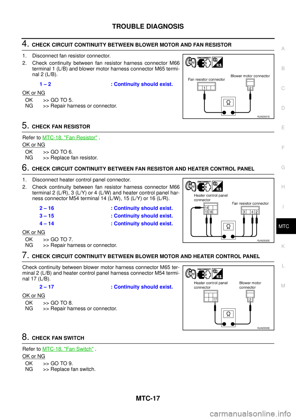
4. CHECK CIRCUIT CONTINUITY BETWEEN BLOWER MOTOR AND FAN RESISTOR
1. Disconnect fan resistor connector.
2. Check continuity between fan resistor harness connector M66
terminal 1 (L/B) and blower motor harness connector M65 termi-
nal 2 (L/B).
OK or NG
OK >> GO TO 5.
NG >> Repair harness or connector.
5. CHECK FAN RESISTOR
Refer to MTC-18, "
Fan Resistor" .
OK or NG
OK >> GO TO 6.
NG >> Replace fan resistor.
6. CHECK CIRCUIT CONTINUITY BETWEEN FAN RESISTOR AND HEATER CONTROL PANEL
1. Disconnect heater control panel connector.
2. Check continuity between fan resistor harness connector M66
terminal 2 (L/R), 3 (L/Y) or 4 (L/W) and heater control panel har-
ness connector M54 terminal 14 (L/W), 15 (L/Y) or 16 (L/R).
OK or NG
OK >> GO TO 7.
NG >> Repair harness or connector.
7. CHECK CIRCUIT CONTINUITY BETWEEN BLOWER MOTOR AND HEATER CONTROL PANEL
Check continuity between blower motor harness connector M65 ter-
minal 2 (L/B) and heater control panel harness connector M54 termi-
nal 17 (L/B).
OK or NG
OK >> GO TO 8.
NG >> Repair harness or connector.
8. CHECK FAN SWITCH
Refer to MTC-18, "
Fan Switch" .
OK or NG
OK >> GO TO 9.
NG >> Replace fan switch.1 – 2 : Continuity should exist.
RJIA2931E
2 – 16 : Continuity should exist.
3 – 15 : Continuity should exist.
4 – 14 : Continuity should exist.
RJIA2932E
2 – 17 : Continuity should exist.
RJIA2933E
Page 3942 of 4555
MTC-18
TROUBLE DIAGNOSIS
9. CHECK GROUND CIRCUIT
Check continuity between heater control panel harness connector
M54 terminal 13 (B) and ground.
OK or NG
OK >> INSPECTION END
NG >> Repair harness or connector.
COMPONENT INSPECTION
Blower Motor
Confirm smooth rotation of the blower motor.
�Ensure that there are no foreign particles inside the intake unit.
Fan Switch
Check continuity between heater control connector M54 terminals at
each switch position.
Fan Resistor
Check resistance between fan resister connector M66 terminals.13 – Ground : Continuity should exist.
RJIA2934E
RJIA0609E
Switch position Terminals Continuity
OFF 13 - 14, 15, 16, 17 No
1 13 - 14
Ye s 2 13 - 15
3 13 - 16
4 13 - 17
RJIA0610E
TerminalsResistance (Ω)
LHD RHD
12 0.25 - 0.31 0.28 - 0.34
3 0.58 - 0.70 0.79 - 0.97
4 1.33 - 1.63 1.84 - 2.24
RJIA0611E
Page 3944 of 4555
MTC-20
TROUBLE DIAGNOSIS
*1 QR engine; CO-9, "Changing Engine
Coolant" or YD engine; CO-32,
"Changing Engine Coolant" .*2 QR engine; CO-13, "
Checking Radi-
ator Cap" or YD engine; CO-36,
"Checking Radiator Cap" .*3 QR engine; (WITH EURO-OBD) EC-
165, "DTC P0117, P0118 ECT SEN-
SOR" .
QR engine; (WITHOUT EURO-OBD)
EC-652, "
DTC P0117, P0118 ECT
SENSOR" .
YD engine; (WITH EURO-OBD) EC-
1093, "DTC P0117, P0118 ECT
SENSOR" .
YD engine; (WITHOUT EURO-OBD)
EC-1449, "
DTC P0117, P0118 ECT
SENSOR" .
*4 QR engine; CO-9, "
Changing Engine
Coolant" or YD engine; CO-32,
"Changing Engine Coolant" .*5 MTC-7, "
Operational Check" .*6MTC-3, "SYMPTOM TABLE".
Page 3961 of 4555
SC-1
STARTING & CHARGING SYSTEM
K ELECTRICAL
CONTENTS
C
D
E
F
G
H
I
J
L
M
SECTION SC
A
B
SC
STARTING & CHARGING SYSTEM
PRECAUTIONS .......................................................... 2
Precautions for Supplemental Restraint System
(SRS) “AIR BAG” and “SEAT BELT PRE-TEN-
SIONER” .................................................................. 2
Wiring Diagrams and Trouble Diagnosis .................. 2
PREPARATION ........................................................... 3
Special Service Tools ............................................... 3
BATTERY .................................................................... 4
How to Handle Battery ............................................. 4
METHODS OF PREVENTING OVER-DIS-
CHARGE ............................................................... 4
CHECKING ELECTROLYTE LEVEL .................... 4
SPECIFIC GRAVITY CHECK ............................... 5
Battery Test and Charging Chart .............................. 6
CHART I ................................................................ 6
CHART II ............................................................... 7
A: SLOW CHARGE ............................................... 8
B: STANDARD CHARGE ...................................... 9
C: QUICK CHARGE ............................................. 11
Removal and Installation ........................................ 12
CHARGING SYSTEM ............................................... 13
System Description ................................................ 13
Wiring Diagram — CHARGE — /With Gasoline
Engine .................................................................... 14
Wiring Diagram — CHARGE — /With Diesel Engine ... 15
Trouble Diagnosis .................................................. 16
WITH IC REGULATOR ....................................... 16
MALFUNCTION INDICATOR .............................. 16
Removal and Installation ........................................ 17
REMOVAL (QR ENGINE MODELS) ................... 17
REMOVAL (YD ENGINE MODELS) ................... 17
ALTERNATOR PULLEY INSPECTION (QR ENGINE MODELS) ............................................. 17
INSTALLATION ................................................... 18
Disassembly and Assembly .................................... 19
DISASSEMBLY ................................................... 20
INSPECTION ...................................................... 21
ASSEMBLY ......................................................... 22
STARTING SYSTEM ................................................. 23
System Description ................................................. 23
M/T MODELS ...................................................... 23
A/T MODELS ....................................................... 23
Wiring Diagram — START — /M/T Models ............ 24
Wiring Diagram — START — /A/T Models ............. 25
Trouble Diagnosis ................................................... 26
Removal and Installation ........................................ 27
REMOVAL ........................................................... 27
INSTALLATION ................................................... 27
Disassembly and Assembly .................................... 28
QR ENGINE MODELS ........................................ 28
YD ENGINE MODELS ........................................ 30
Inspection ............................................................... 31
MAGNETIC SWITCH CHECK ............................. 31
PINION/CLUTCH CHECK ................................... 31
BRUSH CHECK .................................................. 31
YOKE CHECK ..................................................... 32
ARMATURE CHECK ........................................... 33
Assembly ................................................................ 34
PINION PROTRUSION LENGTH ADJUST-
MENT .................................................................. 34
SERVICE DATA AND SPECIFICATIONS (SDS) ...... 36
Battery .................................................................... 36
Starter ..................................................................... 36
Alternator ................................................................ 36
Page 3964 of 4555
SC-4
BATTERY
BATTERY PFP:00011
How to Handle Battery EKS00313
CAUTION:
�If it becomes necessary to start the engine with a booster battery and jumper cables, use a 12-volt
booster battery.
�After connecting battery cables, ensure that they are tightly clamped to battery terminals for good
contact.
�Never add distilled water through the hole used to check specific gravity.
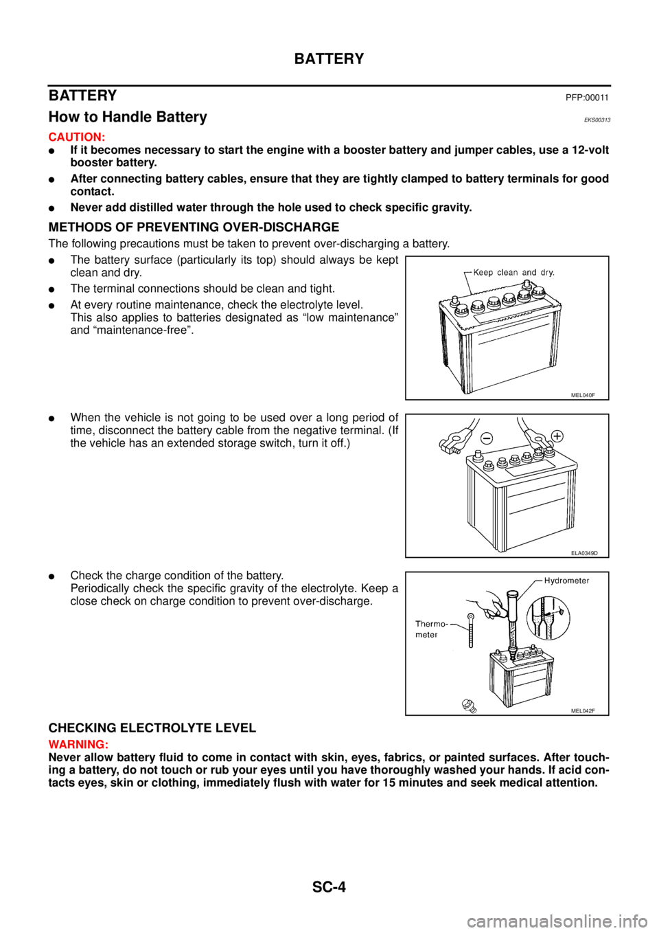
METHODS OF PREVENTING OVER-DISCHARGE
The following precautions must be taken to prevent over-discharging a battery.
�The battery surface (particularly its top) should always be kept
clean and dry.
�The terminal connections should be clean and tight.
�At every routine maintenance, check the electrolyte level.
This also applies to batteries designated as “low maintenance”
and “maintenance-free”.
�When the vehicle is not going to be used over a long period of
time, disconnect the battery cable from the negative terminal. (If
the vehicle has an extended storage switch, turn it off.)
�Check the charge condition of the battery.
Periodically check the specific gravity of the electrolyte. Keep a
close check on charge condition to prevent over-discharge.
CHECKING ELECTROLYTE LEVEL
WARNING:
Never allow battery fluid to come in contact with skin, eyes, fabrics, or painted surfaces. After touch-
ing a battery, do not touch or rub your eyes until you have thoroughly washed your hands. If acid con-
tacts eyes, skin or clothing, immediately flush with water for 15 minutes and seek medical attention.
MEL040F
ELA0349D
MEL042F
Page 3965 of 4555
BATTERY
SC-5
C
D
E
F
G
H
I
J
L
MA
B
SC
�Remove the cell plug using a suitable tool.
�Add distilled water up to the MAX level.
Sulphation
A battery will be completely discharged if it is left unattended
for a long time and the specific gravity will become less than
1.100. This may result in sulphation on the cell plates.
To determine if a battery has been “sulphated”, note its voltage
and current when charging it. As shown in the figure, less cur-
rent and higher voltage are observed in the initial stage of
charging sulphated batteries.
A sulphated battery may sometimes be brought back into ser-
vice by means of a long, slow charge, 12 hours or more, fol-
lowed by a battery capacity test.
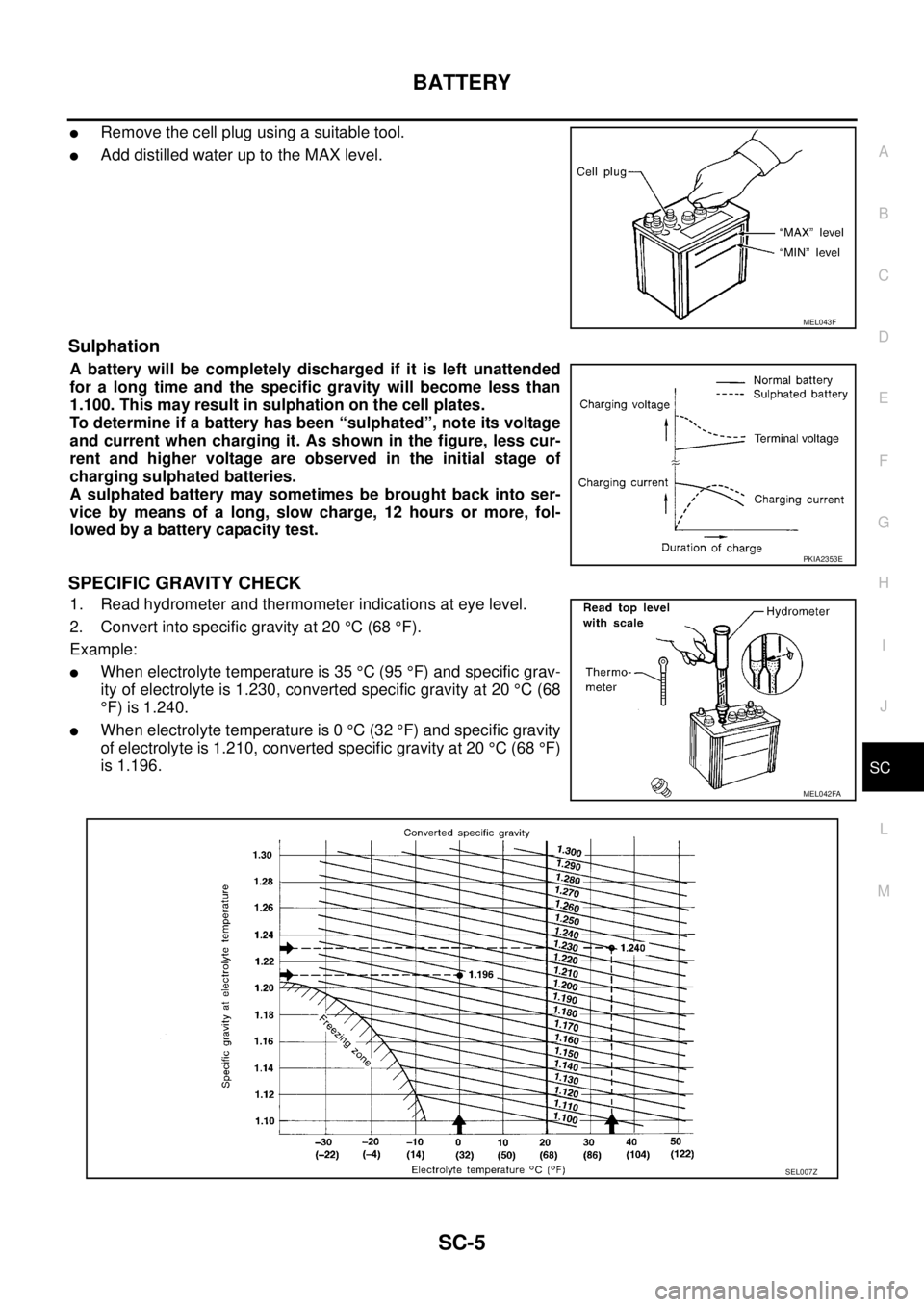
SPECIFIC GRAVITY CHECK
1. Read hydrometer and thermometer indications at eye level.
2. Convert into specific gravity at 20 °C (68 °F).
Example:
�When electrolyte temperature is 35 °C (95 °F) and specific grav-
ity of electrolyte is 1.230, converted specific gravity at 20 °C (68
°F) is 1.240.
�When electrolyte temperature is 0 °C (32 °F) and specific gravity
of electrolyte is 1.210, converted specific gravity at 20 °C (68 °F)
is 1.196.
MEL043F
PKIA2353E
MEL042FA
SEL007Z