Page 2951 of 4555

RAX-7
C
E
F
G
H
I
J
K
L
MA
B
RAX
INSTALLATION
�Install in the reverse order of removal. For tightening torque refer to RAX-6, \"COMPONENT\" .
�Perform final tightening of nuts and bolt")
WHEEL HUB (2WD)
RAX-7
C
E
F
G
H
I
J
K
L
MA
B
RAX
INSTALLATION
�Install in the reverse order of removal. For tightening torque refer to RAX-6, "COMPONENT" .
�Perform final tightening of nuts and bolts on each link mounting part (rubber bushing) under unladen con-
ditions with tires on level ground. Check wheel alignment. Refer to RSU-6, "
Wheel Alignment" .
�Check wheel sensor harness for proper connection. Refer to BRC-46, "WHEEL SENSORS" .
Disassembly and AssemblyEDS0034I
DISASSEMBLY
CAUTION:
Do not disassemble if wheel bearing has no trouble.
1. Remove caulked of lock nut, and then remove lock nut from axle housing.
2. Remove sensor rotor from axle housing.
3. Set axle housing on vise at point where strut is attached. Using
a sliding hammer [SST] and attachment [SST] to remove wheel
hub from axle housing.
CAUTION:
When placing on vise, be careful not to damage strut
mounting surface of axle housing. Use an aluminum plate
or suitable tool.
4. Using a drift [SST] and a puller (suitable tool), press wheel bear-
ing outer side inner race from wheel hub.
5. Using a flat-bladed screwdriver or similar tool to remove snap
ring from axle housing.
6. Using a drift [SST] and a press wheel bearing from axle housing.
FAC0104D
SDIA2440E
SDIA0155E
Page 2952 of 4555

INSPECTION AFTER DISASSEMBLY
Check for deformity, cracks and damage of each parts, replace if there are.
Wheel Hub
Check wheel hub for deformation, cracks, and other damage. If")
RAX-8
WHEEL HUB (2WD)
INSPECTION AFTER DISASSEMBLY
Check for deformity, cracks and damage of each parts, replace if there are.
Wheel Hub
Check wheel hub for deformation, cracks, and other damage. If any irregular conditions are found, replace if
there are.
Axle Housing
Inspect axle housing for deformation, cracks, and other damage. If any irregular conditions are found, replace
axle housing.
Snap Ring
Check snap ring for wear or other damage. If any irregular conditions are found, replace snap ring.
ASSEMBLY
1. Using a flat-bladed screwdriver or similar tool, install snap ring securely to the ditch of axle housing inner
side.
2. Using a drift [SST] to press wheel bearing securely from axle
housing inner side as far as it will go.
NOTE:
�Do not reuse wheel bearing.
�Final press load guideline 49,033 N (5,000 kg, 11,000 lb)
3. Using a drift [SST] to press wheel hub onto axle housing.
NOTE:
Final press load guideline 49,033 N (5,000 kg, 11,000 lb).
4. Set sensor rotor to axle housing.
NOTE:
Do not reuse sensor rotor.
5. Install lock nut to axle housing.
6. After installation of lock nut, be sure to perform caulking. Refer
to figure for caulking procedure.
INSPECTION AFTER ASSEMBLY
1. With wheel hub pressed into wheel bearing, apply 49,030 N (5,000 kg, 11,025 lb) to wheel hub and rotate
both clockwise and counterclockwise 10 times to minimize resistance.
2. At a rotating speed of 8 – 12 rpm, place a spring balance at the point where strut is joined (upper side
bolt hole). Measure rotating torque.
SDIA1349E
SDIA0157E
SDIA0964E
Page 2954 of 4555
RAX-10
WHEEL HUB (4WD)
WHEEL HUB (4WD)PFP:43202
On-Vehicle InspectionEDS00065
Inspect to check that there is no excessive play, cracking, wear, or other damage to rear axle.
�Turn rear wheels (left/right) and check the play.
REAR WHEEL BEARING
With vehicle raised, inspect the following.
�Move wheel hub in the axial direction by hand. Check that there is no looseness of rear wheel bearing.
�Rotate wheel hub and check that there is no unusual noise or other irregular condition. If there are any
irregular condition, replace wheel bearing.
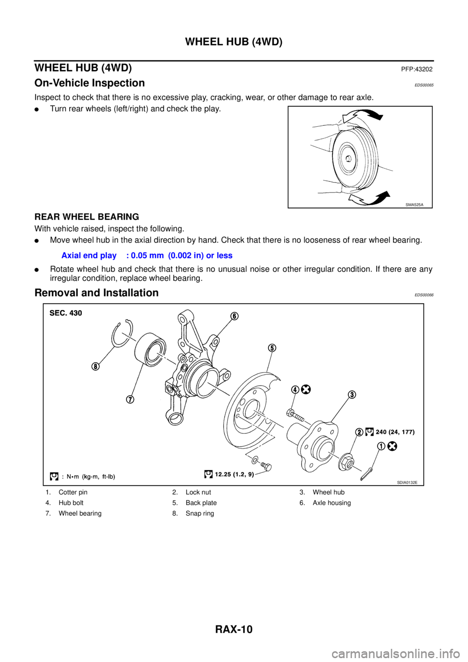
Removal and InstallationEDS00066
SMA525A
Axial end play : 0.05 mm (0.002 in) or less
1. Cotter pin 2. Lock nut 3. Wheel hub
4. Hub bolt 5. Back plate 6. Axle housing
7. Wheel bearing 8. Snap ring
SDIA0132E
Page 2956 of 4555

5. Use a drift (SST) to remove wheel bearing from axle housing.
INSPECTION AFTER DISASSEMBLY
Wheel Hub
�Inspect wheel hub for deformation, cracks, and other damage. If any irr")
RAX-12
WHEEL HUB (4WD)
5. Use a drift (SST) to remove wheel bearing from axle housing.
INSPECTION AFTER DISASSEMBLY
Wheel Hub
�Inspect wheel hub for deformation, cracks, and other damage. If any irregular conditions are found,
replace wheel hub.
Axle Housing
�Inspect axle housing for deformation, cracks, and other damage. If any irregular conditions are found,
replace axle housing.
Snap Ring
�Check snap ring for deformation, cracks, and other damage. If any irregular conditions are found, replace
snap ring.
ASSEMBLY
1. Use a drift (SST) to press fit wheel bearing into axle housing.
CAUTION:
Discard the old wheel bearing; replace with a new one.
2. Use a flat-bladed screwdriver or similar tool to install the snap
ring.
3. Install back plate and anchor block onto axle housing. Refer to
PB-4, "
Components" .
4. Use a drift (SST) to install wheel hub onto axle housing.
5. After completing step 4, apply an additional load of 49,030 N
(5,000 kg, 11,025 lb). Rotate axle housing in forward and
reverse directions 10 times each to ensure a good fit.
6. Place a spring balance at the point where the strut is joined (upper side bolt hole) and measure rotating
torque when spring is pulled at a speed of 8 -12 rpm. Refer to the RAX-19, "
Wheel Bearing" item.
NOTE:
If a load of 49,030 N (5,000 kg, 11,025 lb) cannot be applied:
�Install to drive shaft and tighten wheel hub lock nut to specified torque. Rotate in forward and reverse
direction 10 times each to ensure a good fit.
�At a rotating speed of 8 - 12 rpm, place a spring balance on hub bolt and measure rotating torque.
SDIA0155E
SDIA1349E
SDIA0157E
Rotating torque : 1.96 N·m (0.20 kg-m, 17 in-lb) or less
Spring balance reading : 12.8 N (1.30 kg, 2.87 lb) or less
Page 2958 of 4555

RAX-14
REAR DRIVE SHAFT
REAR DRIVE SHAFTPFP:39600
Removal and InstallationEDS000FL
REMOVAL
1. Remove axle housing. Refer to RAX-11, "REMOVAL" .
NOTE:
In order to remove the rear drive shaft assembly, the rear axle is removed. At this time it is recommended
that front and rear parallel links on axle side be loosened (not removed). This will facilitate wheel align-
ment inspection and adjustment which are carried out later.
2. As shown in the figure, use a wheel wrench or similar tool to
remove drive shaft from rear final drive.
INSPECTION AFTER REMOVAL
�Move the joint in the up/down, left/right, and axial directions. Check for any rough movement or significant
looseness.
�Check boot for cracks or other damage, and also for grease leakage.
INSTALLATION
1. In order to prevent damage to rear final drive side oil seal, first fit
a protector (SST) onto oil seal before inserting drive shaft. Slide
drive shaft into slide joint and tap with a hammer to install
securely.
CAUTION:
Be sure to check that circular clip is securely fastened.
2. Install rear axle. Refer to RAX-11, "
INSTALLATION" .
SDIA0604E
DSR0015D
DSR0010D
Page 2960 of 4555
 30 mm (1.18 in) or more
into threaded part of joint sub-assembly. Pull joint sub-assembly
out of shaft.
CAUTION:
If joint sub as")
RAX-16
REAR DRIVE SHAFT
4. Screw a drive shaft puller (suitable tool) 30 mm (1.18 in) or more
into threaded part of joint sub-assembly. Pull joint sub-assembly
out of shaft.
CAUTION:
If joint sub assembly cannot be removed after five or more
unsuccessful attempts, replace the entire drive shaft
assembly.
5. Remove boot from shaft.
6. Remove circular clip from shaft.
7. Remove old grease.
INSPECTION AFTER DISASSEMBLY
Shaft
�Replace shaft if there is any runout, cracking, or other damage.
Joint Sub-Assembly
�Check that there is no rough rotation or unusual axial looseness.
�Check that there is no foreign material inside joint.
CAUTION:
If there are any irregular conditions of joint assembly components, replace the entire joint assem-
bly.
Slide Joint Side
Housing and spider assembly
�If roller or roller surface of spider assembly has scratch or wear, replace housing and spider assembly.
NOTE:
Housing and spider assembly are components which are used as a set.
ASSEMBLY
Final Drive Side
1. Wind serrated part of drive shaft with tape. Install boot band and
boot to shaft. Be careful not to damage boot.
CAUTION:
Discard the old boot band and boot; replace with new ones.
2. Remove protective tape wound around serrated part of shaft.
3. Line up alignment marks which were made when spider assem-
bly was removed. Install spider assembly, with serration chamfer
facing drive shaft.
4. Secure spider assembly with snap ring.
CAUTION:
Discard the old snap ring; replace with a new one.
5. Apply grease (Nissan genuine grease or equivalent) to spider
assembly and sliding surface.
6. Install housing to spider assembly. Add remaining grease (Nis-
san genuine grease or equivalent) up to the amount listed
below.
SDIA0606E
SDIA0597E
Grease amount : 40 - 50 g (1.41 - 1.77 oz)
SDIA0598E
Page 2961 of 4555
 shown
in the figure.
CAUTION:
If there is grease on boot mounting surfaces (indicated")
REAR DRIVE SHAFT
RAX-17
C
E
F
G
H
I
J
K
L
MA
B
RAX
7. Install boot securely into grooves (indicated by * marks) shown
in the figure.
CAUTION:
If there is grease on boot mounting surfaces (indicated by *
marks) of joint, boot may come off. Remove all grease from
surfaces.
8. Check that boot installation length “L” is the length indicated
below. Insert a flat-bladed screwdriver or similar tool into smaller
side of boot. Remove air from boot to prevent boot deformation.
CAUTION:
�Boot may break if boot installation length is less than
standard value.
�Be careful that screwdriver tip does not contact inside
surface of boot.
9. Secure big and small ends of boot with new boot bands as
shown in figure.
CAUTION:
Rotate housing and check that boot installation position
does not change. If position changes, reinstall boot bands.
Wheel Side
1. Use a drift (SST) to press-fit sensor rotor into joint sub-assem-
bly.
CAUTION:
Discard the old sensor rotor; replace with a new one.
SDIA0599E
Boot installation length:
78.6 - 80.6 mm (3.094 - 3.173 in)
SDIA0600E
SFA395
SDIA0602E
Page 2962 of 4555

RAX-18
REAR DRIVE SHAFT
2. Wind serrated part of drive shaft with tape. Install boot band and
boot to shaft. Be careful not to damage boot.
CAUTION:
Discard the old boot band and boot; replace with new ones.
3. Remove protective tape wound around serrated part of shaft.
4. Attach circular clip to shaft. At this time, circular clip must fit
securely into the shaft groove. Attach nut to joint sub-assembly.
Use a wooden hammer to press-fit.
CAUTION:
Discard the old circular clip; replace with a new one.
5. Insert the amount of grease (Nissan genuine grease or equiva-
lent) listed below into housing from large end of boot.
6. Install boot securely into grooves (indicated by * marks) shown
in the figure.
CAUTION:
If there is grease on boot mounting surfaces (indicated by *
marks) of joint sub-assembly, boot may come off. Remove
all grease from surfaces.
7. Check that boot installation length “L” is the length indicated
below. Insert a flat-bladed screwdriver or similar tool into smaller
side of boot. Remove air from boot to prevent boot deformation.
CAUTION:
�Boot may break if boot installation length is less than standard value.
�Be careful that screwdriver tip does not contact inside surface of boot.
8. Secure big and small ends of boot with new boot bands as
shown in the figure.
CAUTION:
Rotate housing and check that boot installation position
does not change. If position changes, reinstall boot bands.
SDIA0597E
Grease amount : 35 - 45 g (1.23 - 1.59 oz)
RAC0049D
Boot installation length:
66.7 - 68.7 mm (2.626 - 2.705 in)SDIA0607E
SFA395