Page 2920 of 4555
RFD-30
REAR FINAL DRIVE ASSEMBLY
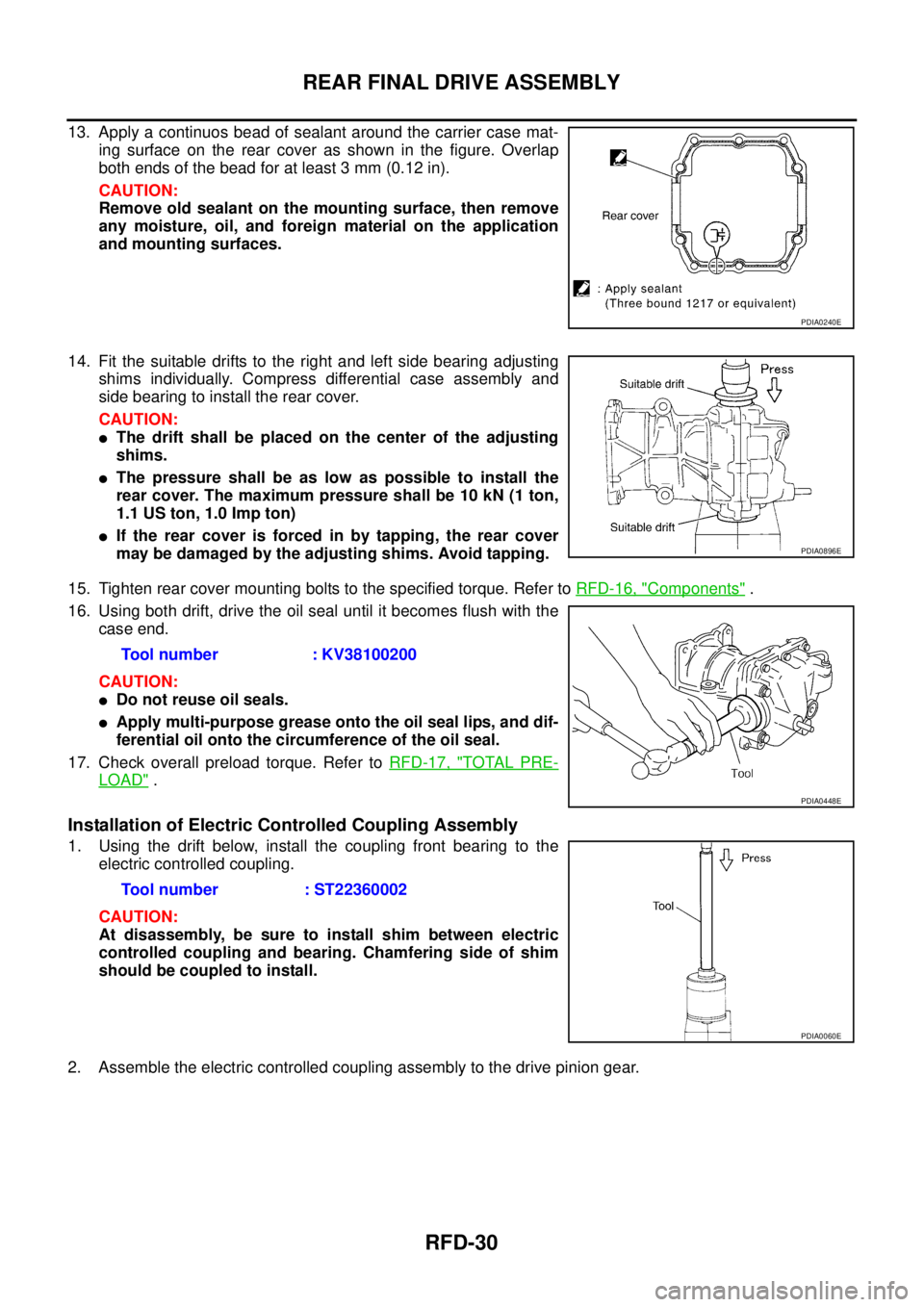
13. Apply a continuos bead of sealant around the carrier case mat-
ing surface on the rear cover as shown in the figure. Overlap
both ends of the bead for at least 3 mm (0.12 in).
CAUTION:
Remove old sealant on the mounting surface, then remove
any moisture, oil, and foreign material on the application
and mounting surfaces.
14. Fit the suitable drifts to the right and left side bearing adjusting
shims individually. Compress differential case assembly and
side bearing to install the rear cover.
CAUTION:
�The drift shall be placed on the center of the adjusting
shims.
�The pressure shall be as low as possible to install the
rear cover. The maximum pressure shall be 10 kN (1 ton,
1.1 US ton, 1.0 Imp ton)
�If the rear cover is forced in by tapping, the rear cover
may be damaged by the adjusting shims. Avoid tapping.
15. Tighten rear cover mounting bolts to the specified torque. Refer to RFD-16, "
Components" .
16. Using both drift, drive the oil seal until it becomes flush with the
case end.
CAUTION:
�Do not reuse oil seals.
�Apply multi-purpose grease onto the oil seal lips, and dif-
ferential oil onto the circumference of the oil seal.
17. Check overall preload torque. Refer to RFD-17, "
TOTAL PRE-
LOAD" .
Installation of Electric Controlled Coupling Assembly
1. Using the drift below, install the coupling front bearing to the
electric controlled coupling.
CAUTION:
At disassembly, be sure to install shim between electric
controlled coupling and bearing. Chamfering side of shim
should be coupled to install.
2. Assemble the electric controlled coupling assembly to the drive pinion gear.
PDIA0240E
PDIA0896E
Tool number : KV38100200
PDIA0448E
Tool number : ST22360002
PDIA0060E
Page 2921 of 4555
REAR FINAL DRIVE ASSEMBLY
RFD-31
C
E
F
G
H
I
J
K
L
MA
B
RFD
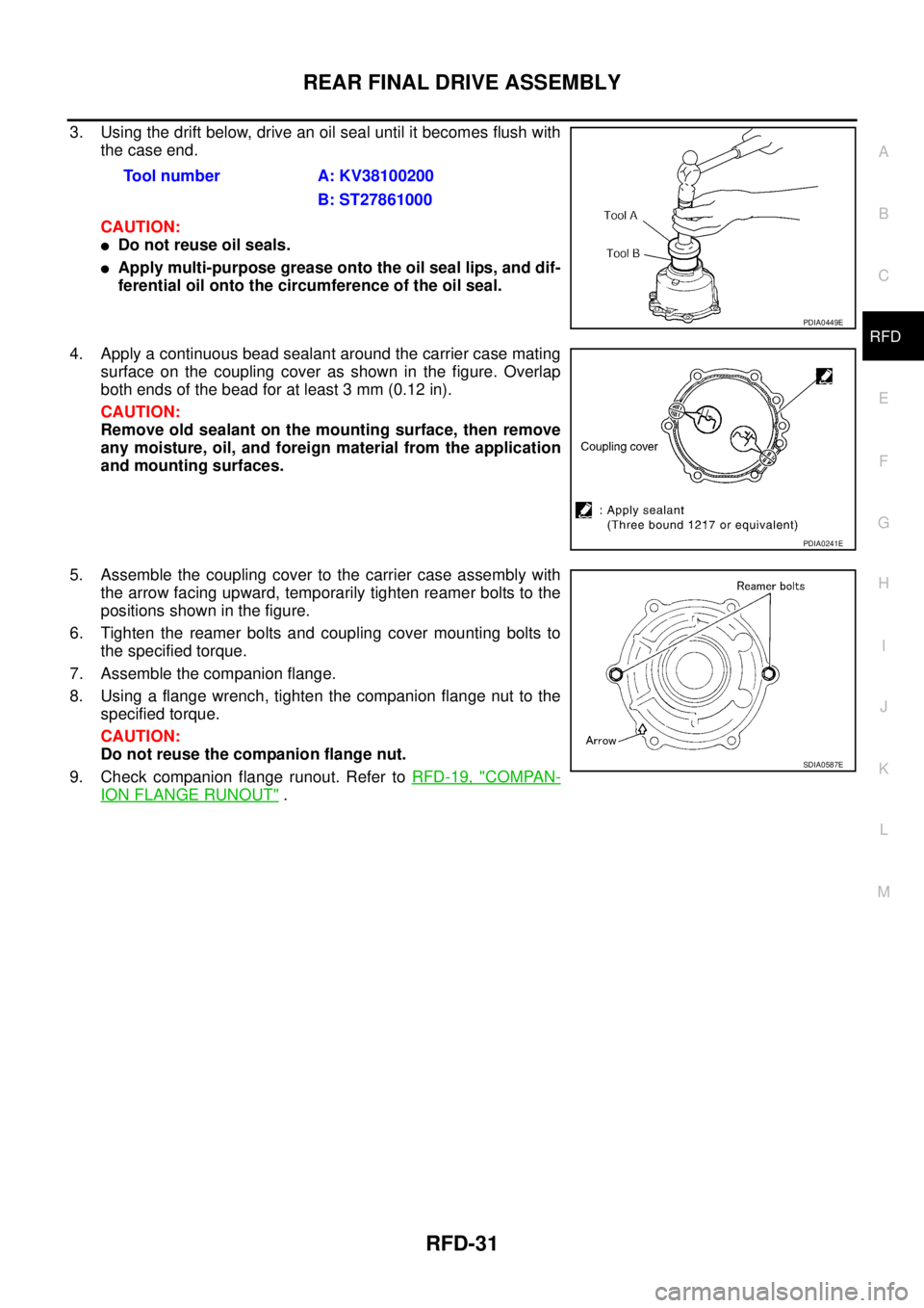
3. Using the drift below, drive an oil seal until it becomes flush with
the case end.
CAUTION:
�Do not reuse oil seals.
�Apply multi-purpose grease onto the oil seal lips, and dif-
ferential oil onto the circumference of the oil seal.
4. Apply a continuous bead sealant around the carrier case mating
surface on the coupling cover as shown in the figure. Overlap
both ends of the bead for at least 3 mm (0.12 in).
CAUTION:
Remove old sealant on the mounting surface, then remove
any moisture, oil, and foreign material from the application
and mounting surfaces.
5. Assemble the coupling cover to the carrier case assembly with
the arrow facing upward, temporarily tighten reamer bolts to the
positions shown in the figure.
6. Tighten the reamer bolts and coupling cover mounting bolts to
the specified torque.
7. Assemble the companion flange.
8. Using a flange wrench, tighten the companion flange nut to the
specified torque.
CAUTION:
Do not reuse the companion flange nut.
9. Check companion flange runout. Refer to RFD-19, "
COMPAN-
ION FLANGE RUNOUT" . Tool number A: KV38100200
B: ST27861000
PDIA0449E
PDIA0241E
SDIA0587E
Page 2922 of 4555
RFD-32
SERVICE DATA AND SPECIFICATIONS (SDS)
SERVICE DATA AND SPECIFICATIONS (SDS)PFP:00030
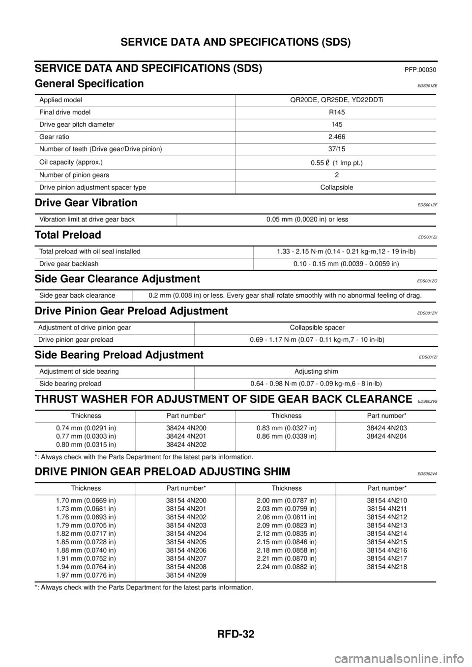
General SpecificationEDS001ZE
Drive Gear VibrationEDS001ZF
To ta l P r e l o a dEDS001ZJ
Side Gear Clearance AdjustmentEDS001ZG
Drive Pinion Gear Preload AdjustmentEDS001ZH
Side Bearing Preload AdjustmentEDS001ZI
THRUST WASHER FOR ADJUSTMENT OF SIDE GEAR BACK CLEARANCEEDS002V9
*: Always check with the Parts Department for the latest parts information.
DRIVE PINION GEAR PRELOAD ADJUSTING SHIMEDS002VA
*: Always check with the Parts Department for the latest parts information.Applied model QR20DE, QR25DE, YD22DDTi
Final drive modelR145
Drive gear pitch diameter 145
Gear ratio2.466
Number of teeth (Drive gear/Drive pinion) 37/15
Oil capacity (approx.)
0.55 (1 lmp pt.)
Number of pinion gears2
Drive pinion adjustment spacer type Collapsible
Vibration limit at drive gear back 0.05 mm (0.0020 in) or less
Total preload with oil seal installed 1.33 - 2.15 N·m (0.14 - 0.21 kg-m,12 - 19 in-lb)
Drive gear backlash 0.10 - 0.15 mm (0.0039 - 0.0059 in)
Side gear back clearance 0.2 mm (0.008 in) or less. Every gear shall rotate smoothly with no abnormal feeling of drag.
Adjustment of drive pinion gear Collapsible spacer
Drive pinion gear preload 0.69 - 1.17 N·m (0.07 - 0.11 kg-m,7 - 10 in-lb)
Adjustment of side bearing Adjusting shim
Side bearing preload 0.64 - 0.98 N·m (0.07 - 0.09 kg-m,6 - 8 in-lb)
Thickness Part number* Thickness Part number*
0.74 mm (0.0291 in)
0.77 mm (0.0303 in)
0.80 mm (0.0315 in)38424 4N200
38424 4N201
38424 4N2020.83 mm (0.0327 in)
0.86 mm (0.0339 in)38424 4N203
38424 4N204
Thickness Part number* Thickness Part number*
1.70 mm (0.0669 in)
1.73 mm (0.0681 in)
1.76 mm (0.0693 in)
1.79 mm (0.0705 in)
1.82 mm (0.0717 in)
1.85 mm (0.0728 in)
1.88 mm (0.0740 in)
1.91 mm (0.0752 in)
1.94 mm (0.0764 in)
1.97 mm (0.0776 in)38154 4N200
38154 4N201
38154 4N202
38154 4N203
38154 4N204
38154 4N205
38154 4N206
38154 4N207
38154 4N208
38154 4N2092.00 mm (0.0787 in)
2.03 mm (0.0799 in)
2.06 mm (0.0811 in)
2.09 mm (0.0823 in)
2.12 mm (0.0835 in)
2.15 mm (0.0846 in)
2.18 mm (0.0858 in)
2.21 mm (0.0870 in)
2.24 mm (0.0882 in)38154 4N210
38154 4N211
38154 4N212
38154 4N213
38154 4N214
38154 4N215
38154 4N216
38154 4N217
38154 4N218
Page 2923 of 4555
SERVICE DATA AND SPECIFICATIONS (SDS)
RFD-33
C
E
F
G
H
I
J
K
L
MA
B
RFD
ADJUSTING SHIM FOR SIDE BEARING PRELOADEDS002VB
*: Always check with the Parts Department for the latest parts information.Thickness Part number* Thickness Part number*
1.85 mm (0.0728 in)
1.90 mm (0.0748 in)
1.95 mm (0.0768 in)
2.00 mm (0.0787 in)38453 4N200
38453 4N201
38453 4N202
38453 4N2032.05 mm (0.0807 in)
2.10 mm (0.0827 in)
2.15 mm (0.0854 in)
2.20 mm (0.0866 in)38453 4N204
38453 4N205
38453 4N206
38453 4N207
Page 2926 of 4555
FAX-2
PRECAUTIONS
PRECAUTIONSPFP:00001
CautionEDS0005P
�When installing rubber parts, final tightening must be carried out under unladen condition* with tires on
ground.
�Oil will shorten the life of rubber bushes. Be sure to wipe off any spilled oil.
*: Fuel, radiator coolant and engine oil full. Spare tire, jack, hand tools and mats in designated positions.
�After installing removed suspension parts, check wheel alignment and adjust if necessary.
Observe the following precautions when disassembling and servicing drive shaft.
�Perform work in a location which is as dust-free as possible.
�Before disassembling and servicing, clean the outside of parts.
�Prevention of the entry of foreign objects must be taken into account during disassembly of the service
location.
�Disassembled parts must be carefully reassembled in the correct order. If work is interrupted, a clean
cover must be placed over parts.
�Paper shop cloths must be used. Fabric shop cloths must not be used because of the danger of lint adher-
ing to parts.
�Disassembled parts (except for rubber parts) should be cleaned with kerosene which shall be removed by
blowing with air or wiping with paper shop cloths.
Page 2931 of 4555
FRONT WHEEL HUB AND KNUCKLE
FAX-7
C
E
F
G
H
I
J
K
L
MA
B
FA X
FRONT WHEEL HUB AND KNUCKLEPFP:40202
On-Vehicle InspectionEDS0005R
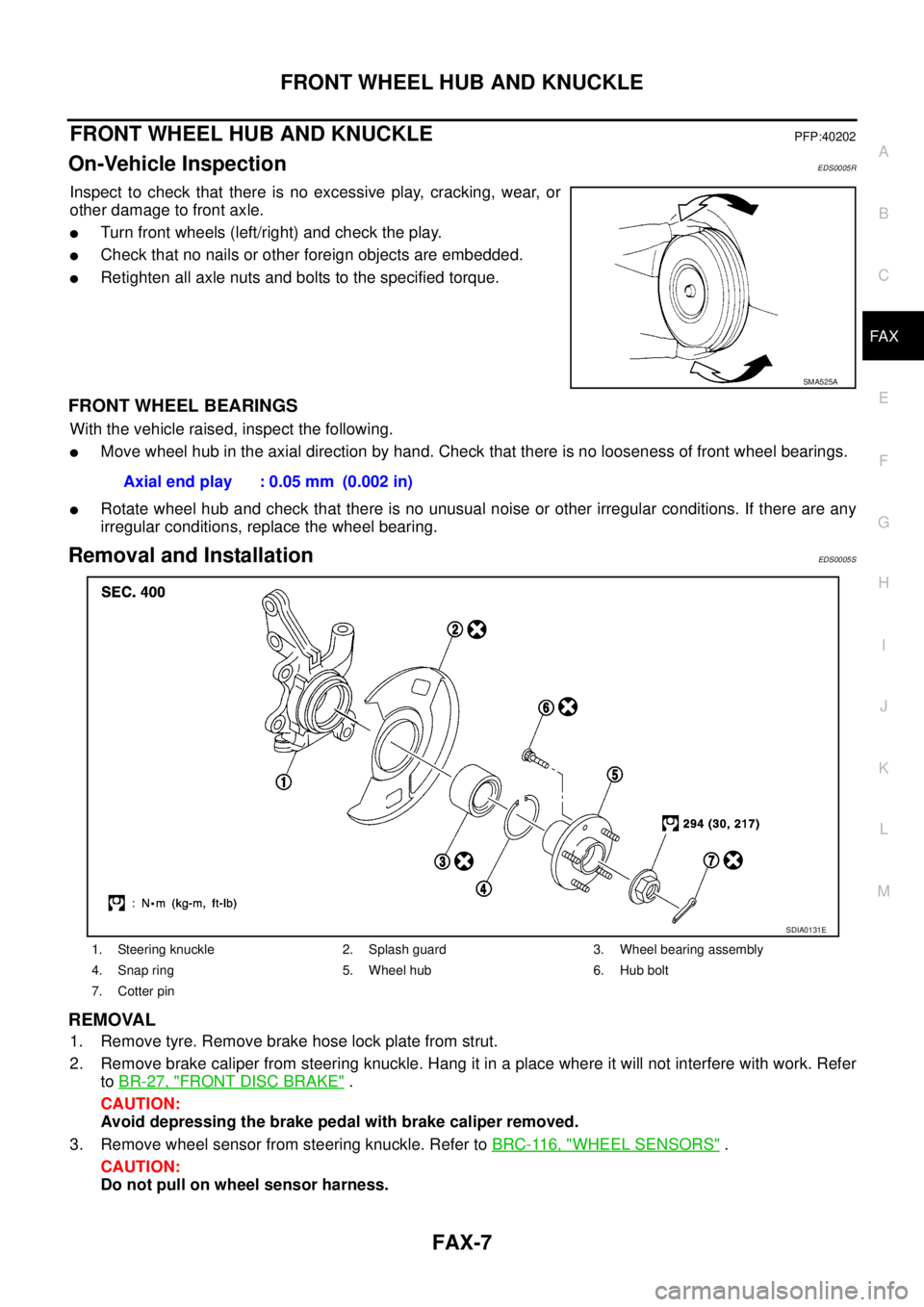
Inspect to check that there is no excessive play, cracking, wear, or
other damage to front axle.
�Turn front wheels (left/right) and check the play.
�Check that no nails or other foreign objects are embedded.
�Retighten all axle nuts and bolts to the specified torque.
FRONT WHEEL BEARINGS
With the vehicle raised, inspect the following.
�Move wheel hub in the axial direction by hand. Check that there is no looseness of front wheel bearings.
�Rotate wheel hub and check that there is no unusual noise or other irregular conditions. If there are any
irregular conditions, replace the wheel bearing.
Removal and InstallationEDS0005S
REMOVAL
1. Remove tyre. Remove brake hose lock plate from strut.
2. Remove brake caliper from steering knuckle. Hang it in a place where it will not interfere with work. Refer
to BR-27, "
FRONT DISC BRAKE" .
CAUTION:
Avoid depressing the brake pedal with brake caliper removed.
3. Remove wheel sensor from steering knuckle. Refer to BRC-116, "
WHEEL SENSORS" .
CAUTION:
Do not pull on wheel sensor harness.
SMA525A
Axial end play : 0.05 mm (0.002 in)
1. Steering knuckle 2. Splash guard 3. Wheel bearing assembly
4. Snap ring 5. Wheel hub 6. Hub bolt
7. Cotter pin
SDIA0131E
Page 2932 of 4555
FAX-8
FRONT WHEEL HUB AND KNUCKLE
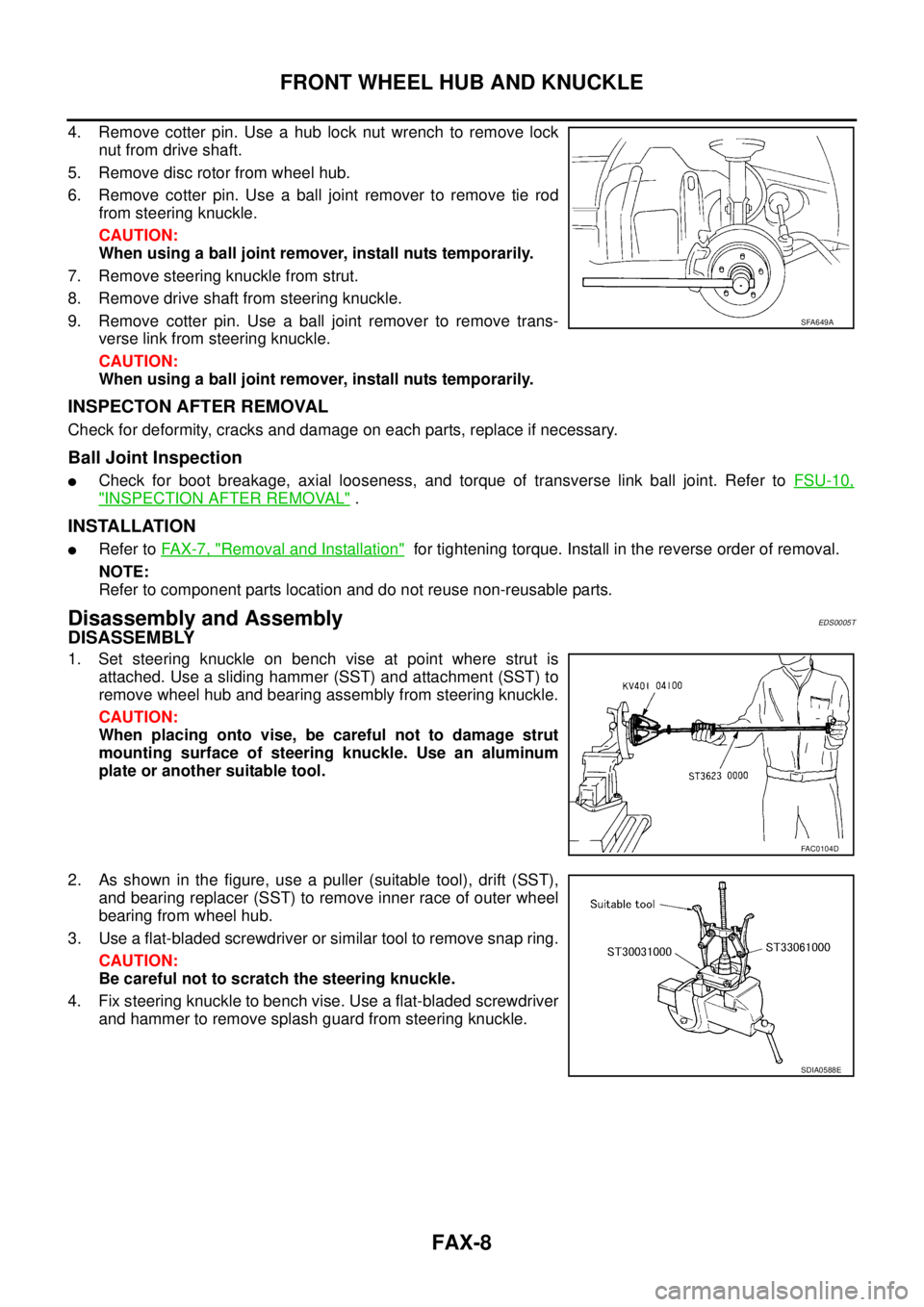
4. Remove cotter pin. Use a hub lock nut wrench to remove lock
nut from drive shaft.
5. Remove disc rotor from wheel hub.
6. Remove cotter pin. Use a ball joint remover to remove tie rod
from steering knuckle.
CAUTION:
When using a ball joint remover, install nuts temporarily.
7. Remove steering knuckle from strut.
8. Remove drive shaft from steering knuckle.
9. Remove cotter pin. Use a ball joint remover to remove trans-
verse link from steering knuckle.
CAUTION:
When using a ball joint remover, install nuts temporarily.
INSPECTON AFTER REMOVAL
Check for deformity, cracks and damage on each parts, replace if necessary.
Ball Joint Inspection
�Check for boot breakage, axial looseness, and torque of transverse link ball joint. Refer to FSU-10,
"INSPECTION AFTER REMOVAL" .
INSTALLATION
�Refer to FAX-7, "Removal and Installation" for tightening torque. Install in the reverse order of removal.
NOTE:
Refer to component parts location and do not reuse non-reusable parts.
Disassembly and AssemblyEDS0005T
DISASSEMBLY
1. Set steering knuckle on bench vise at point where strut is
attached. Use a sliding hammer (SST) and attachment (SST) to
remove wheel hub and bearing assembly from steering knuckle.
CAUTION:
When placing onto vise, be careful not to damage strut
mounting surface of steering knuckle. Use an aluminum
plate or another suitable tool.
2. As shown in the figure, use a puller (suitable tool), drift (SST),
and bearing replacer (SST) to remove inner race of outer wheel
bearing from wheel hub.
3. Use a flat-bladed screwdriver or similar tool to remove snap ring.
CAUTION:
Be careful not to scratch the steering knuckle.
4. Fix steering knuckle to bench vise. Use a flat-bladed screwdriver
and hammer to remove splash guard from steering knuckle.
SFA649A
FAC0104D
SDIA0588E
Page 2933 of 4555
FRONT WHEEL HUB AND KNUCKLE
FAX-9
C
E
F
G
H
I
J
K
L
MA
B
FA X
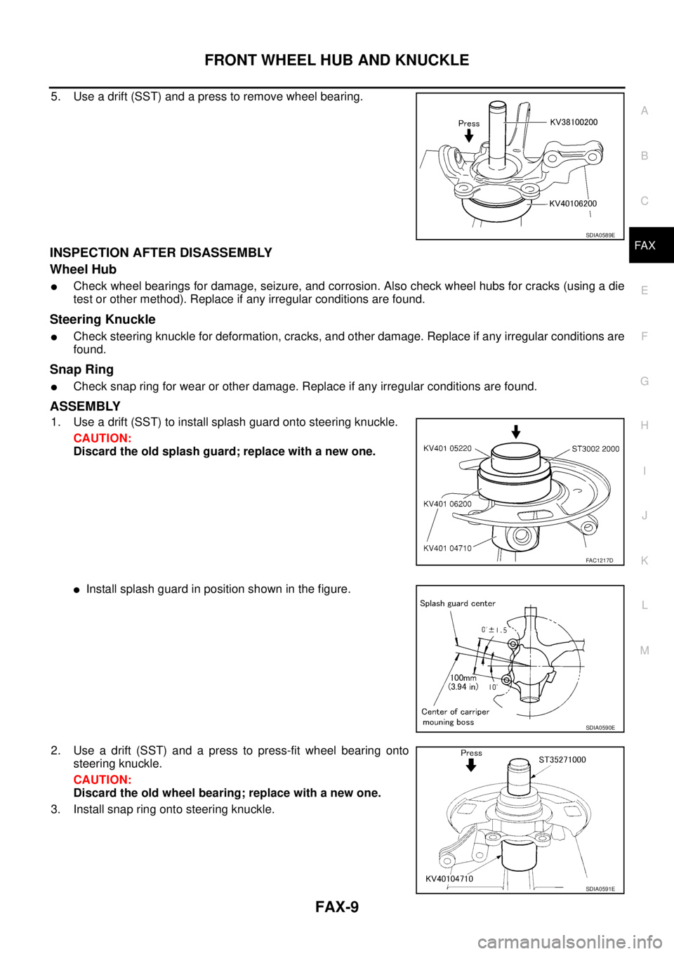
5. Use a drift (SST) and a press to remove wheel bearing.
INSPECTION AFTER DISASSEMBLY
Wheel Hub
�Check wheel bearings for damage, seizure, and corrosion. Also check wheel hubs for cracks (using a die
test or other method). Replace if any irregular conditions are found.
Steering Knuckle
�Check steering knuckle for deformation, cracks, and other damage. Replace if any irregular conditions are
found.
Snap Ring
�Check snap ring for wear or other damage. Replace if any irregular conditions are found.
ASSEMBLY
1. Use a drift (SST) to install splash guard onto steering knuckle.
CAUTION:
Discard the old splash guard; replace with a new one.
�Install splash guard in position shown in the figure.
2. Use a drift (SST) and a press to press-fit wheel bearing onto
steering knuckle.
CAUTION:
Discard the old wheel bearing; replace with a new one.
3. Install snap ring onto steering knuckle.
SDIA0589E
FAC1217D
SDIA0590E
SDIA0591E