Page 3004 of 4555
BR-6
BRAKE PEDAL
BRAKE PEDALPFP:46501
On-Vehicle Inspection and AdjustmentEFS000C1
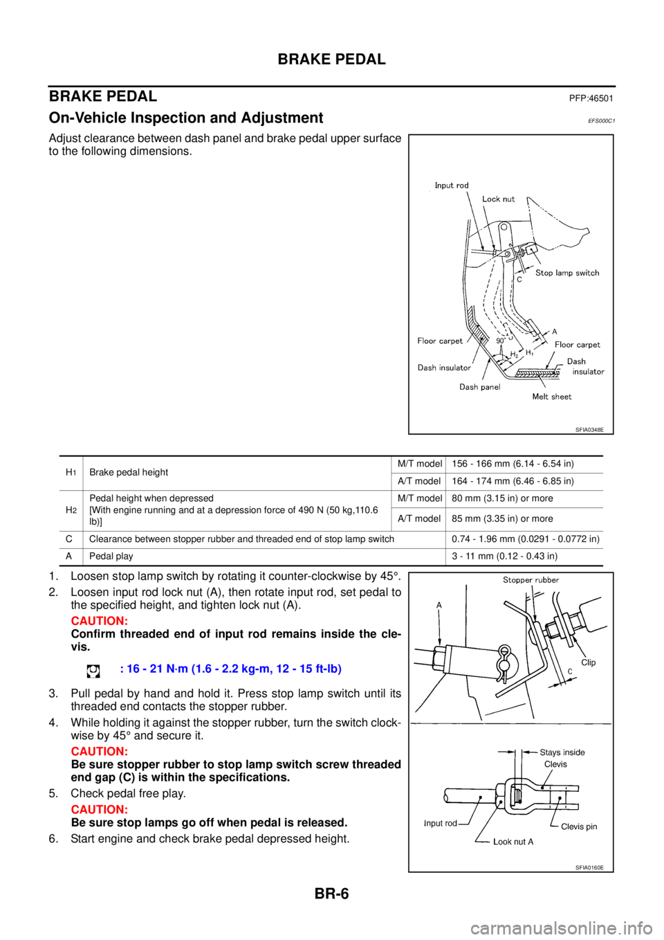
Adjust clearance between dash panel and brake pedal upper surface
to the following dimensions.
1. Loosen stop lamp switch by rotating it counter-clockwise by 45°.
2. Loosen input rod lock nut (A), then rotate input rod, set pedal to
the specified height, and tighten lock nut (A).
CAUTION:
Confirm threaded end of input rod remains inside the cle-
vis.
3. Pull pedal by hand and hold it. Press stop lamp switch until its
threaded end contacts the stopper rubber.
4. While holding it against the stopper rubber, turn the switch clock-
wise by 45° and secure it.
CAUTION:
Be sure stopper rubber to stop lamp switch screw threaded
end gap (C) is within the specifications.
5. Check pedal free play.
CAUTION:
Be sure stop lamps go off when pedal is released.
6. Start engine and check brake pedal depressed height.
SFIA0348E
H1Brake pedal heightM/T model 156 - 166 mm (6.14 - 6.54 in)
A/T model 164 - 174 mm (6.46 - 6.85 in)
H
2
Pedal height when depressed
[With engine running and at a depression force of 490 N (50 kg,110.6
lb)]M/T model 80 mm (3.15 in) or more
A/T model 85 mm (3.35 in) or more
C Clearance between stopper rubber and threaded end of stop lamp switch 0.74 - 1.96 mm (0.0291 - 0.0772 in)
A Pedal play3 - 11 mm (0.12 - 0.43 in)
: 16 - 21 N·m (1.6 - 2.2 kg-m, 12 - 15 ft-lb)
SFIA0160E
Page 3005 of 4555
BRAKE PEDAL
BR-7
C
D
E
G
H
I
J
K
L
MA
B
BR
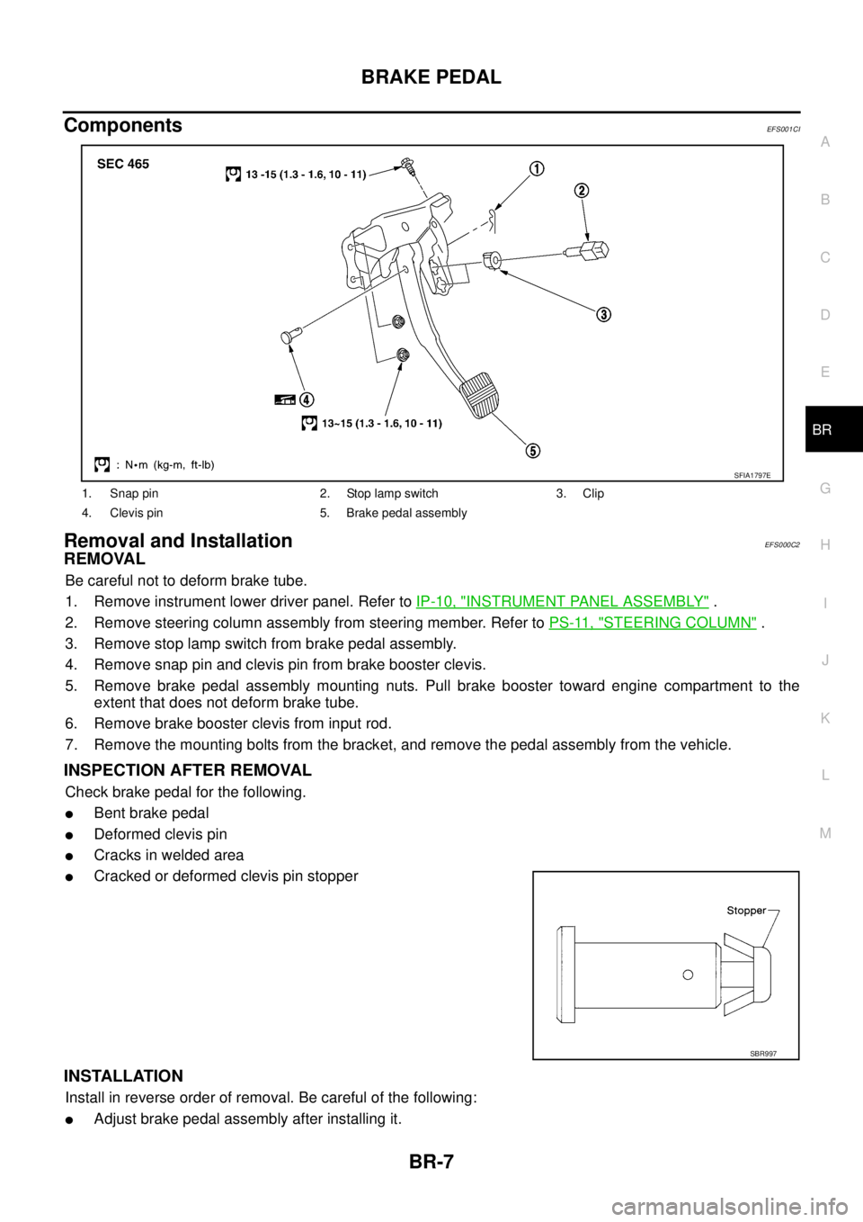
ComponentsEFS001CI
Removal and InstallationEFS000C2
REMOVAL
Be careful not to deform brake tube.
1. Remove instrument lower driver panel. Refer to IP-10, "
INSTRUMENT PANEL ASSEMBLY" .
2. Remove steering column assembly from steering member. Refer to PS-11, "
STEERING COLUMN" .
3. Remove stop lamp switch from brake pedal assembly.
4. Remove snap pin and clevis pin from brake booster clevis.
5. Remove brake pedal assembly mounting nuts. Pull brake booster toward engine compartment to the
extent that does not deform brake tube.
6. Remove brake booster clevis from input rod.
7. Remove the mounting bolts from the bracket, and remove the pedal assembly from the vehicle.
INSPECTION AFTER REMOVAL
Check brake pedal for the following.
�Bent brake pedal
�Deformed clevis pin
�Cracks in welded area
�Cracked or deformed clevis pin stopper
INSTALLATION
Install in reverse order of removal. Be careful of the following:
�Adjust brake pedal assembly after installing it.
1. Snap pin 2. Stop lamp switch 3. Clip
4. Clevis pin 5. Brake pedal assembly
SFIA1797E
SBR997
Page 3006 of 4555
BR-8
BRAKE FLUID
BRAKE FLUIDPFP:KN100
Checking Brake Fluid Level EFS000C5
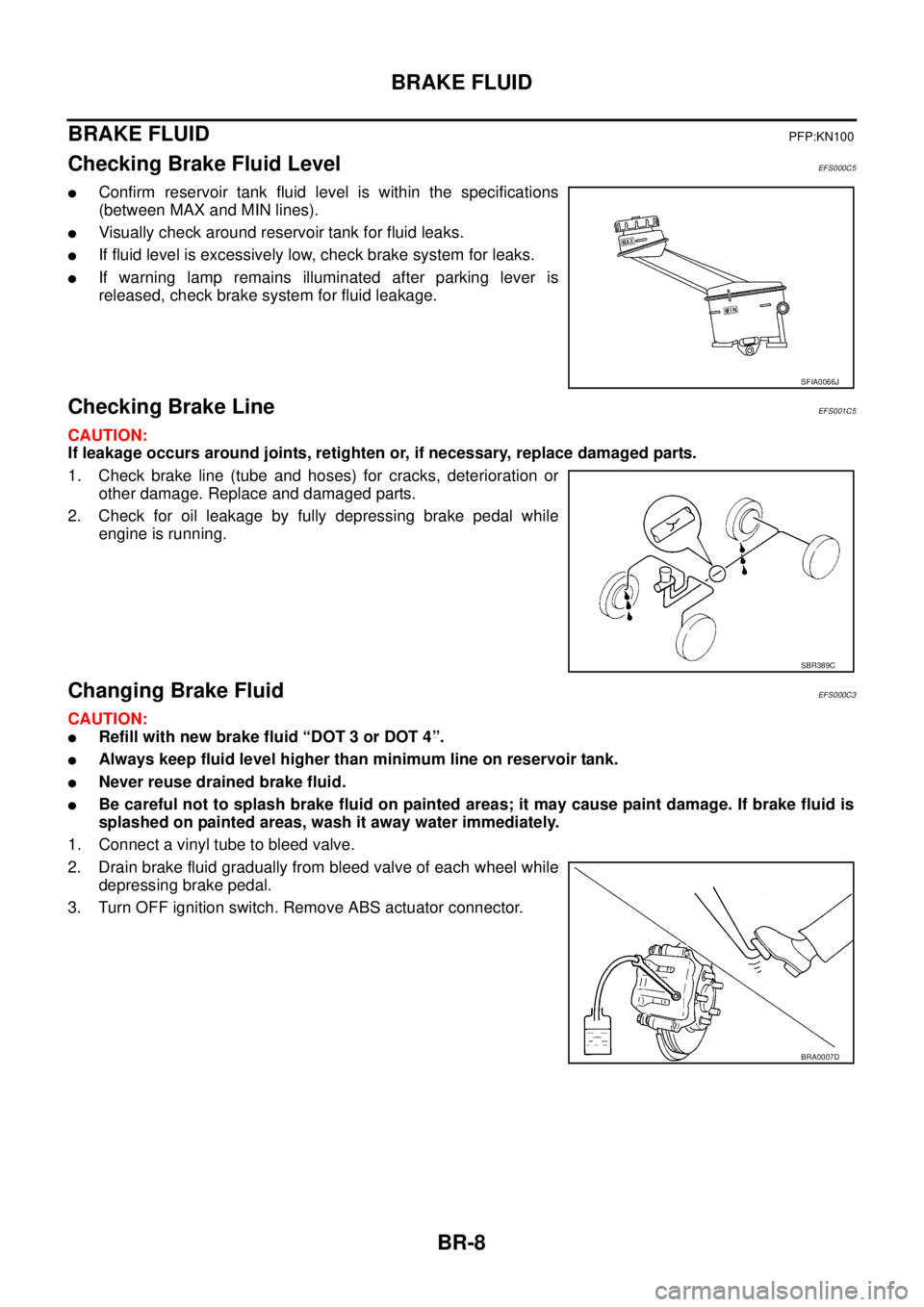
�Confirm reservoir tank fluid level is within the specifications
(between MAX and MIN lines).
�Visually check around reservoir tank for fluid leaks.
�If fluid level is excessively low, check brake system for leaks.
�If warning lamp remains illuminated after parking lever is
released, check brake system for fluid leakage.
Checking Brake LineEFS001C5
CAUTION:
If leakage occurs around joints, retighten or, if necessary, replace damaged parts.
1. Check brake line (tube and hoses) for cracks, deterioration or
other damage. Replace and damaged parts.
2. Check for oil leakage by fully depressing brake pedal while
engine is running.
Changing Brake FluidEFS000C3
CAUTION:
�Refill with new brake fluid “DOT 3 or DOT 4”.
�Always keep fluid level higher than minimum line on reservoir tank.
�Never reuse drained brake fluid.
�Be careful not to splash brake fluid on painted areas; it may cause paint damage. If brake fluid is
splashed on painted areas, wash it away water immediately.
1. Connect a vinyl tube to bleed valve.
2. Drain brake fluid gradually from bleed valve of each wheel while
depressing brake pedal.
3. Turn OFF ignition switch. Remove ABS actuator connector.
SFIA0066J
SBR389C
BRA0007D
Page 3011 of 4555
BRAKE PIPING AND HOSE
BR-13
C
D
E
G
H
I
J
K
L
MA
B
BR
3. Tighten flare nut by using a flare nut wrench with the specified
torque.
4. Refill brake fluid until new brake fluid comes out of each bleed
valve.
5. Afterwards, bleed air.
InspectionEFS000C9
CAUTION:
If any leaks on joints, retighten it. Replace any damaged parts.
1. Check hose, tube, and joints for fluid leaks, damage, twist, deformation, contact with other parts, and
loose connections.
2. Run engine. Depress brake pedal and hold it for approximately 5 seconds while checking each part for
leaks.: 15 - 17 N·m (1.5 - 1.8 kg-m, 11 - 13 ft-lb)
SBR820BA
Page 3013 of 4555
BRAKE MASTER CYLINDER
BR-15
C
D
E
G
H
I
J
K
L
MA
B
BR
5. Refill with new brake fluid and bleed air from the brake piping.
Disassembly and AssemblyEFS001CH
MODELS WITHOUT ESP (PISTON STOPPER APPLIED.)
Disassembly
CAUTION:
Remove master cylinder reservoir tank only when necessary.
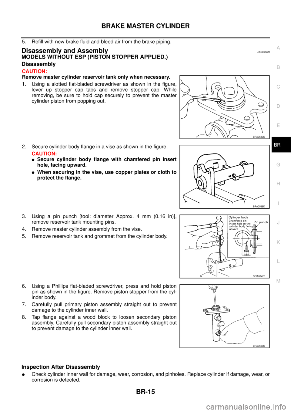
1. Using a slotted flat-bladed screwdriver as shown in the figure,
lever up stopper cap tabs and remove stopper cap. While
removing, be sure to hold cap securely to prevent the master
cylinder piston from popping out.
2. Secure cylinder body flange in a vise as shown in the figure.
CAUTION:
�Secure cylinder body flange with chamfered pin insert
hole, facing upward.
�When securing in the vise, use copper plates or cloth to
protect the flange.
3. Using a pin punch [tool: diameter Approx. 4 mm (0.16 in)],
remove reservoir tank mounting pins.
4. Remove master cylinder assembly from the vise.
5. Remove reservoir tank and grommet from the cylinder body.
6. Using a Phillips flat-bladed screwdriver, press and hold piston
pin as shown in the figure. Remove piston stopper from the cyl-
inder body.
7. Carefully pull primary piston assembly straight out to prevent
damage to the cylinder inner wall.
8. Tap flange against a wood block to loosen secondary piston
assembly. Carefully pull secondary piston assembly straight out
to prevent damage to the cylinder inner wall.
Inspection After Disassembly
�Check cylinder inner wall for damage, wear, corrosion, and pinholes. Replace cylinder if damage, wear, or
corrosion is detected.
BRA0533D
BRA0588D
SFIA0342E
BRA0590D
Page 3014 of 4555
BR-16
BRAKE MASTER CYLINDER
Assembly
CAUTION:
�Never use mineral oils such as kerosene or gasoline during the cleaning and assembly processes.
�Be sure there is no foreign material on the cylinder inner wall, piston, and cup seal. Be careful not
to damage parts with a service tool during assembly.
�Do not drop the parts. Do not use any dropped parts.
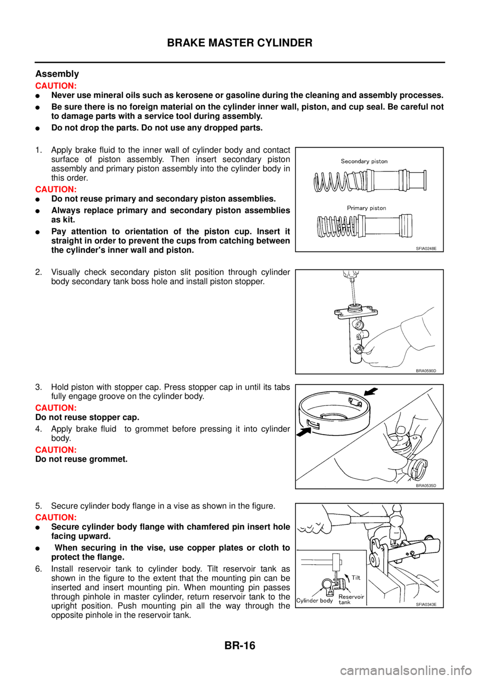
1. Apply brake fluid to the inner wall of cylinder body and contact
surface of piston assembly. Then insert secondary piston
assembly and primary piston assembly into the cylinder body in
this order.
CAUTION:
�Do not reuse primary and secondary piston assemblies.
�Always replace primary and secondary piston assemblies
as kit.
�Pay attention to orientation of the piston cup. Insert it
straight in order to prevent the cups from catching between
the cylinder's inner wall and piston.
2. Visually check secondary piston slit position through cylinder
body secondary tank boss hole and install piston stopper.
3. Hold piston with stopper cap. Press stopper cap in until its tabs
fully engage groove on the cylinder body.
CAUTION:
Do not reuse stopper cap.
4. Apply brake fluid to grommet before pressing it into cylinder
body.
CAUTION:
Do not reuse grommet.
5. Secure cylinder body flange in a vise as shown in the figure.
CAUTION:
�Secure cylinder body flange with chamfered pin insert hole
facing upward.
� When securing in the vise, use copper plates or cloth to
protect the flange.
6. Install reservoir tank to cylinder body. Tilt reservoir tank as
shown in the figure to the extent that the mounting pin can be
inserted and insert mounting pin. When mounting pin passes
through pinhole in master cylinder, return reservoir tank to the
upright position. Push mounting pin all the way through the
opposite pinhole in the reservoir tank.
SFIA0248E
BRA0590D
BRA0535D
SFIA0343E
Page 3015 of 4555
BRAKE MASTER CYLINDER
BR-17
C
D
E
G
H
I
J
K
L
MA
B
BR
CAUTION:
�Do not reuse reservoir tank mounting pin.
�Do not reuse reservoir tank.
�Be sure to insert pin from the chamfered pinhole on the cylinder body.
MODELS WITHOUT ESP (PISTON STOPPER NOT APPLIED.)
CAUTION:
Remove reservoir tank only when absolutely necessary.
Disassembly (Piston Assembly)
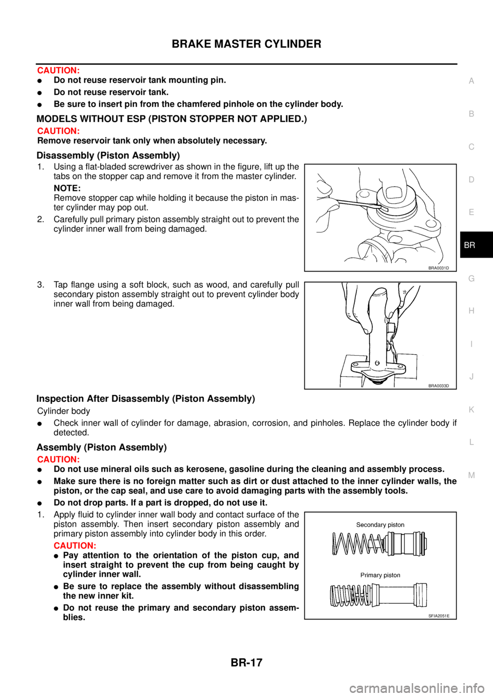
1. Using a flat-bladed screwdriver as shown in the figure, lift up the
tabs on the stopper cap and remove it from the master cylinder.
NOTE:
Remove stopper cap while holding it because the piston in mas-
ter cylinder may pop out.
2. Carefully pull primary piston assembly straight out to prevent the
cylinder inner wall from being damaged.
3. Tap flange using a soft block, such as wood, and carefully pull
secondary piston assembly straight out to prevent cylinder body
inner wall from being damaged.
Inspection After Disassembly (Piston Assembly)
Cylinder body
�Check inner wall of cylinder for damage, abrasion, corrosion, and pinholes. Replace the cylinder body if
detected.
Assembly (Piston Assembly)
CAUTION:
�Do not use mineral oils such as kerosene, gasoline during the cleaning and assembly process.
�Make sure there is no foreign matter such as dirt or dust attached to the inner cylinder walls, the
piston, or the cap seal, and use care to avoid damaging parts with the assembly tools.
�Do not drop parts. If a part is dropped, do not use it.
1. Apply fluid to cylinder inner wall body and contact surface of the
piston assembly. Then insert secondary piston assembly and
primary piston assembly into cylinder body in this order.
CAUTION:
�Pay attention to the orientation of the piston cup, and
insert straight to prevent the cup from being caught by
cylinder inner wall.
�Be sure to replace the assembly without disassembling
the new inner kit.
�Do not reuse the primary and secondary piston assem-
blies.
BRA0031D
BRA0033D
SFIA2051E
Page 3021 of 4555
BRAKE BOOSTER
BR-23
C
D
E
G
H
I
J
K
L
MA
B
BR
BRAKE BOOSTERPFP:47200
On-Vehicle Inspection and ServiceEFS000CC
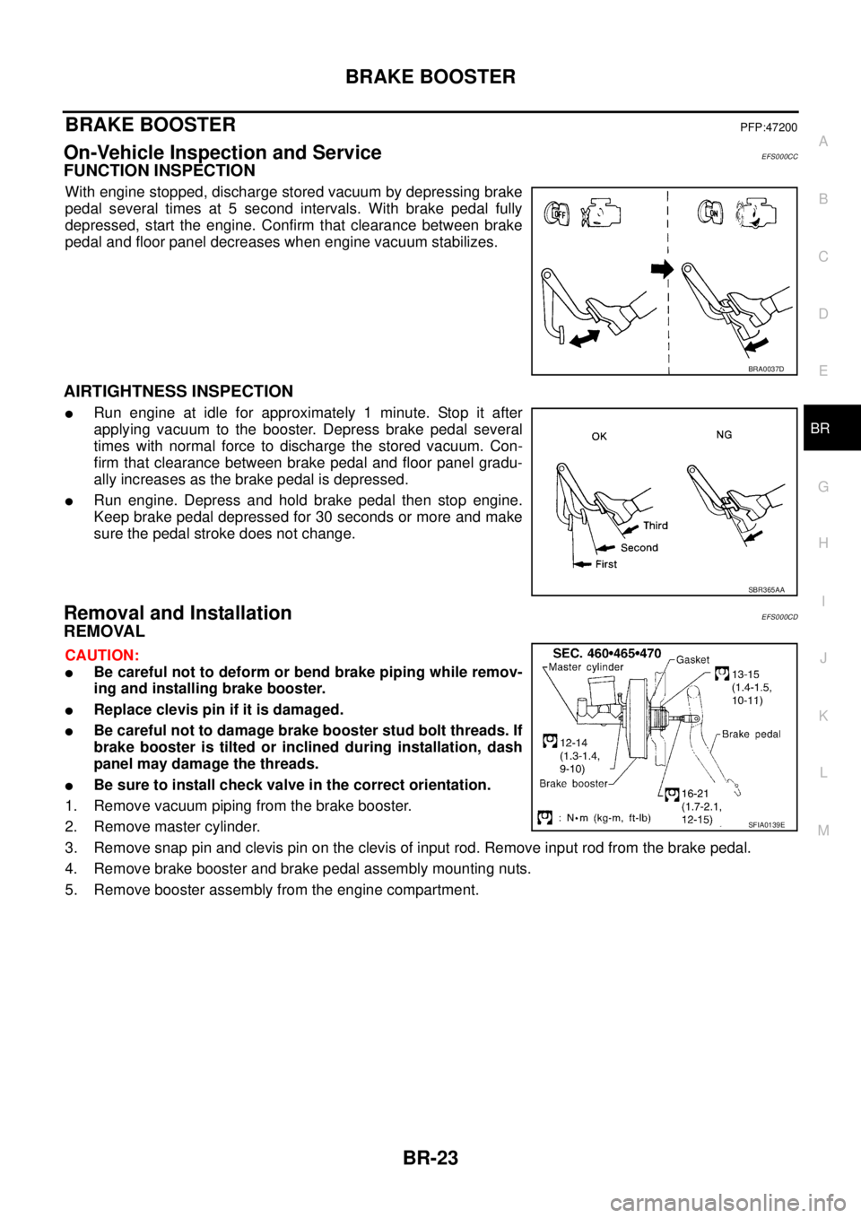
FUNCTION INSPECTION
With engine stopped, discharge stored vacuum by depressing brake
pedal several times at 5 second intervals. With brake pedal fully
depressed, start the engine. Confirm that clearance between brake
pedal and floor panel decreases when engine vacuum stabilizes.
AIRTIGHTNESS INSPECTION
�Run engine at idle for approximately 1 minute. Stop it after
applying vacuum to the booster. Depress brake pedal several
times with normal force to discharge the stored vacuum. Con-
firm that clearance between brake pedal and floor panel gradu-
ally increases as the brake pedal is depressed.
�Run engine. Depress and hold brake pedal then stop engine.
Keep brake pedal depressed for 30 seconds or more and make
sure the pedal stroke does not change.
Removal and InstallationEFS000CD
REMOVAL
CAUTION:
�Be careful not to deform or bend brake piping while remov-
ing and installing brake booster.
�Replace clevis pin if it is damaged.
�Be careful not to damage brake booster stud bolt threads. If
brake booster is tilted or inclined during installation, dash
panel may damage the threads.
�Be sure to install check valve in the correct orientation.
1. Remove vacuum piping from the brake booster.
2. Remove master cylinder.
3. Remove snap pin and clevis pin on the clevis of input rod. Remove input rod from the brake pedal.
4. Remove brake booster and brake pedal assembly mounting nuts.
5. Remove booster assembly from the engine compartment.
BRA0037D
SBR365AA
SFIA0139E